1
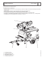
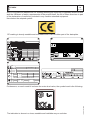
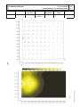
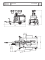
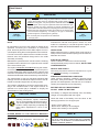
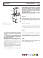
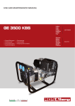
USE AND MAINTENANCE MANUAL
LIGHT & ENERGY
Codice
Code
Codigo
Kodezahl
8B9729003
TFII9Y J-4x1000
TFII9Y L-4x250
Edizione
Edition
Edición
Ausgabe
10.2013
M A D E
I N
I T A L Y
I
GB
F
GENERAL DESCRIPTION
M
0
TF II 9 Y J-4x1000
REV.0-10/13
The TF II-9Y J4x1000 a compact and functional model which integrates the functions of lighting tower and electric
power generator into a single machine.
The lighting tower is composed of:
• A hydraulic telescopic mast, which can be raised up to a maximum height of 9 meters and manually oriented within
a range of 340°
• A light assembly consisting of 4 IP65 floodlights with 1000 W metal halide lamps
• A silent generator driven by a water-cooled, low fuel consumption engine
• A command and control panel for the overall management and protection of the lighting tower
• 4 outriggers, 2 extendable and adjustable in height, to ensure the stability of the tower on any working surface
• The lighting tower can be equipped with a road trailer or a site tow.
1
2
1.
2.
3.
4.
5.
Floodlights assembly
Hydraulic telescopic mast
Road trailer or site tow
Command and control panel
Soundproof generator set
4
5
07/10/13 8B972-GB_10-13
3
INDEX
M 0
M 01
M 1.01
M 1.1
M 1.4
M 1.4.1
M 1.5
M 1.5.1
M 2
M 2.5 …
M 2.7
M 2.7.1
M3
M 4.2
M 20
M 23
M 23.1
M 21
M 31
M 39.12...
M 37 -…..
M 43 -…..
M 43.3 ...
M 45
M 46
M 60
M 61-…..
TF II 9 Y J-4x1000
M
1
REV.0-10/13
DESCRIPTION OF THE MACHINE
QUALITY SYSTEM
COPYRIGHT
NOTES
CE MARK
DECLARATION OF CONFORMITY
TECHNICAL DATA
ILLUMINATION DIAGRAM
SYMBOLS AND SAFETY PRECAUTIONS
SAFETY RULES
INSTALLATION
DIMENSIONS
UNPACKING
TRANSPORT AND HANDLING
SET-UP FOR OPERATION AND USE OF GENERATOR
PRELIMINARY CHECKS AND POSITIONING OF THE LIGHTING TOWER
FLOODLIGHTS ORIENTATION AND MAST RAISING/LOWERING
START AND STOP
CONTROLS
EP6 ENGINE PROTECTION
USING THE GENERATOR
MAINTENANCE OF THE MACHINE
MAINTENANCE OF THE LIGHTING TOWER
STORAGE
CUST OFF
ELECTRICAL SYSTEM LEGEND
ELECTRICAL SYSTEM
07/10/13 8B972-GB_10-13
I
GB
F
M
1.1
Notes
REV.0-10/13
INFORMATION
GENERAL INFORMATION
Dear Customer
We wish to thank you for having bought a high quality
product.
ANY USE OF THIS PRODUCT OTHER THAN THOSE
EXPLICITELY INDICATED IN THIS MANUAL RELIEVE
THE MANUFACTURER FROM ANY RESPONSIBILITY
ABOUT DAMAGES THAT MAY OCCUR TO PERSONS,
OR PROPERTY.
Our sections for Technical Service and Spare Parts will
work at best to help you if it were necessary.
To this purpose we advise you, for all control and overhaul operations, to turn to the nearest authorized Service
Centre, where you will obtain a prompt and specialized
intervention.
+ In case you do not profit on these Services and some
arts are replaced, please ask and be sure that are
used exclusively original parts; this to guarantee that
the performances and the initial safety prescribed by
the norms in force are re-established.
+ Notice: this manual does not engage the manufacturer, who keeps the faculty, apart the essential characteristics of the model here described and illustrated,
to bring betterments and modifications to parts and
accessories, without putting this manual uptodate
immediately.
+The use of non original spare parts will cancel
immediately any guarantee and Technical Service
obligation.
NOTES ABOUT THE MANUAL
Before actioning the machine please read this manual
attentively. Follow the instructions contained in it, in this
way you will avoid inconveniences due to negligence,
mistakes or incorrect maintenance. The manual is for
qualified personnel, who knows the rules: about safety
and health, installation and use of sets movable as well
as fixed.
You must remember that, in case you have difficulties
for use or installation or others, our Technical Service is
always at your disposal for explanations or interventions.
The manual for Use Maintenance and Spare Parts is an
integrant part of the product. It must be kept with care
during all the life of the product.
In case the machine and/or the set should be yielded to
another user, this manual must also given to him.
Do not damage it, do not take parts away, do not tear
pages and keep it in places protected from dampness
and heat.
18/10/13 M 1-1_TF GB
You must take into account that some figures contained in
it want only to identify the described parts and therefore
might not correspond to the machine in your possession.
M
1.4
CE MARK
REV.7-02/14
Any of our product is labelled with CE marking attesting its conformity to appliable directives and
also the fulfillment of safety requirements of the product itself; the list of these directives is part
of the declaration of conformity included in any machine standard equipment.
Here below the adopted symbol:
CE marking is clearly readable and unerasable and it can be either part of the data-plate.
TYPE
SERIAL N°
Made in UE-ITALY
TYPE/N°
VOLTAGE(V)
POWER(W)
Hz
G
P.F.
I.CL.
KVA
V(V)
I(A)
LTP POWER IN ACCORDANCE WITH ISO 8528
n
Pmax
RPM TEMP.
kW
ALTIT.
°C
m
IP
Kg
The indication is shown in a clear, readable and indeleble way on a sticker.
10/10/02 M1-4 GB
Furthermore, on each model it is shown the noise level value; the symbol used is the following:
I
GB
F
Dichiarazione conformità
Declaration of conformity
Déclaration de conformité
Konformitätserklärung
Declaración de conformidad
Declaração de conformidade
BCS S.p.A.
M
1.4.1
REV.2-10/13
Stabilimento di Cusago, 20090 (Mi) - Italia
V.le Europa 59
Tel.: +39 02 903521
Fax: +39 02 90390466
Sede legale:
Via Marradi 1
20123 Milano - Italia
DICHIARAZIONE DI CONFORMITA'
Déclaration de Conformité – Declaration of Conformity – Konformitätserklärung
Conformiteitsverklaring – Declaración de Conformidad
BCS S.p.A. dichiara sotto la propria responsabilità che la macchina:
BCS S.p.A. déclare, sous sa propre responsabilité, que la machine:
BCS S.p.A. declares, under its own responsibility, that the machine:
BCS S.p.A. erklärt, daß die Aggregate:
BCS S.p.A. verklaard, onder haar eigen verantwoordelijkheid, dat de machine:
BCS S.p.A. declara bajo su responsabilidad que la máquina:
GRUPPO ELETTROGENO DI SALDATURA / WELDING GENERATOR
GRUPPO ELETTROGENO / POWER GENERATOR
TORRE FARO / LIGHTING TOWER
Marchio / Brand :
Modello / Model :
Matricola / Serial number :
è conforme con quanto previsto dalle Direttive Comunitarie e relative modifiche:
est en conformité avec ce qui est prévu par les Directives Communautaires et relatives modifications:
conforms with the Community Directives and related modifications:
mit den Vorschriften der Gemeinschaft und deren Ergänzungen übereinstimmt:
in overeenkomst is met de inhoud van gemeenschapsrichtlijnemen gerelateerde modificaties:
comple con los requisítos de la Directiva Comunitaria y sus anexos:
2006/42/CE - 2006/95/CE - 2004/108/CE
Nome e indirizzo della persona autorizzata a costituire il fascicolo tecnico :
Nom et adresse de la personne autorisée à composer le Dossier Technique :
Person authorized to compile the technical file and address :
Name und Adresse der zur Ausfüllung der technischen Akten ermächtigten Person :
Persoon bevoegd om het technische document , en bedrijf gegevens in te vullen
Nombre y dirección de la persona autorizada a componer el expediente técnico :
ing. Benso Marelli - Consigliere Delegato / Managing Director ; V.le Europa 59, 20090 Cusago (MI) – Italy
_______________
Ing. Benso Marelli
Consigliere Delegato
Managing Director
MM 083.1
04/06/10 M1.4.1
Cusago,
I
GB
F
TF II 9 Y J-4x1000
TECHNICAL DATA
Technical data
LIGHTS AND MAST
GENERAL
CHARACTERISTICS
REV.0-10/13
Lamp type
Mast rotation
Mast
Wind load stability
Tank capacity
Running time
Ip protection
Acoustic power
Stabilizers
Dimensions (l x w x h)
(mm)
Weight (dry)
Tyres
ENGINE
GENERATOR
CONTROL PANEL
M
1.5
Model
Net power (st-by / prp)
Cylinders / displacement
Fuel consumption
Battery
Alternator
Output power
EP6 controller
Functions:
• Starter key
• Autostart
• Protections and alarms
TF II 9 Y J-4x1000
4 x 1000W - METAL HALIDE
340° - MANUAL
TELESCOPIC - 9 m - HYDRAULIC
UP TO 80 km/h
110 l
75 h (lights load only)
IP 44
LwA = 90 dBA
LpA = 65 dBA @ 7 m
4 (2 ADJUSTABLE)
Fully deployed (working conditions)
a) NO TRAILER 2210 x 1885 x 9000
b) SITE TOW 3150 x 1885 x 9000
c) ROAD TRAILER 3150 x 1885 x 9000
Transport conditions
d) NO TRAILER 1745 x 1325 x 2050
e) SITE TOW 3150 x 1325 x 2250
f) ROAD TRAILER 3135 x 1400 x 2250
a) NO TRAILER 940 kg
b) SITE TOW 1060 kg
c) ROAD TRAILER 1075 kg
• SITE TOW 2 x 185 / 65 R 14
• ROAD TRAILER 2 x 195 / 50 R 13
YANMAR 3TNV76
9 kW / 8.2 kW @ 1500 rpm
3 / 1116 cm3
1.5 l / h (lights only);
2.4 l / h (PRP)
12V 45 Ah
LINZ E1C13SC/4 - 8 kVA, SINGLE PHASE, SYNCHRONOUS, BRUSHLESS, 4 POLES PF =
0.9 ISOLATION CLASS = H
3.5 kVA 230 V / 15.2 A 50 Hz 1x16 A / 230 V 2P+T CEE
High temperature engine shut down; Low oil pressure shut down; Overspeed shut down; Battery
charge failure shut down; Delayed (5 min.) low fuel shut down; Overvoltage shut down; Battery
over / undervoltage alarm.
• Measurements
Hourmeter; r.p.m. meter; battery charge alternator voltage; battery voltage; generator voltage;
generator current; generator frequency.
Fuel level gauge - Emergency stop button - Siren - General protection circuit breaker - Output socket protection circuit breaker - Individual circuit breaker switches for the lamps - Mast up / down push buttons - External power supply
socket (230 V / 32 A 2P+T) and switch (optional).
PLEASE NOTE: the symbol
2000 / 14 / CE
07/10/13 8B972-GB_10-13
OUTPUT
Declared power according to ISO 8528-1 (temperature 25°C, 30% relative humidity, altitude 100 m above sea level).
(*Stand-by) = maximum available power for use at variable loads for a yearly number of hours limited at 500 h. No overload is admitted.
(**Prime power PRP) = maximum available power for use at variable loads for a yearly illimited number of hours. The average power to be taken during a
period of 24 h must not be over 80% of the PRP.
It’s admitted overload of 10% each hour every 12 h.
In an approximative way one reduces: of 1% every 100 m altitude and of 2.5% for every 5°C above 25°C.
ACOUSTIC POWER LEVEL
ATTENTION: The concrete risk due to the machine depends on the conditions in which it is used. Therefore, it is up to the end-user and under his direct
responsibility to make a correct evaluation of the same risk and to adopt specific precautions (for instance, adopting a I.P.D. -Individual Protection Device)
Acoustic Noise Level (LwA) - Measure Unit dB(A): it stands for acoustic noise released in a certain delay of time. This is not submitted to the distance of
measurement.
Acoustic Pressure (Lp) - Measure Unit dB(A): it measures the pressure originated by sound waves emission. Its value changes in proportion to the distance
of measurement.
The here below table shows examples of acoustic pressure (Lp) at different distances from a machine with Acoustic Noise Level (LwA) of 95 dB(A)
Lp a 1 meter = 95 dB(A) - 8 dB(A) = 87 dB(A)
Lp a 7 meters = 95 dB(A) - 25 dB(A) = 70 dB(A)
Lp a 4 meters = 95 dB(A) - 20 dB(A) = 75 dB(A)
Lp a 10 meters = 95 dB(A) - 28 dB(A) = 67 dB(A)
when with acoustic noise values, indicates that the device respects noise emission limits according to 2000/14/CE directive.
I
GB
F
TF II 9 Y J-4x1000
Lighting Tower 9m – 4 x 1000W metal halide
ILLUMINATION DIAGRAM
Power
Titano
1000 W
Flux
(each lamp)
85000 lm
Light type
Osram HQI-T
1000W/D
Color
temperature
7500 °K
Mounting
height
9m
REV.0-10/13
n° of lamps
4
07/10/13 8B972-GB_10-13
LUX
Fixture type
M
1.5.1
M
2
SYMBOLS AND SAFETY PRECAUTIONS
REV.0-10/13
SYMBOLS IN THIS MANUAL
- The symbols used in this manual are designed to call
your attention to important aspects of the operation of
the machine as well as potential hazards and dangers
for persons and things.
Moreover, this symbolism intends to draw your attention with the aim to give you indications for a correct
use and, as a result, to obtain a good operation of the
machine or equipment used.
SAFETY PRECAUTIONS
! DANGEROUS
This heading warns of an immediate danger for persons
as well for things. Not following the advice can result in
serious injury or death.
!
WARNING
This heading warns of situations which could result in
injury for persons or damage to things.
!
CAUTION
To this advice can appear a danger for persons as well
as for things, for which can appear situations bringing
material damage to things.
!
IMPORTANT
!
NOTE
!
ATTENTION
These headings refer to information which will assis you
in the correct use of the machine and/or accessories.
SYMBOLS
STOP - Read absolutely and be duly attentive.
Read and pay due attention.
DANGER
!
GENERIC DANGER - If the advice is not
respected damage can happen to persons or
things.
HIGH VOLTAGE - Attention High Voltage.
There can be parts in voltage, dangerous
to touch. The non observance of the advice
implies life danger.
FIRE - Danger of flame or fire. If the advice is
not respected fires can happen.
HEAT - Hot surfaces. If the advice is not
respected burns or damage to things can be
caused.
EXPLOSION - Explosive material or danger
of explosion. in general. If the advice is not
respected there can be explosions.
ACIDS - Danger of corrosion. If the advice is
not respected the acids can cause corrosions
with damage to persons or things.
PRESSION - Danger of burns caused by the
expulsion of hot liquids under pressure.
PROHIBITIONS
It is prohibited to smoke while filling the tank with fuel.
The cigarette can cause fire or explosion. If
the advice is not respected fires or explosions
can be caused.
It is prohibited to use water to quench fires on the electric
machines.
If the advice is not respected fires or damage
to persons can be caused.
Use only with non inserted voltage
It is prohibited to make interventions before
having disinserted the voltage.
ACCES FORBIDDEN to non authorized peaple
OBLIGATIONS
Use only with safety clothing
It is compulsory to use the personal protection means given in
equipment.
It is compulsory to use tools adapted to the
various maintenance works
If the advice is not respected damage can be
caused to things and even to persons.
24/10/13 M2GB_TF
I
GB
F
SAFETY RULES
GENERAL SAFETY INSTRUCTIONS
+ NOTE: the information contained in this manual
are subject to change without notice.
The instructions in this manual are intended as indicative only. It is the responsibility of the owner/operator to evaluate risks and potential damages in relation
to the use of the product in the specific conditions of
application. Remember that the non observance of
the indications of this manual may result in damage
to people or things.
In all cases, however, it is understood that the use
shall be in compliance with the applicable laws/regulations.
• Before operating the machine, read carefully the
safety instructions contained in this manual and
other manuals supplied (engine, alternator, etc.).
• All operations, handling, installation, use, maintenance, repair should be carried out by authorized
and qualified personnel.
• When operating, wear personal protective equipment (PPE): footwear, gloves, helmet, etc..
• The owner is responsible for maintaining the equipment in safe conditions.
Use only in perfect technical conditions
The machinery or equipment must be used in perfect technical condition. Remove immediately any
defects that may affect the safe conditions of use.
• Before starting to use this equipment it is important
to take knowledge of all the controls of the machine,
all its functions and its correct installation in order to
avoid accidents to people and damage to the machine itself. In particular, it is important to know how
to stop the equipment quickly in case of emergency.
• Do not allow the use of the machine to people unless previously instructed with all the information for
a proper, safe use.
• Forbid the access in the operational area to non authorized personnel, children and pets so as to protect them from possible injury caused by any part of
the machine.
SAFETY PRECAUTIONS DURING HANDLING
AND TRANSPORTATION
• Lift the machine using only the points allocated for
this function.
The lifting eye (or eyes) and the correct positioning
of the forks of the forklift are marked with specific
adhesives.
• Before moving a lighting tower lower the telescopic
mast and block properly all movable parts such as
the access doors, the mast, the outriggers, the floodlights.
M
2-5
REV.0-10/13
• Clear the operational area of possible obstacles
and all unnecessary personnel.
• Always use lifting equipment properly sized and
controlled by enabled bodies.
• It is forbidden to set on the frame of the equipment
objects or accessories that alter weight and center
of gravity and cause stresses not foreseen to the
lifting points.
• Do not submit the machine and the lifting equipment to swinging or shock which may transmit dynamic stress to the structure.
Equipments with trailers or site tows
• Never drag the machine without trailer (or site tow)
• Check for a correct assembly of the machine to the
towing device.
• Always make sure that the hook of the vehicle is
suitable for towing of the total mass of the trailer.
• Do not tow the trailer if the coupling devices are
worn or damaged.
• Check for proper tire pressure.
• Do not replace the tires with types different from the
original ones.
• Check that the brakes and the optical signaling of
the trailer are working properly.
• Verify that the bolts of the wheels are in place and
well tightened.
• Do not park the machine (on trailer or site tow) on a
steep slope.
For the stops, not followed by a work session, always engage the parking brake and / or block the
wheels by means of wheel chocks.
• Do not tow the trailer on bumpy roads.
• Do not exceed the maximum permissible speed on
public roads of 80 km/h with the trailer, in any case
comply with the legislation applicable in the country
of use.
• Do not use the site tow on public roads, this is intended for use only in private and delimited areas. The
maximum permitted speed is 40 km/h on smooth
surfaces (asphalt or concrete), adapt in each case
the speed to the type of ground.
SAFETY PRECAUTIONS DURING INSTALLATION
AND USE
• Always locate the lighting tower on a flat and solid ground, so as to avoid tipping, slipping or falling
during operation. Avoid using the lighting tower on
slopes greater than 10 degrees.
• Make sure the area immediately surrounding the
machine is clean and free from debris.
• Make sure the area above the lighting tower is free
from overhead cables or other obstacles. The lighting tower reaches a maximum height of 9 meters.
18/10/13 M2-5GB_TF
I
GB
F
SAFETY RULES
• Before raising the mast extract the outriggers located at the sides of the machine. Acting on the outriggers level the lighting tower making use of the
bubble, so as to bring the equipment in a horizontal
position. Make sure that the tower rests securely on
the outriggers. If the lighting tower is mounted on
road trailer pull the handbrake.
• Do not operate the lighting tower if the wind speed
exceeds the safe speed indicated or if it is expected
the arrival of storms or thunderstorms in the area.
• Lower the telescopic mast when the tower is not
used.
• Connect the machine to an earthing system according to the regulations in force at the place of installation. Use the ground terminal on the front of the
machine.
• Do not use the lighting tower with wet or damp hands and / or clothing.
• Use plugs suitable for the output sockets of the
machine and make sure that electrical cords are in
good condition.
• The machine must always be positioned so that
the exhaust gases are dispersed in the air without
being inhaled by people or living beings.
• If you use the machine indoors is necessary that
the installation is designed and built by skilled technicians in a workmanlike manner.
• During normal operation, keep doors closed. The
access to the internal parts should be allowed only
for maintenance reasons.
• Do not place objects or obstructions in the vicinity
of the air intakes and air outlets, a possible overheating of the generator could cause a fire.
• Keep area near to the muffler free from objects such
as rags, paper, cardboard. The high temperature of
the muffler could cause the burning of objects and
cause fire.
• Do not touch and do not place objects on the lamps
during operation or immediately after use. The lamps become very hot.
• Do not turn on the lamps without the protective
glass or with the same broken or damaged.
• Immediately stop the machine in case of malfunction.
Do not restart the machine without first having
found and fixed the problem.
SAFETY PRECAUTIONS DURING MAINTENANCE
• Make use of qualified personnel to carry out maintenance and troubleshooting.
• It is mandatory to stop the engine before performing
any maintenance on the machine.
• Always use protective devices and suitable equipment.
M
2-5.1
REV.0-10/13
• Always cut off power to the lamps and wait for their
cooling before performing any maintenance or replacement.
• Do not touch the engine, the exhaust pipes and the
muffler during operation or immediately after. Allow
the engine to cool before performing any operation.
• With the machine running pay attention to moving
parts such as fans, belts, pulleys.
• Do not remove the protections and the safety devices unless absolutely necessary, restore them after
completion of the maintenance or repair.
• Do not refuel while the engine is running or hot. Do
not smoke or use naked flames when refueling.
• Refuel only outdoors or in well ventilated areas.
• Avoid spilling fuel, especially on the engine. Clean
and dry any leaks before restarting the machine.
• Slowly unscrew the cap of the fuel tank and put it
back always after refueling.
• Do not fill the tank completely to allow for expansion
of the fuel inside.
• Do not remove the radiator cap when the engine is
running or still hot, the coolant may spurt out and
cause serious burns.
• Do not handle the battery without the use of protective gloves, the battery fluid contains sulfuric acid,
which is very corrosive and dangerous.
• Do not smoke, avoid any naked flames or sparks
near the battery, the vapors exhaled could cause
the battery to explode
18/10/13 M2-5GB_TF
I
GB
F
Installazione
Installation
Installation
Luftzirkulation
Instalación
TF II 9 Y J-4x1000
M
2.7
REV.0-10/13
M1.4
Made in
UE-ITALY
TYPE
SERIAL
N°
TYPE/N°
VOLTAGE(V)
POWER(W)
Hz
P.F.
G
I.CL.
n
KVA
V(V)
I(A)
IN ACCORDANCE
LTP POWER
TEMP.
RPM
ALTIT.
kW
WITH ISO
°C
m
8528
IP
Kg
M1.4
07/10/13 8B972-I_10-13
I
GB
F
Dimensioni
Dimensions
Dimensions
Abmessungen
Dimensiones
TF II 9 Y J-4x1000
M
2.7.1
2259
REV.0-10/13
1400
3136
360CoG
1188
I
GB
F
702CoG
750
1099
404
Abmessungen
Dimensiones
TF II 9 Y J-4x1000
M
2.7.2
REV.0-10/13
2259
Dimensioni
Dimensions
Dimensions
3163
1323
355CoG
1188
I
GB
F
702CoG
750
1099
404
Dimensioni
Dimensions
Dimensions
Abmessungen
Dimensiones
TF II 9 Y J-4x1000
M
2.7.3
REV.0-10/13
2054
I
GB
F
1780
1336
M
3
UNPACKING
REV.1-02/04
NOTE
!
+ Be sure that the lifting devices are: correctly mounted,
adequate for the weight of the machine with it’s packaging, and conforms to local rules and regulations.
When receiving the goods make sure that the product
has not suffered damage during the transport, that
there has not been rough handling or taking away of
parts contained inside the packing or in the set.
In case you find damages, rough handling or absence
of parts (envelopes, manuals, etc.), we advise you to
inform immediately our Technical Service.
For eliminating the packing materials, the User
must keep to the norms in force in his country.
1
A
B
1)Take the machine (C) out of the shipment packing. Take out of the envelope (A) the user’s manual (B).
2)Read: the user’s manual (B), the plates fixed on the
machine, the data plate.
C
30/03/00 M3GB
2
I
GB
F
M
4.2
Transport and handling
REV.0-10/13
General precaution when handling the machine.
ATTENTION
OK
OK
!
During handling of the lighting tower is essential
to pay close attention.
All handling operations must be performed by
qualified personnel.
For the characteristics of weight and size, an error
during the handling of the machine may result in
serious damage to the surrounding people and to
the machine itself.
In order to minimize the dangers involved in moving the
equipment it is important to follow carefully the requirements below:
• The transport must always be done with the engine
off, with electrical cables and starting battery disconnected, fuel tank empty.
• Clear the moving zone of all possible obstacles and
from all unnecessary personnel.
• Use properly sized lifting equipment regularly submitted to major overhaul by an authorized organisation.
It is prohibited to fasten objects or accessories
on the lighting tower baseframe that may modify
weight and center of gravity and may cause movements unforeseen by the lifting eyes.
• Do not subject the lighting tower and lifting equipment to abrupt or undulating movements that pass on
stress dynamics to the structure.
• Do not lift the equipment at heights greater than those
strictly necessary.
• To access the attachment points on the roof of the
machine, use approved ladders only. Climb the ladder being supported by a second operator and wear
special non-slip shoes.
NO
NO
NO
OK
NO
OK
NO
Moving the generating set via cables or chains
When lifting the genset with the aid of cables or chains it
is necessary to use equipment periodically checked by
a licensed organisation. Hook the cables only on to the
points provided for this use and shown via the appropriate stickers.
OK
Moving the generating set via forklift
When lifting with a forklift it is necessary to:
NO
14/10/13 M4.2-I_TF
• Insert the forks of the forklift into the specific pockets
located sideways and frontally on the baseframe, as
indicated in the figures.
• Fully insert the forks so that they stick out from the
opposite side and be careful to keep the equipment in
horizontal position.
Stickers on the base indicate where to place the lifter
forks.
I
GB
F
M
4.2.1
Transport and handling
REV.0-10/13
Moving by site trolley / trailer
!
CAUTION
the trailer can be driven only after you have done
the following:
• complete lowering of the mast
• engine shutdown
• positioning of the floodligths for the transportation (see picture)
Before starting to tow do the following:
•Fully raise the outriggers and lock the crank with its
clamp
•Fully retract the outriggers up to snap the locking pins
•Use the crank of the jockey wheel to raise / lower the
drawbar on the hook of the towing vehicle lock the
hook
•lock the hook
•Connect the cable from the trailer to the towing vehicle
and make sure all the lights work properly
•Make sure that the doors are locked
•Check for proper tire inflation of the trailer
Road trailer (CTV):
Site tow CTL:
this trailer is made by the manufacturer, it can not be
towed on public roads. Therefore it can only be used on
private roads and no through traffic zones.
The maximum speed allowed is 40 km/h on smooth surfaces (asphalt, cement) and, in any case, the laws in
force in the place of use should be respected.
Always follow the directions below for any tipe of tow:
• Do not park the machine (on trailer or site tow) on a
slant ground.
• When parking always use the emergency/hand brake
and/or safety clamps.
• DO NOT tow the trailer on bumpy roads.
Machine transportation by a motor vehicle
During the transportation with a motor vehicle it is
important to use appropriate belts/straps to stabilise the unit, thus avoiding that unexpected jumps
or jolts can cause damage to the baseframe and to
the engine or even worse the loss or the overturning of the load. It is the carriers responsibility to
always respect the Highway Code in force.
14/10/13 M4.2-I_TF
It is homologated for use on public roads. The maximum
speed allowed is 80 km/h, in any case, the transportation laws in force in the place of use shall be respected.
Set-up for operation
Water cooled systems
M
20
REV.0-10/13
BATTERY WITHOUT MAINTENANCE
Connect the cable + (positive)
to the pole + (positive) of the
battery (after having taken
away the protection), by
properly tightening the clamp.
Check the state of the battery
from the colour of the warning light which is in the
upper part.
- Green colour: battery OK
- Black colour: battery to be recharged
- White colour: battery to be replaced
DO NOT OPEN THE BATTERY.
LUBRICANT
OIL REPLACEMENT
To replace the engine oil, refer to the instruction
manual of the engine about the viscosity and the
type recommended.
Originally, the machine is supplied with engine oil
type:
ENI SIGMA PERFORMANCE 15W-40SE
REFUELLING AND CONTROL:
Carry out refuelling and controls with motor at level
position.
1. Remove the oil-fill tap (24)
2. Pour oil and replace the tap
3. Check the oil level using the dipstick (23); the oil
level must be comprised between the minimum
and maximum indicators.
!
AIR FILTER
Check that the dry air filter is correctly installed and that there are no leaks around the
filter which could lead to infiltrations of non-filtered
air to the inside of the motor.
FUEL
!
ATTENTION
Do not smoke or use open flames during
refuelling operations, in order to avoid
explosions or fire hazards.
Fuel fumes are highly toxic; carry out
operations outdoors only, or in a wellventilated environment.
Avoid accidentally spilling fuel. Clean
any eventual leaks before starting up
motor.
Refill the tank with good quality diesel fuel, such as
automobile type diesel fuel, for example.
For further details on the type of diesel fuel to use,
see the motor operating manual supplied.
Do not fill the tank completely; leave a space of
approx. 10 mm between the fuel level and the wall
of the tank to allow for expansion.
In rigid environmental temperature conditions, use
special winterized diesel fuels or specific additives
in order to avoid the formation of paraffin.
ATTENTION
It is dangerous to fill the motor with too much oil,
as its combustion can provoke a sudden increase
in rotation speed.
18/10/13 M20-R-HO2_TF-GB
I
GB
F
I
GB
F
Set-up for operation
Water cooled systems
M
20.1
REV.0-10/13
COOLING LIQUID
!
ATTENTION
Do not remove the radiator tap with the
motor in operation or still hot, as the
liquid coolant may spurt out and cause
serious burns. Remove the tap very
carefully.
Remove the tap and pour the liquid coolant into the
radiator; the quantity and composition of the liquid
coolant are indicated in the motor operating manual.
Replace the tap, ensuring it is perfectly closed.
After refilling operations, allow the motor to run for
a brief time and check the level, as it may have diminished due to air bubbles present in the cooling
circuit; restore the level with water.
To replace the liquid coolant, follow the operations
described in the motor operating manual.
GROUNDING CONNECTION
The grounding connection to an earthed installation is obligatory for all models equipped with a
differential switch (circuit breaker). In these groups
the generator star point is generally connected to
the machine’s earthing; by employing the TN or TT
distribution system, the differential switch guarantees
protection against indirect contacts.
In the case of powering complex installations requiring or employing additional electrical protection
devices, the coordination between the protection
devices must be verified.
For the grounding connection, use the terminal (12);
comply to local and/or current regulations in force
for electrical installations and safety.
ATTENTION:
The engine cooling system is originally filled with
coolant type:
AGIP ANTIFREEZE EXTRA
18/10/13 M20-R-HO2_TF-GB
During the engine life it is strongly recommended
to use the same coolant type. This is because a
coolant change would require a careful cleaning of
the cooling system, which is not an easy job. A lack
in tacking these precautions would result in the mix
of different additives used in different coolants which
would originate gelatinous substances capable of
obstructing the cooling system.
I
GB
F
Preliminary checks and positioning
Start-up
M
23
REV.0-10/13
!
ATTENTION
Before operating the lighting tower make sure
that all safety regulations concerning installation
and use are satisfied, as indicated in the relevant
section of this manual!
PRELIMINARY CHECKS
• Check the engine oil level, hydraulic oil and radiator fluid
• Check the fuel level
POSITIONING OF THE OUTRIGGERS AND LEVELLING OF THE TOWER
In particular, be sure that:
• the surface on which the lighting tower is placed
is flat and free of obstacles
• the wind speed does not exceed 80 km/h
• there are no obstacles or overhead power lines
above the lighting tower
• the status of the lighting tower is adequate, in
general
• the lifting ropes of the mast are in perfect condition.
• Block the wheels using the hand brake (road trailer) or chocks (site-tow)
• Raise the locking pins of the extension arms of
the front outriggers and extract them until the pins
block again the arms in their extended position.
• Lower the rear outriggers and secure them with
the locking lever
• Lower the front outriggers and adjust the lighting
tower position by acting on their handles, looking
at the bubble level on the machine, until the horizontal position is reached.
• Lower the jack of the drawbar (site-tow) or the
jockey wheel (road trailer) until it is resting on the
ground.
B
D
A Wheel chocks
B. Outriggers extension arm
C. Front outrigger
D. Rear outrigger
E. Jack
C
A
18/10/13 M23_TF-GB
E
I
GB
F
M
23.1
Floodlights orientation and mast raising/lowering
Start-up
REV.0-10/13
ORIENTATION OF FLOODLIGHTS AND MAST
RAISING AND LOWERING OF THE MAST
!
ATTENTION
Before starting the engine, make sure that switches
of the lamps on the panel are all in OFF position.
1
3
2
Start the generator with the key on the front panel,
following the instructions in the section "START AND
STOP (EP6)".
Put the circuit breaker (A) in ON position.
Activate the raise of the mast through the relevant
button on the control panel (B) until the mast is fully
extended.
Turn on the lamps by means of the circuit breakers
(D) on the front panel.
After use, turn off the lamps before actuating the
lowering of the mast.
Lower the mast by pressing the appropriate button
(C) on the control panel.
The floodlights beam can be oriented, according to
the needs, by acting in the following two ways:
B
• by adjusting the inclination of each floodlight
• by rotating the mast in the desired direction.
To adjust the angle of the floodlights loosen the
clamping lever (1), turn the floodlight to the desired
position and lock again.
A
D
EMERGENCY LOWERING OF THE MAST
In case of emergency due to engine failure, or due
to failure of the hydraulic or the electrical system,
use the bypass tap of the solenoid valve to lower
the mast. When the mast is completely down, close
the tap again.
!
ATTENTION
After switch off, the metal halide lamps require a
cooling time of about 15 minutes before subsequent switch on.
18/10/13 M23_TF-GB
To rotate the mast lift the pin (2) and turn it in such
a way as to keep it extracted. Direct the mast in the
desired direction by acting on the handles (3). Unlock the pin (2) and slightly rotate the mast until the
pin gets into a hole, thereby locking of the rotation
of the mast.
C
I
GB
F
M
21
START AND STOP (EP6)
REV.0-10/13
Check daily
!
NOTE
Do not alter the primary conditions of regulation
and do not touch the sealed parts.
The starting of the lighting tower can be effected in 2
different modes:
2) Remote starting with TCM35
Put the “Local/Remote” selector on Local. Connect TCM35 to the plug on the front panel and put
the switch on “0”.
Turn the key on ON in the EP6, wait for the various
signals to go out then press the button “AUTO” in
the EP6 until the led “AUTO” flashes.
Shift the switch on “I” in the TCM35 and automatically the starting cycle will start. On the machines
with mounted glow plugs appears in the display
EP6 (for about 5 secs), the symbol “UUUU“; the
starting cycle includes 3 starting trials.
When the engine starts the led “AUTO” remains lit
continuously and simultaneously the red warning
light will light in the TCM35. Stop:
it is COMPULSORY to disconnect the load first,
then shift the switch of the TCM35 on “0”, the
engine will stop immediately.
!
CAUTION
MACHINE WITH EMERGENCY BUTTON
Pressing the button the engine will stop immediately in any working condition.
Turn clockwise to reset the button.
!
CAUTION
!
NOTE
RUNNING-IN
During the first 50 hours of operation, do not use
more than 60% of the maximum output power of
the unit and check the oil level frequently, in any
case please stick to the rules given in the engine
use manual.
For safety reason the key must be kept by qualified
personel.
02/02/06 M21_EP6-GB_TF
1) Start with EP6 key (Engine Control)
Put the “Local/Remote” selector on Local. Turn the
key on “ON”, the EP6 display shows, only on the
machines with mounted glow plugs for 5 secs, the
symbol “UUUU”, then the message “Sta” appears
the engine can be started, for then turn the key
on “start” and start the engine.
On the display the word “Sta” remains for about
20 sec then automatically disappears; the engine
must be started within 20 secs, otherwise the EP6
blocks the starting and on the display the word
“fail” appears. Turning the key on “OFF” the EP6
is reset and a new starting cycle can be fixed.
Stop:
it is COMPULSORY to disconnect the load first,
then to stop the engine turn the key on “OFF”.
Comandi
Controls
Commandes
Bedienelemente
Mandos
TF II 9 Y J-4x1000
REV.0-10/13
5
6
7
8
1
2
4
3
9
10
11
12
POS.
1
2
3
4
5
6
7
8
9
10
11
12
13
M
31
DESCRIZIONE
Interruttore magnetotermico generale
Pulsante salita palo
Pulsante discesa palo
Interruttori magnetotermici lampade
Protezione motore EP6
Selettore start local / remote
Indicatore livello carburante
Interruttore differenziale
Presa comando a distanza
Avvisatore acustico
Pulsante stop emergenza
Presa di corrente
Presa di messa a terra
13
DESCRIPTION
General circuit breaker
Mast-up button
Mast-down button
Circuit breakers of the lamps
Engine protection EP6
Local / remote start selector
Fuel gauge
Ground fault circuit interrupter
Remote control socket
Siren
Emergency stop button
Auxiliary power socket
Earth terminal
07/10/13 8B972-I_10-13
I
GB
F
PROTECTIONS
M
39.12
EP6 ENGINE PROTECTION
REV.1-03/11
4 digits DISPLAY
[UP DOWN]
Button
Ideograms
Green LED
engine on
Button
[AUTO]
Button
[F1]
AUTO (Yellow
Led)
Button
[ENTER] (*)
Button [+]
Key
(*)
(OFF-ON-START)
Button [-] (*)
(*) The use of these buttons is
reserved only to the manufacturer
of the generating set.
1.0 INTRODUCTION
The EP6 features Engine and Generating Set control
and monitoring. The EP6 provides visual indication
by means of LEDs (solid state lamps) and a Display
(see section 10.0). It features OFF, MAN and AUTO
operating modes. The display gives Messages for
alarms and Measurement indications.
EP6 has programmable parameters. Please contact the producer of the generating set to receive
instructions related to programming.
2.0 OPERATING MODE selection
The EP6 features AUTO (section 2.1), MANUAL
(section 2.2) and OFF (section 2.3) operating modes.
When the power supply is switched on, the EP6
behaves as follow:
A) if the KEY-SWITCH is in the OFF position, the
EP6 enters the OFF operating mode.
B) if the KEY-SWITCH is in the ON position, the EP6
enters the AUTO operating mode. That is, if the
EP6 was in AUTO prior to the supply removal. If
not, the EP6 enters the MANUAL operating mode.
2.1 AUTO operating mode
To enter the "AUTO" operating mode use the following instructions:
A) - Turn ON the key switch: the Display and LEDs
illuminate for 1 second.
B) - Wait for the end of the LAMP test, then push the
AUTO pushbutton after the [UUUU] (Pre-glow)
or [Sta-] (Start prompt) has been displayed. After this, the yellow Led AUTO will illuminate. If
the REMOTE START input is not operative, the
LED will flash. If operative, the LED illuminates
continuously and a start cycle will take place
(NOTE: the EP6 shuts down the display during
the crank).
C) - In order to cancel the AUTO operating mode,
push the AUTO pushbutton (the yellow Led will
turn OFF) or turn the KEY-SWITCH to OFF.
Once in AUTO, the EP6 waits for a REMOTE
START activation (see section 7.0).
In case of an Automatic Periodic Test (A.P.T.),
the display will show the message [tESt].
2.2 MANUAL operating mode
To start the engine follow the instructions:
A)-Turn ON the KEY-SWITCH; the EP6 illuminates
the LEDs and Display.
B)-If the display shows the message [uuuu], the EP6
is counting the PRE-GLOW time; wait until the
message disappears.
C)-After the display shows the flashing message
[StA-] (NOTE), turn the Key to START position
(momentary position with spring-loaded return)
until the engine starts. The message [ . . . .] indicates a MANUAL start.
D)-To stop the engine, turn the KEY SWITCH to
OFF.
NOTE: EP6 shows the blinking [StA-] message
for 20 seconds. After this time, if the engine does
not start, the EP6 displays the message [FAIL]
(Fail to start, see section 4.07).To clear the alarm,
turn the KEY-SWITCH to OFF.
2.3 OFF operating mode
This function is obtained by turning the KEY SWITCH
to OFF. The OFF operating mode clears the fault
alarms and shuts down the Display after 5 seconds.
A blinking dot indicates the presence of the power
supply. Press one of the pushbuttons to energize
the display. In OFF operating mode, the EP6 allows
reading of the parameters (see section 6.0).
3.0 DISPLAY features
The EP6 features a 4 Digit Display (section10.0) to
show measurements, settings and error messages.
The [UP-DOWN] pushbutton selects one of the following menus:
[AXXX] (*) Generator Current measurement
[UXXX] The Voltage of the Generating Set
[rPM] [XXXX] Speed of the engine
[HXX.X] Frequency of the Generator
[bXX.X] Battery Voltage
[cXX.X] Charger Alternator Voltage
[ h ] [XXXX] HOUR METER (the message [h] appears for a moment, and then, the counter will be
displayed continuously).
(*): the symbol "X" means a numerical field.
12/10/05 M39GB
FRONT PANEL
PROTECTIONS
EP6 ENGINE PROTECTION
M
39.12.1
REV.1-03/11
[OIL]
[ °C ]
[O.SPd.]
[U.SPd]
[bELt]
[ALAr]
[FUEL](1)
[FAIL]
[E 04]
[E 05](2)
[Hi H](2)
[Lo H](2)
[Hi U] (2)
[Lo U](2)
[XX.X]
[Err ]
Low Oil Pressure
High Temperature
Over Speed of the engine
Under Speed of the engine
Failure of the belt
External Emergency Stop
Low Fuel in the tank
Starting Failure Alarm
Alternator Failure
Generator Overload
Generator Over Frequency
Generator Under Frequency
Generator Under Voltage
Generator Under Voltage
Battery Voltage
Memory error
(1) [FUEL] This message indicates Low Fuel in the
tank . The engine stops if the contacts remain closed
for 5 minutes continuously.
(2) To determine the value that caused the failure,
push the [F1] pushbutton.
4.1 OPERATING messages
EP6 features messages to inform you about the
following:
[uuuu]Glow-plugs timing
[U— ] Voltage out of range
[StA-] Start prompt
[. . . .] Starting by key switch
[rESt] Rest timing
[tESt] Automatic Test
[CAL] Calibration
[ProG]Programming
[StOP]Stopping cycle
5.0 LEDs for visual indication
The EP6 features two LEDs (see section 10.0) to
indicate the following conditions:
[ENGINE RUNNING]: this green led illuminates
when the engine is running.
[AUTO]: this yellow LED blinks to indicate a standby
mode. The EP6 monitors the REMOTE CONTROL
and expects a command. The LED illuminates continuously when the REMOTE START is activated.
5.1 LEDs and Display Test
A test of the LEDs and DISPLAY is obtained automatically anytime the key switch is turned ON. The
LEDs and DISPLAY light up for about 1 second.
6.0 Parameters and settings
The unit is programmed by the supplier of the Generating Set. Contact the Generator manufacturer in
order to have the permission to program the module. It is possible to read the status of the internal
programming at anytime. Follow the instructions:
A) - Turn the Key in OFF (if the display indicates
[STOP], wait until it disappears)
B) - Push the pushbutton [F1] the display will show
the first programmable parameter [P.0].
C) - Push the pushbutton [F1] the display will indicate the value of the parameter ([ 1"]).
D) - Push the pushbutton [UP-DOWN] to select a
parameter. Push [F1] to display the setting.
E) - The display returns to menu mode if you have
not used the pushbuttons for 2 minutes.
The list of the parameters follows ([ ' ] means
minutes and [ '' ] means seconds). Some parameters may differ according to the programming
done by the genset manufacturer.
12/10/05 M39GB
4.0 ALARM messages
The alarms are displayed by means of messages.
In case of alarm consult your Generating Set manufacturer. To remove the message, turn OFF the KEYSWITCH. The EP6 may show one of the following:
PROTECTIONS
EP6 ENGINE PROTECTION
M
39.12.2
REV.0-10/05
Parameter [Default]
[P.0]
Remote Start Delay Timing (Input #7) [ 1"]
Range: 1-59 secs or 1-15 mins
Seconds or minutes of continuous REMOTE START command to initiate the automatic engine start (see section 7.0 and [P20] in this section).
Remote Stop Delay Timing (Input #7) [ 1"]
Range: 1-59 secs or 1-15 mins
Seconds or minutes of continuous absence of the REMOTE START command to
initiate the stop cycle (see section 7.0 and [P.20] in this section).
Crank Timing (Output #10) [ 5"]
Range:1-20 seconds Maximum insertion time of the Starter Motor.
Engine Running Trigger (Input #1) [ 8.0]
Range: 3V-24V, [inh]. If the voltage of the Charger Alternator rises above the [setting], the Starter Motor is disconnected.
Rest Timing [ 3"]
Range: 3-20 secs. Time interval between starting attempts
Starting Attempts [ 3 ]
Range: 1-10 This parameter sets the number of attempts in the automatic start cycle
Generator UnderVoltage, short-circuit [ inh.]
Range: 80-400V. If the voltage drops under the [setting] for at least 6 secs, or under
[setting]-20% for 1 sec, the Under-Voltage protection [Lo U] will shut down the engine.
Generator Over-Voltage [500V]
Range: 110-550V or [inh.]. If the Generator voltage rises above the [setting] for at
least 2 seconds, the EP6 will energize the over voltage protection [Hi U] (see section
4.0) to stop the engine. The [inh.] code inhibits the over voltage.
Generator Under-Frequency [Inh.]
[inh.] 1 to 99Hz ([inh]=disables the under frequency)
This protection is delayed by about 6 seconds. The EP6 shuts down the engine and
the display will show the [Lo H] message.
Generator Over-Frequency [55]
45 Hz to [inh.] ([inh.] disables the over frequency)
This protection is delayed by about 2 seconds. The EP6 shuts down the engine and
displays [Hi H]
Current Transformer Size [...]
The range is 10/5 up to 1000/5
Generator Overload Setting [inh.]
Range: [inh.] to 1000 AThe EP6 shuts down the engine after a delay of 6 secs and
shows the message [E05].
Generator Failure Alarm [OFF]
selection: [on] or [OFF].The code [on] enables the Generator failure alarm. The EP6
shows the [E04] message and the engine will shut down.
Glow Plugs/Choke Control (Output #11) [ 5"]
Range: 1 to 99 secs.The EP6 energizes the output #11 for the programmed time.
Output Control [ 0 ]
The following options are available:
[ 0] None - [ 1] Choke Control - [ 2] Glow Plugs Control - [ 3] Choke Control
Belt Break Control [ON]
Selection: [on] or [OFF]. The Belt Break alarm is indicated by means of the message
[bELt]
Stop Solenoid Timing [ 2"]
Range: 2-99 secs. Duration of the Stop cycle.
[P.1]
[P.2]
[P.3]
[P.4]
[P. 5]
[P.6]
[P.7]
[P.8]
[P.9]
[P.10]
[P.11]
[P.12]
[P.13]
[P.14] [P.15]
[P.16]
12/10/05 M39GB
Display
PROTECTIONS
EP6 ENGINE PROTECTION
M
39.12.3
REV.1-03/11
[P.18]
[P.19]
[P.20]
[P.21]
[P.22]
[P.23]
[P.24]
[P.25]
[P.26] [P.27] [P.28] [P.29] [P.30] [P.31] Alarm Output Timing [ 1']
[inh.] 1-59 secs 1-15 mins and [cont]. Time-out of the alarm output. The code [cont]
disables the time-out, and the alarm remains energized until the OFF operating mode
is selected. The [inh.] mode enables the use of the external contactor
Temperature Switch [n.o.]
Selection: [n.o.] or [n.c.]
[n.o.] the engine shuts down if the contact closes
[n.c.] the engine shuts down if the contact opens
ALARM Control [n.c.]
Selection: [n.o.] or [n.c.]
[n.o.] the engine shuts down if the contact closes
[n.c.] the engine shuts down if the contact opens
Remote Start [n.o.]
Selection: [n.o.] or [n.c.]
[n.o.] the engine starts if the contact closes
[n.c.] the engine starts if the contact opens
Under Speed setting [1200]
[Inh.] or 100-4000 r.p.m. The [Inh.] code disables the Under Speed shut down.
Over Speed setting [1700]
100-4000 rpm or [Inh.]. The EP6 provides one second bypass delay. The [Inh.] code
(>4000 r.p.m.) disables the Over Speed shut down.
Number of Teeth of the Flywheel [Inh.]
[Inh.] or 1-500 teeth.
The [Inh.] code disables the reading of the Speed (section 3.0), the Over/Under
Speed alarms, and the Crank termination (see [P.24]).
Crank OFF [Inh.]
Crank Termination setting: 100-800 rpm
If the speed rises above the setting, the EP6 terminates the crank cycle. One seconddelay avoids false termination.The code [Inh.] inhibits the crank termination
Low Oil Pressure Alarm By-Pass [ 6"]
Range: 0-99 secs. By-Pass Delay to ignore the Oil Pressure (input #3) during the
engine starting cycle. This input requires normally closed contact
Automatic Periodic Test Cycle [inh.]
Range: [inh.], 1-99 days
This is the interval time between the automatic periodic tests of the engine. The code
[inh.] disables the Automatic Periodic Test (see section 19.0)
Automatic Engine Test Duration [ 10']
Range: 1-99 minutes.
This is the duration of the automatic engine test.
Generator warm-up timing [ 20"]
Range [inh.] 1-59 secs or 1-15 mins ([inh.]=No warm-up)
Active only when [P17]= [inh.] and the ALARM output is used to drive the contactor
Generator cooling timing [ 30"]
Range [inh.] 1-59 secs or 1-15 mins ([inh.]=No cooling)
Active only when [P28]= [inh.] and the ALARM output is used to drive the GEN-SET
contactor
N° poles of the alternator [...]
Range [inh.] - [2] = 2 pole alternator - [4] = 4 pole alternator
Engine shut-down delay for low fuel [5']
Range [inh.] = provides only optical - acoustical warning - 1 - 99 min.
12/10/05 M39GB
[P.17] PROTECTIONS
EP6 ENGINE PROTECTION
M
39.12.4
REV.1-03/11
7.0 REMOTE START
The EP6 features REMOTE START only in AUTO
operating mode.
To operate the REMOTE START, follow the instructions.
The EP6 will start the engine after the programmed
number of days and the engine will run for the programmed time. To determine how the Automatic
Periodic Test is programmed enter the Reading
Mode (section 6.0 parameter [P.26] and [P.27]).
A) - Turn the KEY-SWITCH to the ON position; the
Display and LEDs illuminate for 1 sec.
B) - Wait until the end of the LEDs test.
C) - Push the AUTO pushbutton as soon as possible
(otherwise, after 20 seconds the EP6 enters the
STARTING FAILURE); the [AUTO] yellow LED
will illuminate as described in the section 4.
IMPORTANT NOTES
If the supply (battery voltage) is removed, the
EP6 loses the counts and timings. If the supply restores, the EP6 starts to count the A.P.T.
according to the programmed parameters [P.26]
and [P.27]. It is important to synchronize the
power on sequence with the desired Automatic
Periodic Test.
REMOTE START SWITCH:
If the REMOTE START input is activated, the
[AUTO] yellow LED illuminates continuously and the
display will indicate the count down of the internal
start delay timer. The engine will start after the programmed start delay time. If the REMOTE START
is deactivated, the EP6 drives the stop delay time.
The display will indicate the count down and the
[AUTO] yellow LED will flash. The engine will stop
after the programmed stop delay time.
8.0 SAFETY
!
NOTE
High voltage is present inside the EP6. To avoid
electric-shock hazard, operating personnel must
not remove the protective cover. Do not disconnect the grounding connection. Any interruption of
the grounding connection can create an electric
shock hazard. Before making external connections, always ground the PANEL first by connecting the control panel to ground.
The EP6 does not use a clock to count the programmed days ([P.26] setting, section 6.0). The
maximum error and drift of the counter is +/-0,5%.
The user may experiment with shifting the periodic
tests. To avoid error accumulation, and in case your
unit is programmed to allow Automatic Periodic Test,
we recommend the following procedures.
- disconnect the power supply of the EP6 (consult
your genset supplier)
- wait for the desired start time (external clock reference)
- apply the power supply to the EP6 (consult your
genset supplier)
- select the "AUTO" operating mode
12/10/05 M39GB
9.0 Automatic periodic TEST
M
43
MAINTENANCE
REV.1-01/13
!
MOVING
PARTS
can injure
WARNING
●● Have qualified personnel do maintenance and troubleshooting work.
●● Stop the engine before doing any work inside the machine. If for any
reason the machine must be operated while working inside, pay attention moving parts, hot parts (exhaust manifold and muffler, etc.)
electrical parts which may be unprotected when the machine is open.
●● Remove guards only when necessary to perform maintenance, and
replace them when the maintenance requiring their removal is complete.
●● Please wear the appropriate clothing and make use of the PPE (Personal Protective Equipment), according to the type of intervention
(protective gloves, insulated gloves, glasses).
●● Do not modify the components if not authorized.
- See pag. M1.1 -
NOTE
By maintenance at care of the utilizer we intend all the
operatios concerning the verification of mechanical
parts, electrical parts and of the fluids subject to use or
consumption during the normal operation of the machine.
For what concerns the fluids we must consider as maintenance even the periodical change and or the refills
eventually necessary.
Maintenance operations also include machine cleaning
operations when carried out on a periodic basis outside
of the normal work cycle.
The repairs cannot be considered among the maintenance activities, i.e. the replacement of parts subject to
occasional damages and the replacement of electric and
mechanic components consumed in normal use, by the
Assistance Authorized Center as well as by manufacturer.
The replacement of tires (for machines equipped with
trolleys) must be considered as repair since it is not delivered as standard equipment any lifting system.
The periodic maintenance should be performed according to the schedule shown in the engine manual. An
optional hour counter (M) is available to simplify the
determination of the working hours.
!
IMPORTANT
In the maintenance operations avoid that
polluting substances, liquids, exhausted
oils, etc. bring damage to people or things or
can cause negative effects to surroindings,
health or safety respecting completely the
laws and/or dispositions in force in the
place.
ENGINE and ALTERNATOR
PLEASE REFER TO THE SPECIFIC MANUALS
PROVIDED.
Every engine and alternator manufacturer has
HOT surface
can
hurt you
maintenance intervals and specific checks for each
model: it is necessary to consult the specific engine or
alternator USER AND MAINTENANCE manual.
VENTILATION
Make certain there are no obstructions (rags, leaves or
other) in the air inlet and outlet openings on the machine,
alternator and motor.
ELECTRICAL PANELS
Check condition of cables and connections daily.
Clean periodically using a vacuum cleaner, DO NOT USE
COMPRESSED AIR.
DECALS AND LABELS
All warning and decals should be checked once a year
and replaced if missing or unreadable.
STRENUOUS OPERATING CONDITIONS
Under extreme operating conditions (frequent stops
and starts, dusty environment, cold weather,extended
periods of no load operation, fuel with over 0.5% sulphur
content) do maintenance more frequently.
BATTERY WITHOUT MAINTENANCE
DO NOT OPEN THE BATTERY
The battery is charged automatically from the battery
charger circuit suppplied with the engine.
Check the state of the battery from the colour of the
warning light which is in the upper part.
- Green colour: battery OK
- Black colour: battery to be recharged
- White colour: battery to be replaced
!
NOTE
THE ENGINE PROTECTION NOT WORK WHEN THE
OIL IS OF LOW QUALITY BECAUSE NOT CHARGED
REGULARLY AT INTERVALS AS PRESCRIBED IN THE
OWNER’S ENGINE MANUAL.
05/09/05 M43GB
I
GB
F
I
GB
F
HYDRAULIC POWER PACK
MAINTENANCE
M
43.3
REV.0-10/13
WIRE ROPES
A
B
Periodically check that the steel ropes of the mast
are in perfect conditions. If there is evidence of
wear, abrasion, broken wires or loose connection
do not use the lighting tower and plan immediately
the cables replacement .
CAUTION: When replacing use ropes of the same
type of the originals. For this purpose, it is highly
advisable to use original spare parts.
PULLEYS
C
A. Electric Motor
B. Bypass tap for manual lowering of the mast
C. Hydraulic fluid tank
Periodically check the regular rotation of the pulleys and the correct position of the ropes on the
pulleys. Periodically lubricate with lithium multifunctional grease.
TELESCOPIC MAST
Check the regular movement of the mast during
the raise and the lowering. Periodically grease the
mast with anti-corrosion waterproof spray lubricant.
LAMPS
In case of need of replacement, do not directly
touch the lamps with your fingers, use a cloth or
use cotton gloves. Pay attention to the high temperature that the lamps reach during operation: if
possible, wait them to cool down before replacing.
TIRES
On the trailer/site-tow versions periodically verify
the proper tire pressure (2.2 bar).
05/09/05 M43I
• Check the level and condition of the hydraulic fluid. Carry out the check with the mast down and
cool fluid.
•It is recommended a first fluid change after the
first 10 hours. Do the following oil changes within
3000 hours or once a year.
• The hydraulic power pack is supplied from factory with hydraulic oil type: AGIP OSO 46
• When topping up, it is important not to mix
hydraulic fluids of different manufacturers, or different types, which may cause the formation of
sludge and sediments that could affect the proper
operation of the power pack.
• Each time you change the hydraulic fluid, replace
(or wash and clean) the inlet filter and do an internal cleaning of the tank.
• For the oil replacement, use oils with a high viscosity index and temperature range appropriate
to the conditions of use.
WWW.MOSA.IT
MOSA div. della BCS S.p.A.
Stabilimento di Viale Europa, 59
20090 Cusago (MI) Italia
Tel. + 39 - 0290352.1
Fax + 39 - 0290390466