1
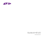
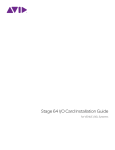
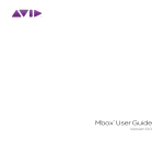
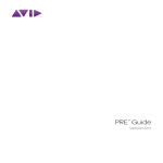
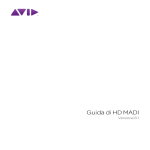
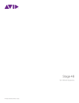
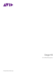
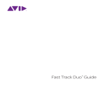
Mix Rack for VENUE Systems PN 9321-62801-00 REV C 12/12 Legal Notices This guide is copyrighted ©2012 by Avid Technology, Inc., (hereafter “Avid”), with all rights reserved. Under copyright laws, this guide may not be duplicated in whole or in part without the written consent of Avid. 003, 96 I/O, 96i I/O, 192 Digital I/O, 192 I/O, 888|24 I/O, 882|20 I/O, 1622 I/O, 24-Bit ADAT Bridge I/O, AudioSuite, Avid, Avid DNA, Avid Mojo, Avid Unity, Avid Unity ISIS, Avid Xpress, AVoption, Beat Detective, Bomb Factory, Bruno, C|24, Command|8, Control|24, D-Command, D-Control, D-Fi, D-fx, D-Show, D-Verb, DAE, Digi 002, DigiBase, DigiDelivery, Avid, Digidesign Audio Engine, Digidesign Intelligent Noise Reduction, Digidesign TDM Bus, DigiDrive, DigiRack, DigiTest, DigiTranslator, DINR, DV Toolkit, EditPack, Eleven, EUCON, HD Core, HD Process, Hybrid, Impact, Interplay, LoFi, MachineControl, Maxim, Mbox, MediaComposer, MIDI I/O, MIX, MultiShell, Nitris, OMF, OMF Interchange, PRE, ProControl, Pro Tools, Pro Tools|HD, Pro Tools|HD Native, QuickPunch, Recti-Fi, Reel Tape, Reso, Reverb One, ReVibe, RTAS, Sibelius, Smack!, SoundReplacer, Sound Designer II, Strike, Structure, SYNC HD, SYNC I/O, Synchronic, TL Aggro, TL AutoPan, TL Drum Rehab, TL Everyphase, TL Fauxlder, TL In Tune, TL MasterMeter, TL Metro, TL Space, TL Utilities, Transfuser, Trillium Lane Labs, Vari-Fi, Velvet, X-Form, and XMON are trademarks or registered trademarks of Avid Technology, Inc. Xpand! is Registered in the U.S. Patent and Trademark Office. All other trademarks are the property of their respective owners. Product features, specifications, system requirements, and availability are subject to change without notice. Guide Part Number 9321-62801-00 REV C 12/12 Documentation Feedback We are always looking for ways to improve our documentation. If you have comments, corrections, or suggestions regarding our documentation, email us at [email protected]. Safety Compliance Safety Statement This equipment has been tested to comply with USA and Canadian safety certification in accordance with the specifications of UL Standards: UL60065 7th /IEC 60065 7th and Canadian CAN/CSA C22.2 60065:03. Avid Inc., has been authorized to apply the appropriate UL & CUL mark on its compliant equipment. Warning Rack-Mount Safety Instructions 1) Elevated Operating Ambient - If installed in a closed or multi-unit rack assembly, the operating ambient temperature of the rack environment might be greater than room ambient. Therefore, consider installing the equipment in an environment compatible with the maximum ambient temperature (Tma) specified by the manufacturer. 2) Reduced Air Flow - Installation of the equipment in a rack should be such that the amount of air flow required for safe operation of the equipment is not compromised. Stage 48 airflow is from the front of the chassis enclosure to the rear. Make allowances for cooling air to be available to the front panel surface and no restrictions at the rear. 3) Mechanical Loading - Mounting of the equipment in the rack should be such that ahazardous condition is not achieved due to uneven mechanical loading. Important Safety Instructions 1) Read these instructions. 2) Keep these instructions. 3) Heed all warnings. 4) Follow all instructions. 5) Only perform the services explicitly described in the install and or user manual. For services or procedures not outlined in the install or user manual, speak with authorized service personnel. 6) Do not use this equipment near water. 7) Clean only with dry cloth. 8) Do not block any ventilation openings. Install in accordance with the manufacturer’s instructions. 9) Do not install near any heat sources such as radiators, heat registers, stoves, or other equipment (including amplifiers) that produce heat. 10) Do not defeat the safety purpose of the polarized or grounding-type plug. A polarized plug has two blades with one wider than the other. A grounding type plug has two blades and a third grounding prong. The wide blade or the third prong are provided for your safety. If the provided plug does not fit into your outlet, consult an electrician for replacement of the obsolete outlet. 11) Protect power cords from being walked on or pinched particularly at plugs, convenience receptacles, and the point where they exit from the equipment. 12) Only use attachments/accessories specified by the manufacturer. 13) For products that are not rack-mountable: Use only with a cart, stand, tripod, bracket, or table specified by the manufacturer, or sold with the equipment. When a cart is used, use caution when moving the cart/equipment combination to avoid injury from tip-over. 14) Unplug this equipment during lightning storms or when unused for long periods of time. 15) Refer all servicing to qualified service personnel. Servicing is required when the equipment has been damaged in any way, such as power-supply cord or plug is damaged, liquid has been spilled or objects have fallen into the equipment, the equipment has been exposed to rain or moisture, does not operate normally, or has been dropped. 16) For products that are a Mains powered device: The equipment shall not be exposed to dripping or splashing and no objects filled with liquids (such as vases) shall be placed on the equipment. Warning! To reduce the risk of fire or electric shock, do not expose this equipment to rain or moisture. 17) For products containing a lithium battery: CAUTION! Danger of explosion if battery is incorrectly replaced. Replace only with the same or equivalent type. 18) The power inlet is the main disconnect device and should remain accessible. Disconnect the power cord before servicing the unit. 19) The equipment shall be used at a maximum ambient temperature of 40° C. 20) Disconnect power from mains before opening the product (console and Stage 48) 4) Circuit Overloading - Consideration should be given to the connection of the equipment to the supply circuit and the effect that overloading of the circuits might have on overcurrent protection and supply wiring. Appropriate consideration of equipment nameplate ratings should be used when addressing this concern. 5) Reliable Earthing - Reliable earthing of rack-mounted equipment should be maintained. Particular attention should be given to supply connections other than direct connections to the branch circuit (for example, use of power strips). Contents Chapter 1. Introduction . . . . . . . . . . . . . . . . . . . . . . . . . . . . . . . . . . . . . . . . . . . . . . . . . . . . . . . . . . . . . . . . . . . . . . . . . . . . . . 1 Mix Rack Features . . . . . . . . . . . . . . . . . . . . . . . . . . . . . . . . . . . . . . . . . . . . . . . . . . . . . . . . . . . . . . . . . . . . . . . . . . . . . 1 Included Components . . . . . . . . . . . . . . . . . . . . . . . . . . . . . . . . . . . . . . . . . . . . . . . . . . . . . . . . . . . . . . . . . . . . . . . . . . 1 Expansion Options . . . . . . . . . . . . . . . . . . . . . . . . . . . . . . . . . . . . . . . . . . . . . . . . . . . . . . . . . . . . . . . . . . . . . . . . . . . . . 2 Operational Requirements . . . . . . . . . . . . . . . . . . . . . . . . . . . . . . . . . . . . . . . . . . . . . . . . . . . . . . . . . . . . . . . . . . . . . . . 2 Mix Rack Front Panel . . . . . . . . . . . . . . . . . . . . . . . . . . . . . . . . . . . . . . . . . . . . . . . . . . . . . . . . . . . . . . . . . . . . . . . . . . . 3 Mix Rack Back Panel . . . . . . . . . . . . . . . . . . . . . . . . . . . . . . . . . . . . . . . . . . . . . . . . . . . . . . . . . . . . . . . . . . . . . . . . . . . 4 FOH I/O Section . . . . . . . . . . . . . . . . . . . . . . . . . . . . . . . . . . . . . . . . . . . . . . . . . . . . . . . . . . . . . . . . . . . . . . . . . . . . . . 5 FOH Link Cable . . . . . . . . . . . . . . . . . . . . . . . . . . . . . . . . . . . . . . . . . . . . . . . . . . . . . . . . . . . . . . . . . . . . . . . . . . . . . . . 6 Chapter 2. Connecting the Mix Rack . . . . . . . . . . . . . . . . . . . . . . . . . . . . . . . . . . . . . . . . . . . . . . . . . . . . . . . . . . . . . . . . . . . 9 Connecting Consoles to Mix Rack. . . . . . . . . . . . . . . . . . . . . . . . . . . . . . . . . . . . . . . . . . . . . . . . . . . . . . . . . . . . . . . . . . 9 Audio Connections . . . . . . . . . . . . . . . . . . . . . . . . . . . . . . . . . . . . . . . . . . . . . . . . . . . . . . . . . . . . . . . . . . . . . . . . . . . . 10 Ancillary Connections . . . . . . . . . . . . . . . . . . . . . . . . . . . . . . . . . . . . . . . . . . . . . . . . . . . . . . . . . . . . . . . . . . . . . . . . . . 11 Powering the System Up and Down . . . . . . . . . . . . . . . . . . . . . . . . . . . . . . . . . . . . . . . . . . . . . . . . . . . . . . . . . . . . . . . 11 Restarting the System . . . . . . . . . . . . . . . . . . . . . . . . . . . . . . . . . . . . . . . . . . . . . . . . . . . . . . . . . . . . . . . . . . . . . . . . . 11 Configuring your System with a Mix Rack . . . . . . . . . . . . . . . . . . . . . . . . . . . . . . . . . . . . . . . . . . . . . . . . . . . . . . . . . . . 12 How to Proceed . . . . . . . . . . . . . . . . . . . . . . . . . . . . . . . . . . . . . . . . . . . . . . . . . . . . . . . . . . . . . . . . . . . . . . . . . . . . . . 12 Chapter 3. Mechanical Specifications . . . . . . . . . . . . . . . . . . . . . . . . . . . . . . . . . . . . . . . . . . . . . . . . . . . . . . . . . . . . . . . . . 13 Mix Rack Mechanical Specifications . . . . . . . . . . . . . . . . . . . . . . . . . . . . . . . . . . . . . . . . . . . . . . . . . . . . . . . . . . . . . . . 13 Environmental . . . . . . . . . . . . . . . . . . . . . . . . . . . . . . . . . . . . . . . . . . . . . . . . . . . . . . . . . . . . . . . . . . . . . . . . . . . . . . . 13 Chapter 4. Audio Specifications . . . . . . . . . . . . . . . . . . . . . . . . . . . . . . . . . . . . . . . . . . . . . . . . . . . . . . . . . . . . . . . . . . . . . . 15 Mix Rack General Audio Specifications . . . . . . . . . . . . . . . . . . . . . . . . . . . . . . . . . . . . . . . . . . . . . . . . . . . . . . . . . . . . . 15 Stage Inputs and Outputs . . . . . . . . . . . . . . . . . . . . . . . . . . . . . . . . . . . . . . . . . . . . . . . . . . . . . . . . . . . . . . . . . . . . . . . 16 FOH Inputs and Outputs. . . . . . . . . . . . . . . . . . . . . . . . . . . . . . . . . . . . . . . . . . . . . . . . . . . . . . . . . . . . . . . . . . . . . . . . 17 Synchronization and Control I/O . . . . . . . . . . . . . . . . . . . . . . . . . . . . . . . . . . . . . . . . . . . . . . . . . . . . . . . . . . . . . . . . . . 20 Environmental Compliance . . . . . . . . . . . . . . . . . . . . . . . . . . . . . . . . . . . . . . . . . . . . . . . . . . . . . . . . . . . . . . . . . . . . . . 21 EMC (Electromagnetic Compliance) . . . . . . . . . . . . . . . . . . . . . . . . . . . . . . . . . . . . . . . . . . . . . . . . . . . . . . . . . . . . . . . 21 Contents v Chapter 1: Introduction VENUE Mix Rack from Avid® provides stage and local I/O in a single rack enclosure for VENUE systems. Mix Rack is compatible with VENUE D-Show® and VENUE Profile™ consoles, and forms a complete VENUE system when paired with one of these consoles. Mix Rack is also compatible with the VENUE Ethernet Snake card and Stage 48 remote stage boxes, enabling Ethernet audio snake connections from the Mix Rack to remotely located stage I/O. Mix Rack Features Audio I/O CPU, DSP, and System Drives Mix Rack houses the CPU, DSP, hard drive and CD-ROM drive that run the VENUE software on your VENUE system. VENUE software is installed at the factory. The CD-ROM drive lets you update or restore your VENUE system software, and install compatible plug-ins from their installer discs. A standard Mix Rack includes two Mix Engine cards, which provide DSP for plug-ins and mixing. You can add an optional Mix Engine card, up to a maximum of three. Redundant Power Supply Units (PSUs) Each Mix Rack comes with two universal (100V to 240V nominal, 50–60 Hz) PSUs with auto redundant failover and LED status indication. Stage I/O • 48 inputs with mic preamps for stage inputs. Each fully recallable input provides individually selectable phantom power, input gain, polarity invert, and a high-pass filter. • 16 line-level outputs (expandable up to 32) to connect to mains and monitors. FOH I/O • 8 pairs of analog I/O that can be used for hardware inserts, or for input and output of line-level program material from the FOH position. • Analog and Digital (AES or S/PDIF) 2-Track inputs and outputs. • Com mic input, with gain control and phantom power. • Monitor outputs to connect to near field monitor speakers at the mix position. Included Components The following components are included in a standard Mix Rack configuration: • 1 Mix Rack unit with: • 3 AI16 Analog Mic/Line Input cards (16 channels each) • 1 AO16 Analog Output card (16 channels) • 2 Mix Engine cards • 1 FOH Link cable (for connection to a VENUE console) • 2 IEC power cables • VENUE System Restore software CD • VENUE Standalone software CD and user guides • ECx Ethernet Control software • VENUEPack plug-in bundle and iLok Synchronization and Control I/O • MIDI In and Out ports, providing 16 channels of MIDI input and 16 channels of MIDI output • Clock source jumper cable (installation of this cable is required to enable redundant recording outputs using multiple HDx TDM or VENUE MADI Option cards) • Word clock I/O for digital clock synchronization • This guide • USB 2.0 ports for USB disks, iLoks, and other USB devices • 100 BaseT Ethernet (ECx) port for Ethernet-based remote control For more information on installing the clock source jumper cable in the Mix Rack and enabling redundant outputs using multiple installed HDx or VENUE MADI cards, see the HDx TDM Card guide or the VENUE MADI Card guide. Chapter 1: Introduction 1 Expansion Options Operational Requirements I/O Options Temperature and Ventilation Each Mix Rack supports a maximum of 3 input cards and 2 output cards for a total of up to 48 inputs and up to 32 outputs. Mix Rack expansion I/O options include: Mix Rack should be operated away from heat sources and with adequate ventilation. AI16 Analog Mic/Line Input Card that provides 16 analog mic/line level inputs. AO16 Analog Output Card that provides 16 analog line level out- Storage Mix Rack should be stored and transported at temperatures not lower than 0 degrees F (–18 degrees C) and not exceeding 140 degrees F (60 degrees C). puts. XO16 Analog and Digital Output Card that provides 8 analog line level outputs, and eight AES digital outputs. AT16 A-Net Output Card that provides 16 channels of A-Net out- put compatible with Aviom® Personal Mixers and other Pro16™ Series devices. IOx Input and output expansion card that provides eight channels of AES digital inputs and outputs, and eight pairs of analog 1/4–inch TRS inputs and outputs for hardware inserts. Ethernet Snake Card I/O expansion card that provides Ethernet audio snake connections to up to two Stage 48 remote stage I/O boxes, letting you locate some or all of Mix Rack’s stage I/O remotely. For more information, see the Stage 48 Guide. Operation The Mix Rack unit should be operated at temperatures not lower than 40 degrees F (4 degrees C) and not exceeding 115 degrees F (40 degrees C). Water and Moisture Mix Rack should be operated away from sources of direct moisture and should be kept clear of liquids that might spill into the unit. If condensation is present on the unit, leave the unit to dry in ambient air for at least one hour before powering the unit on. Cleaning and Maintenance DSP Expansion If you need to clean the surface of the Mix Rack, use a dry cloth. Do not apply any cleaning solutions, spray cleaners, or abrasives to the surface. An additional Mix Engine card can be added to the Mix Rack (up to a maximum of three Mix Engine cards) to increase the amount of DSP available for mixer and plug-in processing. Power Connections Record and Playback Options Each power supply in the Mix Rack requires its own power connection. Each power supply is auto voltage-selecting (100V to 240V). A modular IEC power cable is provided for each power supply in the unit. FWx Record/Playback Option Card This FireWire-based option card lets you record or play back up to 18 channels of audio directly from Mix Rack with a Pro Tools system. HDx Record/Playback Option Card This option card lets you record or play back up to 64 channels of audio directly from Mix Rack with a Pro Tools system. VENUE MADI Option Card This option card lets you send or receive up to 64 channels of MADI digital audio to or from an external MADI device such as an Avid HD MADI interface (which you can use to record or playback audio with a Pro Tools system) or a third-party MADI device. 2 Mix Rack Mix Rack Front Panel USB port (internal) Word Clock In/Out and Status LEDs ECx Ethernet port USB 2.0 ports FOH Link connector Power switch Reset switches Figure 1. Mix Rack front panel ECx Ethernet Port Reset Buttons Use the ECx port to connect a laptop, tablet, or a wireless router to Mix Rack to control your VENUE system remotely, enabled by ECx Ethernet Control host and client software. (This port does not support networking or any communication other than ECx, and is not compatible with Stage 48 remote stage boxes.) Pressing both Reset buttons simultaneously initiates a full system restart. To use ECx, you must first install the host and client software applications. See the VENUE D-Show Guide or the VENUE Profile Guide for more information on installing and using ECx. USB Ports Use the USB 2.0 ports on the front panel to connect iLoks, USB key disks and other USB devices. (An additional, secure USB port is located inside the Mix Rack chassis.) Power Switch The Power switch applies power to Mix Rack and starts the VENUE system. Use the Reset buttons only in the event of an emergency. Word Clock I/O Use the Word Clock In and Word Clock Out ports to integrate external digital devices with Mix Rack. Status LEDs The Active and Sig LEDs indicate Word Clock status. Both the Active and Sig LEDs light green when the system is locked. Both LEDs blink red if there is a signal present but it cannot lock. FOH Link Connector Connect the FOH Link cable from the connector on Mix Rack to the connector on your console. This cable provides all the data and audio connections between your console and Mix Rack. Chapter 1: Introduction 3 Mix Rack Back Panel FOH I/O section A Stage Input section B C Stage Output section D E CD-ROM drive Record/Playback Option slots AC power connectors and Status LEDs Figure 2. Mix Rack back panel, connectors, and I/O slots A–E Stage Input and Output CD-ROM Drive Mix Rack has five slots available for Stage Input and Output. Slots A-C are available for input cards (the AI16 Analog Input card), while slots D and E are available for output cards (the AO16 Analog Output card, the XO16 Analog and Digital Output card, or the AT16 A-Net Output Card). The built-in CD-ROM drive is for installing software updates, plug-ins, and other data (such as a show file created and saved using the Standalone software). The CD-ROM drive is read-only. No data can be written to blank discs placed in the drive. Stage Input Section FOH I/O In its base configuration, the Stage Input section provides 48 channels of audio input, arranged in three rows of 16 channels, to connect stage input sources. The FOH I/O section includes connectors for audio (analog inserts, analog and digital 2-track inputs), synchronization (MIDI), and communication (Com mic input, with gain). For more information, see “FOH I/O Section” on page 5. An analog multicore snake (not provided) is used to bring inputs from stage to the mix position. Record/Playback Options Slots Stage Output Section In its base configuration, the Stage Output section provides 16 channels of stage output to connect to house/mains and stage monitors. Mix Rack can be expanded with other types of stage output (see “I/O Options” on page 2 for more information). Ethernet Snake Card You can convert your Mix Rack so it can be used with Stage 48 remote stage I/O boxes. Some or all existing stage I/O cards are removed from Mix Rack and installed in up to two Stage 48 remote stage boxes. An Ethernet Snake card is then installed in slot C of Mix Rack. See the Stage 48 Guide for more information. 4 Mix Rack These slots let you add FWx, HDx, or VENUE MADI Option cards (see “Record and Playback Options” on page 2 for more information). AC Power Connectors (2) The AC Power connectors accept standard AC power cables, for powering each of the two internal Mix Rack power supply units. Mix Rack power supplies are auto-power selecting (100V to 240V, 50–60 Hz) and automatically work with a standard modular power cord when connected to an AC receptacle in any country. FOH I/O Section Com Mic Phantom Power Com Mic Gain MIDI I/O 2-Track AES/EBU I/O Monitor Outputs Com Mic Input 2-Track Digital Format selector 2-Track Analog I/O 2-Track S/PDIF I/O Analog I/O 1–8 Figure 3. FOH I/O connectors on Mix Rack MIDI I/O Ports 2-Track Analog Inputs and Outputs The MIDI In and Out Ports provide 16 channels of MIDI input and 16 channels of MIDI output to the system. The MIDI I/O ports are used in sending and receiving Snapshot MIDI messages, and in receiving MIDI Time Code from external devices. The 2-Track analog connections are used for input and output of analog audio material. These are balanced 1/4-inch TRS connectors. Com Mic, Gain Control, and Phantom Power The Com Mic connector and controls allow connection of a mic, or a line level source. The Com Mic input is a female XLR/TRS connector that accepts XLR or TRS jacks. The Gain control operates in steps of 3 dB. Phantom power may be applied to the Com mic with the Mic Power switch. Do not connect an intercom system directly to the Com input, as some intercom systems use a signalling voltage which can damage the FOH IO card. Monitor Outputs Monitor Outputs are used for output to a near-field monitors or a cue mix system (not included). These are 1/4-inch balanced TRS connectors. 2-Track Digital Inputs and Outputs The 2-Track digital connections are used for input and output of digital audio material. Stereo AES/EBU or S/PDIF I/O connectors are selectable with the AES–SPDIF switch. These connectors support 24-bit, 48 kHz digital signals. Input signals with other sample rates are sample-rate converted to 48 kHz. Analog I/O (1–8) The 8 pairs of analog inputs and outputs are used for hardware inserts, outboard gear, or for input and output of program material from the mix position. These are balanced, 1/4-inch TRS connectors. IOx You can expand Mix Rack’s local analog and digital I/O by installing an IOx card. IOx must be installed in slot A (directly below the FOH I/O section). Existing stage I/O cards must be rearranged. See the IOx Card guide for more information. Chapter 1: Introduction 5 FOH Link Cable TB Bundle + Foil Shield HP Bundle + Foil Shield Rack Bundle + Foil Shield Overall Shield +Foil/Braid Shield USB Bundle +Foil Shield CAN Bundle + Foil Shield VGA Bundle + Foil Shield Drain Wire Figure 4. FOH Link cable specifications and connector pinout diagram Connector Specifications Cable Specifications P1: KPT 60 ZIFF connector w/ metal backshell VGA Bundle: 3 x 75 Ohm Coax, 2 x 24 awg Pair, 3 x 28awg + Foil and Braid shield • Cannon P/N: KPSE06E22-55PF42F0 (housing) • Cannon P/N: 030-9036-000 (contacts) P2: KPT 55 Position w/ cable clamp, solder cup • Cannon P/N: KPSE06E22-55PF42F0 (housing) • Cannon P/N: 030-9036-000 (contacts) USB Bundle: 1 x 28 awg Pair, 4 x 24awg + Drain + Foil and Braid shield Rack Bundle: 5 x 28 awg, Foil shield Talkback (TB) Bundle: 4 x 28 awg, Foil shield Headphone (HP) Bundle: 4 x 28 awg, Foil shield CAN Bundle: 9 x 28 awg, Foil shield Overall Shield: 360 degree Foil and 65% Braid + Drain Overall Jacket: PVC, Black, UL Connect all shields to the connector shell and to position EE on each connector. 6 Mix Rack Connector Pinouts FOH Link cable CAN BUNDLE pinouts FOH Link cable VGA BUNDLE pinouts P1 CAN BUNDLE P2 Y CAN 1 H Y U r CAN 1 L r GREEN DATA A Z CAN 2 H Z T BLUE DATA T s CAN 2 L s V ID V a CAN 3 H a B RED GND B b CAN 3 L b S GREEN GND S E CAN 4 H E n BLUE GND n F CAN 4 L F W GND W D CAN CS D C ID C m ID m p HSYNC p X VSYNC X k VGA SHIELD k P1 VGA BUNDLE P2 U RED DATA A FOH Link cable USB BUNDLE pinouts FOH Link cable RACK BUNDLE pinouts P1 USB BUNDLE P2 K USB 5+ K J USB GND J H USB D+ H d USB D– d P1 RACK BUNDLE P2 G USB SHIELD G HH RACK PSU HH f USB +5 f BB RACK GND BB c USB GND c CC RACK SHD CC DD SPR 1 DD GG SPR 2 GG Not connected: AA, FF, z, x, w, v, u, t, q, e, L, g FOH Link cable TALKBACK BUNDLE pinouts P1 TB BUNDLE P2 R TB P R j TB N j y TB GND y P TB SHEILD P FOH Link cable HEADPHONE BUNDLE pinouts P1 HP BUNDLE P2 N HP L N i HP R i h HP GND h M HP SHEILD M Chapter 1: Introduction 7 8 Mix Rack Chapter 2: Connecting the Mix Rack Connecting Consoles to Mix Rack Mix Rack can be used with Profile or D-Show Main unit/Sidecar consoles. To connect Profile and Mix Rack: Connect one end of the FOH Link cable to the FOH Link port on the back panel of the Profile console. Connect the other end of the FOH Link cable to the FOH Link port on the front panel Mix Rack. On each end, be sure to align the notch in the connector housing with the slot in the plug, and to rotate the collar until the connector is fully latched. Figure 5. FOH Link connection between Profile (left) and Mix Rack (right) To connect the D-Show Main Unit and Mix Rack: Connect one end of the FOH Link cable to the FOH Link port on the back panel of the Main unit. Connect the other end of the FOH Link cable to the FOH Link port on the front panel Mix Rack. On each end, be sure to align the notch in the connector housing with the slot in the plug, and to rotate the collar until the connector is fully latched. Figure 6. FOH Link connection between D-Show Main unit (left) and Mix Rack (right) Chapter 2: Connecting the Mix Rack 9 Audio Connections Mix Rack provides 48 analog mic/line stage inputs, up to 32 analog line stage outputs, and a variety of analog and digital audio inputs and outputs. You can use an analog multicore snake cable (not included) to carry multiple stage inputs and outputs to and from the Mix Rack, or you can connect mics, instruments and other sources directly to Mix Rack Stage inputs, and connect Mix Rack Stage outputs directly to the inputs on your house/mains systems, monitor systems, or other. For outboard effects processors, communications, and similar needs, see “FOH I/O Section” on page 5. For audio connections to and from Stage 48 remote stage boxes, see the Stage 48 Guide. Stage I/O Use the following sections to identify where to connect stage and FOH I/O to Mix Rack. FOH I/O (see page 5) 1–16 analog snake Stage Inputs 17–32 33–48 A B to house/ mains, monitors zones C D Stage Outputs 1–16 E Figure 7. Mix Rack audio connectors and I/O slots (A–E) for stage inputs and outputs Stage Inputs 1–48 To apply phantom power to a Mix Rack input source: (Analog Mic/Line XLR Inputs) 1 Target a channel in the ACS section of the console. The Stage Input section provides 48 channels of analog mic/line inputs (XLR), to connect stage input sources. You can use a standard analog snake cable to run lines from the stage to the Mix Rack (analog snake cable not included). Then connect the snake to Stage inputs 1–48. 2 Press the +48V switch in the ACS Input section. You can apply 48V phantom power to any Mix Rack XLR input. 10 Mix Rack Stage Outputs 1–16 (Analog Line XLR Outputs) The Stage Output Section provides up to 32 channels of stage output (XLR), to connect to house/mains, monitors, additional zones, or feeds to other devices. Ancillary Connections (AC Power, Synchronization and Optional Connections) Powering the System Up and Down Powering Up AC Power Connectors The AC Power connectors accept standard AC power cable, for powering each of the two (redundant) internal Mix Rack power supply units. Mix Rack power supplies are auto-power selecting (100V to 240V, 50–60Hz) and automatically work with a standard modular power cord when connected to an AC receptacle in any country. Faders move when power is turned on. Before powering up the system, make sure all fader paths are clear of obstructions. Power up the system in the following sequence: 1 If applicable, power up any Stage 48 remote stage boxes. Wait for the Stage 48(s) to initialize. Initialization is complete when the Power and Status LEDs on the Stage 48 front panel are lit solid green. ECx Port 2 Your console. The ECx port lets you connect an RJ-45 Ethernet cable for remote control of the system from a laptop or tablet computer. 3 Mix Rack. 4 Any connected computers for recording/playback options. 5 Audio monitoring system. See the VENUE D-Show Guide or the VENUE Profile Guide for more information on ECx. USB Ports The USB ports on the front panel of the Mix Rack are USB 2.0 ports, letting you connect iLoks, USB key disks and other USB devices. (An additional, secure USB port is located inside the Mix Rack chassis as well; use this internal port to connect and secure a pre-loaded iLok to always be available to that Mix Rack system.) FOH Link Connector (See “Connecting Consoles to Mix Rack” on page 9.) Word Clock I/O The Word Clock In and Out ports provide transmission and reception of word clock signals, letting your synchronize external digital devices with your VENUE system. Powering Down Power down the system in the following sequence: 1 Audio monitoring system. 2 Any connected computers for recording/playback options. 3 Mix Rack. 4 Your console. 5 Any connected Stage 48 remote stage boxes. Restarting the System If at any time during setup or performance it becomes necessary to restart the system, you can restart the entire system or reset individual hardware devices. For more information on restarting your VENUE system and resetting system hardware, see the Troubleshooting chapter of the guide that came with your console (VENUE Profile Guide, or VENUE D-Show Guide). Chapter 2: Connecting the Mix Rack 11 Configuring your System with a Mix Rack When using a VENUE system with a Mix Rack, some system configuration settings will be unavailable or different from those on other VENUE systems. Be aware of the maximum possible configurations whenever transferring show files, presets, or other data between VENUE systems. Maximum System Configuration . Maximum Mix Rack Configuration Parameter Max Mix Engines 3 Mic Inputs 48 Input Channels 80 FX Returns 16 Graphic EQs 24 How to Proceed To learn how to operate your VENUE system, see the VENUE Profile Guide or VENUE D-Show Guide that came with your console. 12 Mix Rack Chapter 3: Mechanical Specifications Mix Rack Mechanical Specifications Mix Rack Specifications (Maximum Configuration) Dimensions (H x W x D) 19.25 x 19 x 18 inches (489 x 483 x 458 mm) Rack Spaces 11 U Weight 117 lbs (45.4 kg) Power Requirements AC 100–240V, 50–60 Hz, 360 W Word Clock In/Out Connectors BNC female (2) USB Ports (3, including internal)) USB 2.0 FOH Link Connector MIL connector Max FOH Link Cable Length 11 ft. (3.35 m) Environmental Parameter Specification Storage Temperature Limit Units Condition/Comment 0 to +140 deg F –18 to +60 deg C Operating Temperature +40 to +115 deg F +4 to +40 deg C Storage humidity range 5 to 95 % Non-condensing Operating humidity range 20 to 80 % Non-condensing Chapter 3: Mechanical Specifications 13 14 Mix Rack Chapter 4: Audio Specifications Mix Rack General Audio Specifications Audio, general Parameter Specification Limit Internal Sample Rate 48 kHz External Sample Rate 48 +/– 10 ppm (word clock input) kHz Processing Delay (latency) Less than 2.3 Internal Processing up to 48-bit, fixed point Frequency Response +/– 0.2 Dynamic Range 110 Crosstalk max Units ms Condition/Comment 48 channels, stage input through L–R bus to stage output 288 dB internal dynamic range dB 20 Hz – 20 kHz BW, relative to 1 kHz min dB Analog stage input to analog stage output, re +24 dBu, A-weighted, 20 Hz – 20 kHz BW –100 max dB Adjacent Stage inputs to L–R bus, @ 1 kHz Residual Output Noise –90 max dBu 20 Hz – 20 kHz BW Maximum Voltage Gain 84 dB Stage input to L–R bus, channel & L–R faders @ max All measurements at Fs=48 kHz with 150 Ohm source impedance and 600 Ohm load impedance, unless otherwise specified. 0 dBU = 0.775Vrms. Chapter 4: Audio Specifications 15 Stage Inputs and Outputs Stage Inputs AI16 Analog Mic/Line Inputs Parameter Specifications Type Balanced, XLR3-Female Gain Limit Units Condition/ Comment +10 to +60 dB 6 dB analog steps with 0.1 dB digital increments and crossfade at analog relay switch point Max Input Level +32 dBu Pad ON Pad 20 dB Input Impedance, pad OFF 5.5k Ohm Each leg to ground Input Impedance, pad ON 3.8k Ohm Each leg to ground Phantom Power +48 VDC 10 mA max per channel EIN –126 dBu Max gain, 150 ohm source, 20 Hz–20 kHz BW, unweighted THD + N 0.003 % Minimum gain, pad OFF, –1 dBFS output, 20 Hz–20 kHz BW A/D Converter Latency 0.25 ms Fs=48kHz Units Condition/ Comment Ohm Each leg to ground max Stage Outputs AO16 Analog Line Outputs 16 Parameter Specifications Type Balanced, XLR3-Male Impedance 50 Maximum Output Level +24 D/A Converter Latency 0.58 Mix Rack Limit max dBu ms Fs=48kHz FOH Inputs and Outputs FOH Input Analog Line Inputs 1–8; 2–Track Analog Inputs Parameter Specification Limit Units max dBu Condition/Comment Type Balanced, 1/4-inch TRS Female Maximum Input Level +24 Input Impedance 10k THD+N 0.003 max % –1 dBFS output, 20 Hz to 20 kHz BW Parameter Specification Limit Units Condition/Comment Type XLR3-F Format AES/EBU Termination 110 Ohm Word Length 24 bit Sample Rate 48 kHz Sample Rate Conversion (SRC) 32 to 96 kHz Always active Units Condition/Comment Ohms 2–Track AES Input 2–Track S/PDIF Input Parameter Specification Limit Type Unbalanced, co-axial (RCA) Format S/PDIF (IEC-60958 Type II) Termination 75 Ohm Word Length 24 bit Sample Rate 48 Sample Rate Conversion (SRC) 32 to 96 nom kHz kHz Always active Chapter 4: Audio Specifications 17 Com Input (XLR/TRS) Parameter Specification Type Neutrik combi XLR/TRS Sensitivity Limit Units Condition/Comment –2 to –32 dBu Equals 0 dBFS. Switchable in 6 gain steps Phantom Power +15 VDC 6mA (switchable on Mix Rack back panel) Input Impedance 20k Ohms Talkback Mic Input (XLR) 18 Parameter Specification Type XLR3-F Sensitivity Units Condition/Comment –20 dBu fixed Phantom Power +15 VDC 6mA (always on) Input Impedance 20k Ohms Mix Rack Limit FOH Output Analog Line Outputs 1–8; 2–Track Analog Outputs; Monitor L/R Parameter Specification Type Balanced, 1/4-inch TRS Female Maximum Output Level +24 Output Impedance 50 Limit Units max dBu Condition/Comment Ohm 2–Track AES Output Parameter Specification Limit Units Type XLR3-M Format AES/EBU Word Length 24 bit Sample Rate 48 kHz Sample Rate Conversion (SRC) None Dithering None Channel Status Info Pro, Audio 48K, No Emphasis Max Cable Length 100 meter Condition/Comment Without equalization, 110 ohm cable Chapter 4: Audio Specifications 19 2–Track S/PDIF Output Parameter Specification Limit Units Type Unbalanced, co-axial (RCA) Format S/PDIF (IEC-60958 Type II) Output Impedance 75 Ohm Word Length 24 bit Sample Rate 48 kHz Sample Rate Conversion (SRC) None Dithering No Channel Status Info Consumer, Audio, 48K, Non-copy, 2-Channel, General Category, Level 2 Clock Condition/Comment Headphone Output Parameter Specification Limit Units Condition/Comment Type Unbalanced, 1/4-inch TRS Female Output Impedance 50 Ohm 20 mW at +21 dBu with 32 Ohm headphones 130 mW at +21 dBu with 600 Ohm headphones Located on console Max RMS Power Output Synchronization and Control I/O 20 Ancillary Connector Count MIDI In 5-Pin DIN F 1 MIDI Out 5-Pin DIN F 1 Word Clock In BNC-F 1 Word Clock Out BNC-F 1 FOH Link Multi-Pin 1 55-pin Ethernet (ECx) RJ-45 1 100BaseT Mix Rack Type Appendix A: Compliance Information Environmental Compliance Disposal of Waste Equipment by Users in the European Union This symbol on the product or its packaging indicates that this product must not be disposed of with other waste. Instead, it is your responsibility to dispose of your waste equipment by handing it over to a designated collection point for the recycling of waste electrical and electronic equipment. The separate collection and recycling of your waste equipment at the time of disposal will help conserve natural resources and ensure that it is recycled in a manner that protects human health and the environment. For more information about where you can drop off your waste equipment for recycling, please contact your local city recycling office or the dealer from whom you purchased the product. Proposition 65 Warning This product contains chemicals, including lead, known to the State of California to cause cancer and birth defects or other reproductive harm. Wash hands after handling. FCC Compliance for United States Radio and Television Interference Communication Statement NOTE: This equipment has been tested and found to comply with the limits for a Class B digital device, pursuant to Part 15 of the FCC Rules. These limits are designed to provide reasonable protection against harmful interference in a residential installation. This equipment generates, uses, and can radiate radio frequency energy and, if not installed and used in accordance with the instructions, may cause harmful interference to radio communications. However, there is no guarantee that interference will not occur in a particular installation. If this equipment does cause harmful interference to radio or television reception, which can be determined by turning the equipment off and on, the user is encouraged to try and correct the interference by one or more of the following measures: • Reorient or locate the receiving antenna. • Increase the separation between the equipment and receiver. • Connect the equipment into an outlet on a circuit different from that to which the receiver is connected. • Consult the dealer or an experienced radio/TV technician for help. Any modifications to the unit, unless expressly approved by Avid, could void the user's authority to operate the equipment. Australian Compliance Perchlorate Notice This product may contain a lithium coin battery. The State of California requires the following disclosure statement: “Perchlorate Material – special handling may apply, See www.dtsc.ca.gov/hazardouswaste/perchlorate.” Recycling Notice Canadian Compliance This Class B digital apparatus meets all requirements of the Canadian Interference-Causing Equipment Regulations. Cet appareil numérique de la classe B respecte toutes les exigences du Règlement sur le material brouilleur du Canada. CE Compliance EMC (Electromagnetic Compliance) Avid declares that this product complies with the following standards regulating emissions and immunity: • FCC Part 15 Class B • EN 55103-1 E2, E3 • EN 55103-2 E2, E3 • AS/NZS CISPR 22 Class B • CISPR 22 Class B (EMC and Safety) Avid is authorized to apply the CE (Conformité Europénne) mark on this compliant equipment thereby declaring conformity to EMC Directive 2004/108/EC and Low Voltage Directive 2006/95/EC. Korean EMC Regulations 21 Avid Technical Support (USA) Product Information 2001 Junipero Serra Boulevard Daly City, CA 94014-3886 USA Visit the Online Support Center at www.avid.com/support For company and product information, visit us on the web at www.avid.com


![Stage 48 - akmedia.[bleep]digidesign.](http://vs1.manualzilla.com/store/data/007247961_1-0fc36f720a3108317a47260e3de3799a-150x150.png)