1
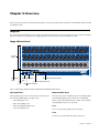
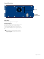
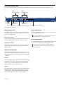
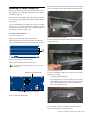
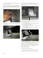
Stage 48
for VENUE Systems
PN 9320-65036-00 REV B 2/12
Legal Notices
This guide is copyrighted ©2012 by Avid Technology, Inc., (hereafter “Avid”),
with all rights reserved. Under copyright laws, this guide may not be duplicated
in whole or in part without the written consent of Avid.
003, 96 I/O, 96i I/O, 192 Digital I/O, 192 I/O, 888|24 I/O, 882|20 I/O, 1622 I/O,
24-Bit ADAT Bridge I/O, AudioSuite, Avid, Avid DNA, Avid Mojo, Avid Unity,
Avid Unity ISIS, Avid Xpress, AVoption, Axiom, Beat Detective, Bomb Factory,
Bruno, C|24, Command|8, Control|24, D-Command, D-Control, D-Fi, D-fx,
D-Show, D-Verb, DAE, Digi 002, DigiBase, DigiDelivery, Avid, Digidesign Audio
Engine, Digidesign Intelligent Noise Reduction, Digidesign TDM Bus, DigiDrive,
DigiRack, DigiTest, DigiTranslator, DINR, DV Toolkit, EditPack, Eleven,
EUCON, HD Core, HD Process, Hybrid, Impact, Interplay, LoFi, M-Audio,
MachineControl, Maxim, Mbox, MediaComposer, MIDI I/O, MIX, MultiShell,
Nitris, OMF, OMF Interchange, PRE, ProControl, Pro Tools M-Powered, Pro
Tools, Pro Tools|HD, Pro Tools|HD Native, QuickPunch, Recti-Fi, Reel Tape,
Reso, Reverb One, ReVibe, RTAS, Sibelius, Smack!, SoundReplacer, Sound
Designer II, Strike, Structure, SYNC HD, SYNC I/O, Synchronic, TL Aggro, TL
AutoPan, TL Drum Rehab, TL Everyphase, TL Fauxlder, TL In Tune, TL
MasterMeter, TL Metro, TL Space, TL Utilities, Transfuser, Trillium Lane Labs,
Vari-Fi, Velvet, X-Form, and XMON are trademarks or registered trademarks of
Avid Technology, Inc. Xpand! is Registered in the U.S. Patent and Trademark
Office. All other trademarks are the property of their respective owners.
Product features, specifications, system requirements, and availability are
subject to change without notice.
Guide Part Number 9320-65036-00 REV B 2/12
Documentation Feedback
We are always looking for ways to improve our documentation. If you have
comments, corrections, or suggestions regarding our documentation, email us
at [email protected].
Safety Compliance
Safety Statement
This equipment has been tested to comply with USA and Canadian safety
certification in accordance with the specifications of UL Standards: UL60065 7th
/IEC 60065 7th and Canadian CAN/CSA C22.2 60065:03. Avid Inc., has been
authorized to apply the appropriate UL & CUL mark on its compliant equipment.
Warning
Rack-Mount Safety Instructions
1) Elevated Operating Ambient - If installed in a closed or multi-unit rack
assembly, the operating ambient temperature of the rack environment might be
greater than room ambient. Therefore, consider installing the equipment in an
environment compatible with the maximum ambient temperature (Tma)
specified by the manufacturer.
2) Reduced Air Flow - Installation of the equipment in a rack should be such that
the amount of air flow required for safe operation of the equipment is not
compromised. Stage 48 airflow is from the front of the chassis enclosure to the
rear. Make allowances for cooling air to be available to the front panel surface
and no restrictions at the rear.
3) Mechanical Loading - Mounting of the equipment in the rack should be such
that ahazardous condition is not achieved due to uneven mechanical loading.
Important Safety Instructions
1) Read these instructions.
2) Keep these instructions.
3) Heed all warnings.
4) Follow all instructions.
5) Only perform the services explicitly described in the install and or user
manual. For services or procedures not outlined in the install or user manual,
speak with authorized service personnel.
6) Do not use this equipment near water.
7) Clean only with dry cloth.
8) Do not block any ventilation openings. Install in accordance with the
manufacturer’s instructions.
9) Do not install near any heat sources such as radiators, heat registers, stoves,
or other equipment (including amplifiers) that produce heat.
10) Do not defeat the safety purpose of the polarized or grounding-type plug. A
polarized plug has two blades with one wider than the other. A grounding type
plug has two blades and a third grounding prong. The wide blade or the third
prong are provided for your safety. If the provided plug does not fit into your
outlet, consult an electrician for replacement of the obsolete outlet.
11) Protect power cords from being walked on or pinched particularly at plugs,
convenience receptacles, and the point where they exit from the equipment.
12) Only use attachments/accessories specified by the manufacturer.
13) For products that are not rack-mountable: Use only with a cart, stand, tripod,
bracket, or table specified by the manufacturer, or sold with the equipment.
When a cart is used, use caution when moving the cart/equipment combination
to avoid injury from tip-over.
14) Unplug this equipment during lightning storms or when unused for long
periods of time.
15) Refer all servicing to qualified service personnel. Servicing is required when
the equipment has been damaged in any way, such as power-supply cord or
plug is damaged, liquid has been spilled or objects have fallen into the
equipment, the equipment has been exposed to rain or moisture, does not
operate normally, or has been dropped.
16) For products that are a Mains powered device:
The equipment shall not be exposed to dripping or splashing and no objects
filled with liquids (such as vases) shall be placed on the equipment.
Warning! To reduce the risk of fire or electric shock, do not expose this
equipment to rain or moisture.
17) For products containing a lithium battery:
CAUTION! Danger of explosion if battery is incorrectly replaced. Replace only
with the same or equivalent type.
18) The power inlet is the main disconnect device and should remain
accessible. Disconnect the power cord before servicing the unit.
19) The equipment shall be used at a maximum ambient temperature of 40° C.
20) Disconnect power from mains before opening the product (console and
Stage 48)
4) Circuit Overloading - Consideration should be given to the connection of the
equipment to the supply circuit and the effect that overloading of the circuits
might have on overcurrent protection and supply wiring. Appropriate
consideration of equipment nameplate ratings should be used when addressing
this concern.
5) Reliable Earthing - Reliable earthing of rack-mounted equipment should be
maintained. Particular attention should be given to supply connections other
than direct connections to the branch circuit (for example, use of power strips).
Contents
Chapter 1. Introduction . . . . . . . . . . . . . . . . . . . . . . . . . . . . . . . . . . . . . . . . . . . . . . . . . . . . . . . . . . . . . . . . . . . . . . . . . . . . . . 1
Stage 48 Features . . . . . . . . . . . . . . . . . . . . . . . . . . . . . . . . . . . . . . . . . . . . . . . . . . . . . . . . . . . . . . . . . . . . . . . . . . . . . 1
What’s Included . . . . . . . . . . . . . . . . . . . . . . . . . . . . . . . . . . . . . . . . . . . . . . . . . . . . . . . . . . . . . . . . . . . . . . . . . . . . . . . 1
Additional Required Components . . . . . . . . . . . . . . . . . . . . . . . . . . . . . . . . . . . . . . . . . . . . . . . . . . . . . . . . . . . . . . . . . . 1
Optional Components . . . . . . . . . . . . . . . . . . . . . . . . . . . . . . . . . . . . . . . . . . . . . . . . . . . . . . . . . . . . . . . . . . . . . . . . . . 1
Operational Requirements . . . . . . . . . . . . . . . . . . . . . . . . . . . . . . . . . . . . . . . . . . . . . . . . . . . . . . . . . . . . . . . . . . . . . . . 2
About www.avid.com . . . . . . . . . . . . . . . . . . . . . . . . . . . . . . . . . . . . . . . . . . . . . . . . . . . . . . . . . . . . . . . . . . . . . . . . . . . 2
Registration . . . . . . . . . . . . . . . . . . . . . . . . . . . . . . . . . . . . . . . . . . . . . . . . . . . . . . . . . . . . . . . . . . . . . . . . . . . . . . . . . . 2
Conventions Used in This Guide . . . . . . . . . . . . . . . . . . . . . . . . . . . . . . . . . . . . . . . . . . . . . . . . . . . . . . . . . . . . . . . . . . . 3
Chapter 2. Overview. . . . . . . . . . . . . . . . . . . . . . . . . . . . . . . . . . . . . . . . . . . . . . . . . . . . . . . . . . . . . . . . . . . . . . . . . . . . . . . . . 5
Stage 48 . . . . . . . . . . . . . . . . . . . . . . . . . . . . . . . . . . . . . . . . . . . . . . . . . . . . . . . . . . . . . . . . . . . . . . . . . . . . . . . . . . . . 5
Ethernet Snake Card . . . . . . . . . . . . . . . . . . . . . . . . . . . . . . . . . . . . . . . . . . . . . . . . . . . . . . . . . . . . . . . . . . . . . . . . . . . 8
Chapter 3. Connecting Stage 48 . . . . . . . . . . . . . . . . . . . . . . . . . . . . . . . . . . . . . . . . . . . . . . . . . . . . . . . . . . . . . . . . . . . . . . . 9
Setting the Device ID . . . . . . . . . . . . . . . . . . . . . . . . . . . . . . . . . . . . . . . . . . . . . . . . . . . . . . . . . . . . . . . . . . . . . . . . . . . 9
Connecting and Powering Up . . . . . . . . . . . . . . . . . . . . . . . . . . . . . . . . . . . . . . . . . . . . . . . . . . . . . . . . . . . . . . . . . . . . . 9
Confirming I/O . . . . . . . . . . . . . . . . . . . . . . . . . . . . . . . . . . . . . . . . . . . . . . . . . . . . . . . . . . . . . . . . . . . . . . . . . . . . . . . 10
Chapter 4. Configuring and Installing I/O in Stage 48 . . . . . . . . . . . . . . . . . . . . . . . . . . . . . . . . . . . . . . . . . . . . . . . . . . . . 11
Configuring Remote I/O . . . . . . . . . . . . . . . . . . . . . . . . . . . . . . . . . . . . . . . . . . . . . . . . . . . . . . . . . . . . . . . . . . . . . . . . 11
Removing I/O Cards from SC48 . . . . . . . . . . . . . . . . . . . . . . . . . . . . . . . . . . . . . . . . . . . . . . . . . . . . . . . . . . . . . . . . . . 12
Installing I/O Cards in Stage 48 . . . . . . . . . . . . . . . . . . . . . . . . . . . . . . . . . . . . . . . . . . . . . . . . . . . . . . . . . . . . . . . . . . 15
Installing Stage 48 in a Rack . . . . . . . . . . . . . . . . . . . . . . . . . . . . . . . . . . . . . . . . . . . . . . . . . . . . . . . . . . . . . . . . . . . . 17
Chapter 5. Specifications . . . . . . . . . . . . . . . . . . . . . . . . . . . . . . . . . . . . . . . . . . . . . . . . . . . . . . . . . . . . . . . . . . . . . . . . . . . 19
Supported Stage I/O Card Audio Specifications . . . . . . . . . . . . . . . . . . . . . . . . . . . . . . . . . . . . . . . . . . . . . . . . . . . . . . . 19
Stage 48 Mechanical Specifications . . . . . . . . . . . . . . . . . . . . . . . . . . . . . . . . . . . . . . . . . . . . . . . . . . . . . . . . . . . . . . . 20
Power and Status LED Indicators . . . . . . . . . . . . . . . . . . . . . . . . . . . . . . . . . . . . . . . . . . . . . . . . . . . . . . . . . . . . . . . . . 21
Appendix A. Compliance Information . . . . . . . . . . . . . . . . . . . . . . . . . . . . . . . . . . . . . . . . . . . . . . . . . . . . . . . . . . . . . . . . . 23
Environmental Compliance . . . . . . . . . . . . . . . . . . . . . . . . . . . . . . . . . . . . . . . . . . . . . . . . . . . . . . . . . . . . . . . . . . . . . . 23
EMC (Electromagnetic Compliance) . . . . . . . . . . . . . . . . . . . . . . . . . . . . . . . . . . . . . . . . . . . . . . . . . . . . . . . . . . . . . . . 23
Contents v
Chapter 1: Introduction
VENUE Stage 48 from Avid ® is a configurable remote stage box
for VENUE SC48 consoles that uses highly reliable, low-latency, and fully redundant Ethernet audio snake connections.
Up to two Stage 48 units can be connected to an Ethernet
Snake card-equipped SC48 console. All digital and analog remote I/O are digitally controlled, fully recallable and fully
routable from your console.
If you purchased an SC48 Remote system, a fully loaded
Stage 48 is included and provides 32 remote Stage inputs and
16 remote Stage outputs (two AI16 Analog Input cards and one
AO16 Analog Output card).
You can also purchase an empty Stage 48 and expand your system’s remote I/O capabilities by installing compatible VENUE
Stage I/O cards in Stage 48 (up to the maximum Stage I/O capacity of SC48–48 input channels and 32 output channels of
combined local and remote Stage I/O).
Stage 48 Features
A single Stage 48 supports up to 48 channels of remotely located Stage I/O. Up to two Stage 48 units can be used simultaneously supporting the maximum Stage I/O capacity of SC48
systems (48 input channels and 32 output channels of combined local and remote Stage I/O).
A single Stage 48 provides the following:
• Up to 48 channels of remote Stage I/O to SC48 systems
• Compatibility with SC48 Stage I/O cards such as AI16 Analog Input cards, AO16 Analog Output cards, XO16 Analog/Digital Output cards, and AT16 A-Net Output cards
What’s Included
• Stage 48 remote stage box
• One (1) IEC power cable, North American standard
• Four (4) rear rack brackets (recommended for rear support when mounting a Stage 48 in standard 19” rack)
• Four (4) extenders and eight (8) Phillips head screws for
installing compatible output cards in Stage 48
• Stage 48 Guide
• Stage 48 Quick Setup Guide
• Health and Safety Guide
• Registration Card
Additional Required Components
• Shielded Cat5e or better Ethernet cable with Neutrik
etherCON connectors for the primary digital snake
connection
• An Ethernet Snake card installed in SC48 (pre-installed in
SC48 Remote)
The Ethernet Snake card can only be installed by Avidauthorized service personnel.
Optional Components
• A second shielded Cat5e or better Ethernet cable with
Neutrik etherCON connectors for the redundant snake connection
• Primary and redundant Ethernet digital snake connections, with automatic snake failover in the event of connection failure
• Locking Neutrik etherCON ® RJ45 ports
• Front-panel Power and Status LED indicators
Chapter 1: Introduction 1
Operational Requirements
About www.avid.com
Temperature and Ventilation
The Avid website (www.avid.com) is your best online source
for information to help you get the most out of your system.
The following are just a few of the services and features available.
VENUE devices should be operated away from heat sources
and with adequate ventilation. Status and warnings are provided for temperature, power and other factors by the Power
and Status LEDs located on the front panel of Stage 48.
Storage
The Stage 48 should be stored and transported at temperatures not lower than 0 degrees F (–18 degrees C) and not exceeding 140 degrees F (60 degrees C).
Operation
The Stage 48 should be operated at temperatures not lower
than 40 degrees F (4 degrees C) and not exceeding 104
degrees F (40 degrees C).
Water and Moisture
The Stage 48 should be operated away from sources of direct
moisture and should be kept clear of liquids that might spill
into the device. If condensation is present on the device, leave
the device to dry in ambient air for at least one hour before
powering the device on.
Cleaning and Maintenance
Product Registration Register your purchase online.
Support and Downloads Contact Customer Success (technical
support); download software updates and the latest online
manuals; browse the Compatibility documents for system requirements or search the online Knowledgebase.
Training and Education Study on your own using courses
available online or find out how you can learn in a classroom
setting at a certified Avid training center.
Products and Developers Learn about Avid
products; download demo software or learn about our Development Partners and their plug-ins, applications, and hardware.
News and Events Get the latest news from Avid or sign up for
a product demo.
Pro Tools Accelerated Videos Watch the series of free tutorial
videos. Accelerated Videos are designed to help you get up and
running with Pro Tools and its plug-ins quickly.
Live Sound Webinars Watch free tutorial videos and
VENUE-specific webinars to learn from the experts.
If you need to clean the surface of the Stage 48, use a dry cloth.
Do not apply any cleaning solutions, spray cleaners, or abrasives to the surface.
To learn more about these and other resources available from
Avid, visit our website (www.avid.com).
Power Connections
Registration
The power supply in the Stage 48 requires its own power connection. The power supply is auto voltage-selecting (100VAC
to 240VAC). A modular IEC power cable is provided for power
connections.
Review the enclosed Registration Information Card and follow
the instructions on it to quickly register your purchase online.
By registering, you become eligible to receive the following:
• Technical support information
• Software update and upgrade notices
• Hardware warranty information
2
Stage 48
Conventions Used in This Guide
All of our guides use the following conventions to indicate
menu choices and key commands:
Convention
Action
Options > System
In the VENUE software, click
Options to display the Options
page, then click the System tab.
File > Save
Choose Save from the File menu
Control+N
Hold down the Control key and
press the N key
Control-click
Hold down the Control key and click
the mouse button
Right-click
Click with the right mouse button
The names of Commands, Options, and Settings that appear
on-screen are in a different font.
The following symbols are used to highlight important information:
User Tips are helpful hints for getting the most from your
system.
Important Notices include information that could affect
your data or the performance of your system.
Shortcuts show you useful keyboard or mouse shortcuts.
Cross References point to related sections in this guide and
other VENUE guides.
Chapter 1: Introduction 3
4
Stage 48
Chapter 2: Overview
This section describes the front and back panel features of Stage 48, and the front panel features of the Ethernet Snake card that
is installed in SC48.
Stage 48
If you purchased an SC48 Remote system, a fully populated Stage 48 with two AI16 Analog Input cards and one AO16 Analog Output card is included. If you purchased an empty Stage 48, no I/O cards are present in the I/O card section.
Stage 48 Front Panel
I/O card
section
2
6
Act and Sig
LEDs
5
7
4
0
3
1
Redundant snake port (Port B)
Status ID Switch
LED
Primary snake port (Port A)
Power
LED
Recessed Pushbutton
Figure 1. Stage 48 (fully populated version included with SC48 Remote systems shown)
I/O Card Section
Ethernet Snake Ports
The Stage 48 I/O card section consists of three slots that accept
the following VENUE input and output cards:
The Stage 48 provides two Ethernet ports for making primary
and redundant digital snake connections to the Ethernet
Snake card in SC48. Shielded Cat5e or better cable with Neutrik etherCON connectors are required.
• AI16 Analog Input card
• AO16 Analog Output card
• XO16 Analog/Digital Output card
• AT16 A-Net Output card
Port A
Port A is used for the primary snake connection.
Port B
Port B is used for the redundant snake connection.
Chapter 2: Overview 5
Snake Act and Sig LEDs
Power and Status LED Indicators
Each primary and redundant snake connection has its own Activity (Act) and Signal (Sig) LEDs. The system is ready for use
when all Stage 48 units are connected and all Act and Sig LEDs
are lit solid.
The Power and Status LEDs light green, yellow, or red to indicate the status of Stage 48.
Act LED
The Act (activity) LED lights solid to indicate that AVB Ethernet traffic is currently active on the connected Snake. If a redundant snake is connected, then both primary and redundant Act LEDs will be lit for each Stage 48.
Sig LED
The Sig (signal) LED lights solid to indicate that a valid communication connection exists between the Stage 48 and console. If a redundant snake is connected, then both primary and
redundant Sig LEDs will be lit for each Stage 48.
If the Sig LED does not light after you have connected a
Stage 48, make sure the ID switches on any connected
Stage 48 units are set properly.
ID Switch
The ID switch sets the internal ID of the Stage 48. Select 1
when connected to ports labeled “Stage 1” on the SC48 Ethernet Snake card. When using two Stage 48 units, set the ID
switch to 2 on the second Stage 48 (the Stage 48 connected to
the port labeled “Stage 2” on the SC48 Ethernet Snake card).
6
Stage 48
See “Power and Status LED Indicators” on page 21 for
more information on Stage 48 Power and Status LED
codes.
Recessed Pushbutton
The Recessed Pushbutton either resets the Stage 48 or initiates a firmware update, depending on how long the button is
held when pressed:
• Pressing and holding the Recessed Pushbutton between
one (1) and five (5) seconds resets Stage 48. Use this to
power cycle Stage 48 if the power switch is inaccessible.
• Pressing and holding the Recessed Pushbutton for at least
five (5) seconds puts Stage 48 in firmware update mode.
The Status LED flashes green.
If you have entered firmware update mode by accident,
you can reset Stage 48 by power cycling the unit using the
back panel Power switch.
Check www.avid.com/support for VENUE support, including Stage 48 firmware downloads and firmware update instructions.
Stage 48 Back Panel
Fan vents
Power switch
AC power connector
Figure 2. Stage 48 back panel
Power Switch
The Power switch applies power to the Stage 48.
AC Power Connector
The AC power connector accepts a standard IEC AC power cable. The Stage 48 is auto-power selecting (100VAC to
240VAC). It automatically works with a standard modular
power cable when connected to an AC receptacle in any country.
Stage 48 airflow is from the front and sides of the chassis
enclosure to the back. Do not block the fan vents on the
back panel of Stage 48.
Chapter 2: Overview 7
Ethernet Snake Card
This section describes the front-panel features of the Ethernet Snake card. The Ethernet Snake card is installed in SC48.
Stage 1
Act and Sig LEDs
Status LED
Stage 1 primary
snake port
Recessed pushbutton
Stage 2
Act and Sig LEDs
Stage 2 primary
snake port
Stage 1 redundant snake port
Stage 2 redundant snake port
Figure 3. Ethernet Snake Card
Ethernet Snake Ports
Status LED Indicator
The Ethernet Snake card provides two pairs of Ethernet ports
for making primary and redundant digital snake connections
to up to two Stage 48 units.
The Status LED lights green, yellow, or red to indicate the status of the Ethernet Snake card.
Stage 1 Ports A and B
Port A is used for the primary snake connection and port B is
for the redundant snake connection to the first Stage 48.
Stage 2 Ports A and B
When using a second Stage 48, Stage 2 port A is used for the
primary snake connection and port B is for the redundant
snake connection.
Snake Act and Sig LEDs
Each primary and redundant snake connection has its own Activity (Act) and Signal (Sig) LED. The system is ready for use
when all Stage 48 units are connected and all Act and Sig LEDs
are lit solid.
Act LED
The Act LED lights solid to indicate that AVB Ethernet traffic
is currently active on the connected Snake. If a redundant
snake is connected, then both primary and redundant Act
LEDs will be lit for each connected Stage 48.
Sig LED
The Sig LED lights solid indicates that a valid communication
connection exists between the Stage 48 and console. If a redundant snake is connected, then both primary and redundant Sig LEDs will be lit for each connected Stage 48.
8
Stage 48
See “Status LED Indicator” on page 21 for more information Ethernet Snake card Status LED codes.
Recessed Pushbutton
Pressing and holding the Recessed Pushbutton for at least five
(5) seconds puts Stage 48 into firmware update mode.
Check www.avid.com/support for VENUE support, including Stage 48 firmware downloads and firmware update instructions.
Chapter 3: Connecting Stage 48
This section describes how to connect and power up the components of your system, and how to confirm your system’s
available Stage I/O.
Connecting and Powering Up
Primary and redundant snake connections are made using
Ethernet cables.
Setting the Device ID
Do not power up SC48 or any Stage 48 units before making
Ethernet snake connections. After connecting the snakes, it
is important to follow the proper power up sequence.
Before connecting and powering up your system, you must set
your the device ID of any Stage 48 units you will be connecting
to SC48.
To make snake connections and power up your system:
1
To set the Stage 48 device ID:
• For the primary snake connection, connect an Ethernet
cable from the Stage 1 A port on the Ethernet Snake card
in SC48 to the port A on Stage 48.
On the first Stage 48, using a small flathead screwdriver set
the ID switch to position 1.
1
On the second Stage 48, using a small flathead screwdriver
set the ID Switch to position 2.
2
• For the redundant snake connect a cable from the Stage 2
B port on the Ethernet Snake card in SC48 to port B on
Stage 48.
0
0
7
6
5
6
Stage 48 ID switch set to position 1 (left) and 2 (right)
SC48
To connect a second Stage 48, do the following:
• For the primary snake connect an Ethernet cable from the
Stage 2 A port on the Ethernet Snake card in SC48 to the
port A on Stage 48.
5
ID
2
4
7
2
• To make an optional redundant connection, connect an
Ethernet cable from the Stage 1 B port on the Ethernet
Snake card in SC48 to the port B on Stage 48.
3
4
ID
1
3
2
1
For the first Stage 48, do the following:
Primary snake
Primary snake
Redundant
snake
2
3
0
4
0
7
5
6
7
2
3
4
1
5
1
Redundant snake
Stage 48 (2)
6
Stage 48 (1)
ID switch set to position 1
ID switch set to position 2
Ethernet
Snake
Figure 4. Connecting Stage 48 primary and redundant snake connections
Chapter 3: Connecting Stage 48 9
3 Connect the included IEC power cable(s) between the Power
connector(s) on any Stage 48 units present and your power
source.
4 Press the Power switch on the first Stage 48 to power on the
device. The Status LED indicator is lit solid yellow while the
Stage 48 initializes.
If applicable, for the second Stage 48 connect power and
power on the device.
5
Wait for the Stage 48(s) to initialize. Initialization is complete when the Power and Status LEDs on the Stage 48 front
panel are lit solid green.
6
A flashing red Power LED indicates a potential power problem. Power down, unplug Stage 48, and verify the power
source. See “Recessed Pushbutton” on page 6 for information on LED indicator codes.
Power on SC48 and wait for the Ethernet Snake card to initialize, indicated by a lit green Status LED. Audio will not pass
until the SC48 is fully initialized.
7
Both the Act and Sig LEDs on Stage 48 (s) and the Ethernet
Snake card in SC48 should be lit for all connected Ethernet
snakes.
8
If the Sig LED does not light after you have connected a
Stage 48, make sure the ID switches on all connected
Stage 48 units are set properly.
9
You should now confirm your I/O in VENUE.
Confirming I/O
After making snake connections and powering up your system, you can confirm your system’s available Stage I/O.
To confirm I/O in your system:
Go to Options > Devices to view your system hardware status.
The newly installed hardware should be displayed. All local
and remote Stage I/O appears in the SC48 Stage I/O slots in the
graphic.
1
Detail of Options > Devices page showing installed I/O
2 Go to the Patchbay page and click the Stage tab to verify that
the inputs and/or outputs are available in the Patchbay.
10
Stage 48
Chapter 4: Configuring and Installing I/O in Stage 48
This section shows how to configure remote I/O, and how to
install compatible VENUE Stage I/O cards in Stage 48. The following Stage I/O cards are compatible with Stage 48.
• AI16 Analog Input card
Example Configurations
The example configurations described in this section are
based on an SC48 with the following local Stage I/O:
• AO16 Analog Output card
• Three AI16 Input cards (installed in SC48 slots A, B,
and C)
• XO16 Analog/Digital Output card
• Two AO16 output cards (installed in SC48 slots D and E)
• AT16 A-Net Output card
The VENUE IO16 Option card cannot be installed Stage 48.
Configuring Remote I/O
How you configure the I/O in a Stage 48 depends on the configuration of your current system.
Adding a Second Stage 48 to an
SC48 Remote System
You can expand the Stage I/O capacity of your SC48 Remote
system by adding a second Stage 48 and installing compatible
Stage I/O cards in it. SC48 Remote systems support up to the
maximum Stage I/O capacity of SC48–48 input channels and
32 output channels of combined local and remote Stage I/O.
Converting a Standard SC48 to an
SC48 Remote
If you have a standard SC48 console, it can be converted to an
SC48 Remote system. Converting your SC48 lets you connect
your SC48 to up to two Stage 48 units. In order to convert your
SC48, the top two AI16 input cards must be removed from
your console. These cards can then be installed in Stage 48.
You can choose to also relocate any other compatible Stage I/O
cards from SC48 to up to two Stage 48 units.
This SC48 could be reconfigured as an SC48 Remote system in
the following ways:
• Relocate all SC48 Stage I/O to two Stage 48 units. Install
all three input cards in one Stage 48 and both output
cards in a second Stage 48. Remaining SC48 local I/O consists of FOH inputs and outputs.
• Relocate the first two AI16 input cards (corresponding to
Stage input channels 1–32) and the AO16 output card located in Slot E (corresponding to Stage output channels
17–32) to a single Stage 48. Because of installation requirements, the remaining local AI16 input card is located in slot C of SC48, corresponding to Stage input
channels 33–48. The remaining local AO16 output card is
located in slot D of SC48, corresponding to Stage output
channels 1–16.
• Relocate all three AI16 input cards to a single Stage 48,
and leave both output cards in SC48. All Stage inputs for
the system are located remotely in a single Stage 48, and
all Stage outputs are located locally in SC48.
These are only example configurations. Other configurations are possible. The only requirement is that the top two
AI16 output cards must be removed when converting an
SC48 to an SC48 Remote system.
Converting an SC48 to an SC48 Remote system can only be
done by Avid-authorized service personnel. However, owners are authorized to remove Stage I/O cards from SC48 and
install them into Stage 48.
Chapter 4: Configuring and Installing I/O in Stage 48 11
Removing I/O Cards from SC48
SC48 Stage I/O cards that you want to relocate to one or to two
Stage 48 units can be removed from SC48 prior to sending it to
an Avid-authorized service technician. You can then install
these cards in Stage 48.
Removing AI16 Input Cards
In order to convert your SC48 to an SC48 Remote system, the
first two AI16 input cards (installed in slots A and B of the
console) must be removed.
To remove AI16 cards:
1
Shut down your system, and turn off power to the SC48.
Figure 3. Correct alignment of Top Panel slot and pivot post
To lock the Top Panel in the vertical position, tighten the two
interior captive thumbscrews located on the top left and top
right sides of the console.
5
2 Disconnect any power cables from SC48, as well as any other
audio cables and peripherals attached to the console.
Remove all screws that secure the Top Panel to the console
chassis.
3
Figure 1. Removing the 26 Top Panel screws
Hold the front edge of the Top Panel and carefully lift it upwards to a vertical position.
4
Figure 4. Tightening the top left captive thumbscrew
6
If you sense any resistance when lifting the Top Panel upwards, do not force it. The Top Panel has slots that pivot on
posts attached to the sides of the console chassis (Figure 3).
Removing the Top Panel screws may cause the Top Panel to
slide towards the front of the console so that the Top Panel
slots are not correctly aligned with the posts. If this occurs,
slide or push the Top Panel towards the rear of the console
before lifting, making sure the posts are correctly aligned
with the slots.
Locate the card installed in slot A of the console.
7 Disconnect the 50-pin ribbon cable by pushing the retaining
clips outwards.
Figure 2. Lifting the Top Panel to vertical
Figure 5. Disconnecting the 50-pin ribbon cable
The disconnected ribbon cable is left in the console. Do not
attempt to remove it.
12
Stage 48
8
Removing an Output Card
Loosen the two interior captive thumbscrews that secure the
card to the console chassis.
Output cards can be removed from SC48 and installed in
Stage 48. The following procedure shows how to remove an
output card from slot D of SC48.
Mark the cable end “A.” This will allow the cable to be easily
identified when the Ethernet Snake card is installed.
9
To remove an AO16 card:
1
Shut down your system, and turn off power to SC48.
2 Disconnect any power cables from SC48, as well as any other
audio cables and peripherals attached to the console.
Remove the 26 screws that secure the Top Panel to the console chassis.
3
Figure 6. Loosening the captive thumbscrews
On the back of the console, remove the four screws that secure the card to the console chassis.
10
11 Gently slide the card out of the slot. If necessary, use a
flat-edged tool to pry the card away from the chassis.
Do not pry the card from the top. Doing so can damage the
copper strips located along the top of the card.
Figure 8. Removing the 26 Top Panel screws
Hold the front edge of the Top Panel and carefully lift it upwards to a vertical position.
4
If you sense any resistance when lifting the Top Panel upwards, do not force it. The Top Panel has slots that pivot on
posts attached to the sides of the console chassis
(Figure 10). Removing the Top Panel screws may cause the
Top Panel to slide towards the front of the console so that
the Top Panel slots are not correctly aligned with the posts.
If this occurs, slide or push the Top Panel towards the rear
of the console before lifting, making sure the posts are correctly aligned with the slots.
Figure 9. Lifting the Top Panel to vertical
Figure 7. Removing the card from the slot
12 Repeat the procedure to remove the card from slot B of the
console. Mark the cable end “B.”
13 If required, repeat to remove the card from slot C. Mark the
cable end “C.”
If you are finished removing cards, do the following to close
and secure the Top Panel:
14
• Loosen the captive thumbscrews and carefully lower the
Top Panel into position.
• Replace the screws that secure the Top Panel to the console chassis.
Figure 10. Correct alignment of Top Panel slot and pivot post
Chapter 4: Configuring and Installing I/O in Stage 48 13
To lock the Top Panel in the vertical position, tighten the two
interior captive thumbscrews located on the top left and top
right sides of the console.
5
On the back of the console, remove the four screws that secure the card to the console chassis.
8
Gently slide the card out of the slot. If necessary, use a
flat-edged tool to pry the card away from the chassis.
9
Do not pry the card from the top. Doing so can damage the
copper strips located along the top of the card.
Figure 11. Tightening the top left captive thumbscrew
Locate the card in slot D and loosen the two interior captive
thumbscrews that secure the card to the console chassis.
6
Figure 14. Removing the card from the slot
10
If required, repeat to remove the card from slot E.
11 If you are finished removing cards, do the following to close
and secure the Top Panel:
• Loosen the captive thumbscrews and carefully lower the
Top Panel into position.
• Replace the screws that secure the Top Panel to the console chassis.
Figure 12. Loosening the captive thumbscrews
7 Disconnect the 50-pin ribbon cable by pushing the retaining
clips outwards.
Figure 13. Disconnecting the 50-pin ribbon cable
Leave the disconnected ribbon cable in the console. Do not
attempt to remove it. Tuck the unconnected end of the cable
and any excess cabling in the gap along the inner right side
of the console.
14
Stage 48
Carefully pull the panel partially away from the rack, making
sure not to damage the fan cable attached to the back panel.
5
Installing I/O Cards in Stage 48
After you have removed Stage I/O cards from SC48, or if you
have purchased new compatible Stage I/O cards, you can install them in Stage 48.
Stage 48 has three slots that accept Stage I/O cards. I/O cards
are connected to pre-installed 50-pin ribbon cables located inside Stage 48.
It is recommended that you install cards in Stage 48 starting
with the top slot. If you are installing a combination of input
and output cards in one Stage 48, it is recommended that you
install input cards above output cards.
To install I/O cards in Stage 48:
1
Power down Stage 48.
2
Remove power and audio cables from Stage 48.
Figure 17. Removing the back panel.
On the front panel of Stage 48, locate the slots which you
want to install I/O cards into, and remove the card slot covers.
3
6 Disconnect the fan cable before removing the panel entirely.
Set the panel aside.
I/O
card
slots
2
3
4
5
7
0
1
6
Figure 15. An empty Stage 48’s I/O card slots
4
Remove the ten back panel mounting screws.
Do not remove the four fan mounting screws that are closest
to the fan port.
Disconnecting the fan cable
Mounting screws (remove all)
If you are installing output cards in Stage 48, do the following before proceeding:
7
• Locate the included extenders.
• For each output card, use two extenders and two of the included Phillips head screws to attach the extenders to the
back of the card. Orient the extenders so that the long
side of the extenders lay flat.
Fan mounting screws (do not remove)
Figure 16. Stage 48 I/O back panel
Figure 18. AO16 Output card with extenders
For each I/O card you are installing, hold the card by its
edges and gently slide the card into the slot.
8
Chapter 4: Configuring and Installing I/O in Stage 48 15
Secure each card to the front panel of Stage 48 using four
front panel mounting screws.
9
Inside Stage 48 via the open back panel, tighten the two
captive thumbscrews to secure the I/O card to the Stage 48
chassis. Use a screwdriver to make sure the card is properly secured.
10
Cut the cable tie that is securing the ribbon cable bundle,
making sure to not damage the ribbon cables. Remove the cable tie from Stage 48.
12
Figure 21. Cable tie to be removed
Use the following cables, depending on the slots you have
chosen to install cards into:
13
Figure 19. Tightening a captive thumbscrew
Inside Stage 48, locate the pre-installed 50-pin I/O card ribbon cable bundle.
• For a card installed in the top slot of Stage 48, use the cable that is labeled in Figure 22 as “1.”
11
• For a card installed in the middle slot, use the cable that
is labeled in Figure 22 as “2.”
• For a card installed the bottom slot, use the cable that is
labeled in Figure 22 as “3.”
11
22
33
Figure 20. I/O card ribbon cable bundle (front view)
Figure 22. I/O card ribbon cables
Connect the cable to the I/O card by making sure the plastic
key on the connector is aligned with the slot on the port. Secure the connection by moving the retaining clips on each side
of the socket connector inward. Check to make sure the ribbon
cable is connected securely.
14
15
Reconnect the fan cable.
16
Replace the back panel of Stage 48.
To connect your Stage 48 to your SC48 and to confirm I/O
card installation, proceed to Chapter 3, “Connecting Stage 48.”
17
16
Stage 48
Installing Stage 48 in a Rack
Stage 48 can be installed in a standard 19-inch rack. When installing Stage 48 in a rack, it is recommended that you install
the included rear brackets for stability. Your rack must be
equipped with rear rack rails.
Make allowances for cooling air to be available to the
front panel surface side vents of the chassis enclosure.
There should also be no restrictions at the back of the
unit, especially around the back panel fan vents.
To install Stage 48 in a rack:
1
Slide Stage 48 into the rack.
Secure the front of Stage 48 to the rack using rack screws
(not included).
2
3 Using the included rear brackets, on the back of the rack line
up the bracket screw holes to the rack’s rear rails so that
Stage 48 sits on the rear bracket flanges.
Attach the rack brackets to the rear rack rails using rack
screws.
4
Chapter 4: Configuring and Installing I/O in Stage 48 17
18
Stage 48
Chapter 5: Specifications
Supported Stage I/O Card Audio Specifications
AI16 Analog Input Card
Parameter
Specifications
Type
Balanced, XLR3-Female
Gain
Limit
Units
Condition/Comment
+10 to +60
dB
6 dB analog steps with 0.1 dB digital increments and crossfade at
analog relay switch point
Max Input Level
+32
dBu
Pad ON
Pad
20
dB
Input Impedance, pad OFF
5.5k
Ohm
Each leg to ground
Input Impedance, pad ON
3.8k
Ohm
Each leg to ground
Phantom Power
+48
VDC
10 mA max per channel
EIN
-126
dBu
Max gain, 150 ohm source,
20 Hz-20 kHz BW, unweighted
THD + N
0.003
%
Minimum gain, pad OFF, –1 dBFS
output, 20 HZ – 20 kHz BW
A/D Converter Latency
0.25
ms
Fs=48kHz
max
All measurements at Fs=48 kHz with 150 Ohm source impedance and 600 Ohm load impedance, unless otherwise specified.
0 dBU = 0.775Vrms.
AO16 Analog Input Card
Parameter
Specifications
Type
Balanced, XLR3-Male
Impedance
50
Maximum Output Level
+24
D/A Converter Latency
0.58
Limit
max
Units
Condition/Comment
Ohm
Each leg to ground
dBu
ms
Fs=48kHz
Chapter 5: Specifications 19
XO16 Analog/Digital Output Card
XO16 Analog Line Outputs
Parameter
Specifications
Type
Balanced, XLR3-Male
Impedance
50
Maximum Output Level
+24
D/A Converter Latency
0.58
Limit
max
Units
Condition/Comment
Ohm
Each leg to ground
dBu
ms
Fs=48kHz
Units
Condition/Comment
Each leg to ground
XO16 Digital Outputs
Parameter
Specifications
Limit
Type
Balanced, XLR3-Male
Format
AES3 (IEC-60958 Type I)
Impedance
110
Ohm
Word Length
24
bit
Sample Rate
48
kHz
Sample Rate Conversion
None
Dithering
None
Channel Status Info
Pro, Audio 48K, No Emphasis
Max Cable Length
100
meter
Without equalization, 110 Ohm
cable
All measurements at Fs=48 kHz with 150 Ohm source impedance and 600 Ohm load impedance, unless otherwise specified.
0 dBU = 0.775Vrms.
Stage 48 Mechanical Specifications
Stage 48 Specifications
20
Dimensions (H x W x D)
8.75 x 17.05 x 18 inches (222 x 433 x 455 mm) without ears
8.75 x 19 x 18 inches (222 x 481 x 455 mm) with ears
Rack Spaces
5U
Stage I/O Card Slots
3
Weight
Empty: 30lb (13.5kg)
Full: 42.5lb (19.3kg)
Power Requirements
100–240 VAC, 50–60 Hz, 140 W
Primary and Redundant Snake Connectors
RJ45 Neutrik etherCON (2)
Snake Cable Type
Shielded Cat5e or better (Neutrik etherCON connectors required)
Max Snake Cable Length
100 metre (323 feet)
Stage 48
Power and Status LED Indicators
Status LED Indicator
Power LED Indicator
(Stage 48 and Ethernet Snake Card)
(Stage 48 Only)
The Status LEDs on the Ethernet Snake Card and the Stage 48
light to indicate status as follows:
The Power LED lights to indicated the power status of Stage 48
as follows:
Status LED
Power LED
Status LED
Indicates
Status LED
Indicates
Green solid
Initialization is complete and the device is
ready to pass audio.
Green solid
A green solid Power LED indicates that
Stage 48 is powered on and ready for use.
Yellow solid
The device is initializing. No audio passes
during initialization.
Red flashing
A red flashing Power LED indicates a
Stage 48 voltage problem alert. Power down
Stage 48 and verify the power source.
Red solid
The device has failed to initialize. Power
down the device, then restart.
Yellow solid
A solid yellow Power LED indicates a
Stage 48 fan failure. Power down the unit,
disconnect power, remove the back panel,
and make sure the fan cable is properly connected (see “Installing I/O Cards in Stage
48” on page 15 for instructions).
Yellow flashing
A yellow flashing Power LED indicates a
Stage 48 power supply temperature alert.
This may indicate that the device is overheating. Power down Stage 48 and check
that the unit is properly ventilated.
Green flashing
A firmware update for the device is in progress. No audio passes during a firmware
update.
Red flashing
A firmware update has failed. Check connections to the computer and retry the
update.
Yellow flashing
A Stage 48 or Ethernet Snake card circuit
board temperature alert. Power down the
device and check that the back of the device
is properly ventilated
Chapter 5: Specifications 21
22
Stage 48
Appendix A: Compliance Information
Environmental Compliance
Disposal of Waste Equipment by Users in the
European Union
This symbol on the product or its packaging indicates that this product must not
be disposed of with other waste. Instead, it is your responsibility to dispose of
your waste equipment by handing it over to a designated collection point for the
recycling of waste electrical and electronic equipment. The separate collection
and recycling of your waste equipment at the time of disposal will help conserve
natural resources and ensure that it is recycled in a manner that protects human
health and the environment. For more information about where you can drop off
your waste equipment for recycling, please contact your local city recycling
office or the dealer from whom you purchased the product.
Proposition 65 Warning
This product contains chemicals, including lead, known to
the State of California to cause cancer and birth defects or
other reproductive harm. Wash hands after handling.
FCC Compliance for United States
Radio and Television Interference
Communication Statement
NOTE: This equipment has been tested and found to
comply with the limits for a Class B digital device, pursuant
to Part 15 of the FCC Rules. These limits are designed to
provide reasonable protection against harmful interference
in a residential installation. This equipment generates, uses,
and can radiate radio frequency energy and, if not installed
and used in accordance with the instructions, may cause
harmful interference to radio communications. However,
there is no guarantee that interference will not occur in a
particular installation. If this equipment does cause harmful
interference to radio or television reception, which can be
determined by turning the equipment off and on, the user is
encouraged to try and correct the interference by one or
more of the following measures:
• Reorient or locate the receiving antenna.
• Increase the separation between the equipment and
receiver.
• Connect the equipment into an outlet on a circuit
different from that to which the receiver is connected.
• Consult the dealer or an experienced radio/TV
technician for help.
Any modifications to the unit, unless expressly approved by
Avid, could void the user's authority to operate the
equipment.
Australian Compliance
Perchlorate Notice
This product may contain a lithium coin battery. The State of California requires
the following disclosure statement: “Perchlorate Material – special handling may
apply, See www.dtsc.ca.gov/hazardouswaste/perchlorate.”
Recycling Notice
Canadian Compliance
This Class B digital apparatus meets all requirements of the Canadian
Interference-Causing Equipment Regulations.
Cet appareil numérique de la classe B respecte toutes les exigences du
Règlement sur le material brouilleur du Canada.
CE Compliance
EMC (Electromagnetic Compliance)
Avid declares that this product complies with the following standards regulating
emissions and immunity:
• FCC Part 15 Class B
• EN 55103-1 E2, E3
• EN 55103-2 E2, E3
• AS/NZS CISPR 22 Class B
• CISPR 22 Class B
(EMC and Safety)
Avid is authorized to apply the CE (Conformité Europénne) mark on this
compliant equipment thereby declaring conformity to EMC Directive
2004/108/EC and Low Voltage Directive 2006/95/EC.
Korean EMC Regulations
23
Avid
Technical Support (USA)
Product Information
2001 Junipero Serra Boulevard
Daly City, CA 94014-3886 USA
Visit the Online Support Center at
www.avid.com/support
For company and product information,
visit us on the web at www.avid.com


![Stage 48 - akmedia.[bleep]digidesign.](http://vs1.manualzilla.com/store/data/007247961_1-0fc36f720a3108317a47260e3de3799a-150x150.png)