1
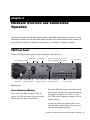
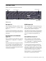
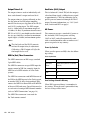
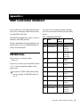
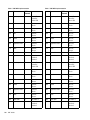
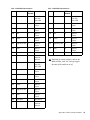
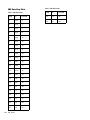
PRE™ Guide Version 9.0 Legal Notices This guide is copyrighted ©2010 by Avid Technology, Inc., (hereafter “Avid”), with all rights reserved. Under copyright laws, this guide may not be duplicated in whole or in part without the written consent of Avid. 003, 96 I/O, 96i I/O, 192 Digital I/O, 192 I/O, 888|24 I/O, 882|20 I/O, 1622 I/O, 24-Bit ADAT Bridge I/O, AudioSuite, Avid, Avid DNA, Avid Mojo, Avid Unity, Avid Unity ISIS, Avid Xpress, AVoption, Axiom, Beat Detective, Bomb Factory, Bruno, C|24, Command|8, Control|24, D-Command, D-Control, D-Fi, D-fx, D-Show, D-Verb, DAE, Digi 002, DigiBase, DigiDelivery, Digidesign, Digidesign Audio Engine, Digidesign Intelligent Noise Reduction, Digidesign TDM Bus, DigiDrive, DigiRack, DigiTest, DigiTranslator, DINR, DV Toolkit, EditPack, Eleven, EUCON, HD Core, HD Process, Hybrid, Impact, Interplay, LoFi, M-Audio, MachineControl, Maxim, Mbox, MediaComposer, MIDI I/O, MIX, MultiShell, Nitris, OMF, OMF Interchange, PRE, ProControl, Pro Tools M-Powered, Pro Tools, Pro Tools|HD, Pro Tools LE, QuickPunch, Recti-Fi, Reel Tape, Reso, Reverb One, ReVibe, RTAS, Sibelius, Smack!, SoundReplacer, Sound Designer II, Strike, Structure, SYNC HD, SYNC I/O, Synchronic, TL Aggro, TL AutoPan, TL Drum Rehab, TL Everyphase, TL Fauxlder, TL In Tune, TL MasterMeter, TL Metro, TL Space, TL Utilities, Transfuser, Trillium Lane Labs, Vari-Fi Velvet, X-Form, and XMON are trademarks or registered trademarks of Avid Technology, Inc. Xpand! is Registered in the U.S. Patent and Trademark Office. All other trademarks are the property of their respective owners. Product features, specifications, system requirements, and availability are subject to change without notice. Guide Part Number 9320-65016-00 REV A 9/10 Documentation Feedback At Avid, we are always looking for ways to improve our documentation. If you have comments, corrections, or suggestions regarding our documentation, email us at [email protected]. contents Chapter 1. Introduction . . . . . . . . . . . . . . . . . . . . . . . . . . . . . . . . . . . . . . . . . . . . . . . . . . . . . . 1 PRE Features . . . . . . . . . . . . . . . . . . . . . . . . . . . . . . . . . . . . . . . . . . . . . . . . . . . . . . . . . . . 1 What’s Included . . . . . . . . . . . . . . . . . . . . . . . . . . . . . . . . . . . . . . . . . . . . . . . . . . . . . . . . . 1 System Requirements and Compatibility Information . . . . . . . . . . . . . . . . . . . . . . . . . . . . . . . 2 Registration . . . . . . . . . . . . . . . . . . . . . . . . . . . . . . . . . . . . . . . . . . . . . . . . . . . . . . . . . . . . 2 Conventions Used in This Guide . . . . . . . . . . . . . . . . . . . . . . . . . . . . . . . . . . . . . . . . . . . . . . 2 About www.avid.com . . . . . . . . . . . . . . . . . . . . . . . . . . . . . . . . . . . . . . . . . . . . . . . . . . . . . . 3 Chapter 2. Hardware Overview and Stand-Alone Operation . . . . . . . . . . . . . . . . . . . . . . . 5 PRE Front Panel . . . . . . . . . . . . . . . . . . . . . . . . . . . . . . . . . . . . . . . . . . . . . . . . . . . . . . . . . 5 PRE Back Panel . . . . . . . . . . . . . . . . . . . . . . . . . . . . . . . . . . . . . . . . . . . . . . . . . . . . . . . . 11 Using PRE in Stand-Alone Mode . . . . . . . . . . . . . . . . . . . . . . . . . . . . . . . . . . . . . . . . . . . . . 13 Calibrating PRE and Other Devices . . . . . . . . . . . . . . . . . . . . . . . . . . . . . . . . . . . . . . . . . . . 14 Adjusting Channel Controls . . . . . . . . . . . . . . . . . . . . . . . . . . . . . . . . . . . . . . . . . . . . . . . . 15 Adjusting Input Gain . . . . . . . . . . . . . . . . . . . . . . . . . . . . . . . . . . . . . . . . . . . . . . . . . . . . . 16 Muting Channels . . . . . . . . . . . . . . . . . . . . . . . . . . . . . . . . . . . . . . . . . . . . . . . . . . . . . . . . 16 Chapter 3. Remote Operation . . . . . . . . . . . . . . . . . . . . . . . . . . . . . . . . . . . . . . . . . . . . . . . . 17 Connecting PRE to a Pro Tools System . . . . . . . . . . . . . . . . . . . . . . . . . . . . . . . . . . . . . . . . 18 Configuring MIDI Studio in AMS for PRE . . . . . . . . . . . . . . . . . . . . . . . . . . . . . . . . . . . . . . . 20 Configuring MIDI Studio Setup for PRE . . . . . . . . . . . . . . . . . . . . . . . . . . . . . . . . . . . . . . . . 21 Configuring Pro Tools Software for PRE . . . . . . . . . . . . . . . . . . . . . . . . . . . . . . . . . . . . . . . . 22 Mic Preamps in Pro Tools Edit and Mix Windows . . . . . . . . . . . . . . . . . . . . . . . . . . . . . . . . . 26 Viewing Mic Preamp Controls in Pro Tools . . . . . . . . . . . . . . . . . . . . . . . . . . . . . . . . . . . . . . 27 Mic Preamp Controls . . . . . . . . . . . . . . . . . . . . . . . . . . . . . . . . . . . . . . . . . . . . . . . . . . . . . 28 Mic Preamp Window . . . . . . . . . . . . . . . . . . . . . . . . . . . . . . . . . . . . . . . . . . . . . . . . . . . . . 29 Adjusting Mic Preamp Controls. . . . . . . . . . . . . . . . . . . . . . . . . . . . . . . . . . . . . . . . . . . . . . 30 Adjusting Controls on Multiple PREs . . . . . . . . . . . . . . . . . . . . . . . . . . . . . . . . . . . . . . . . . . 30 Mic Preamp Remote Control with Control Surfaces. . . . . . . . . . . . . . . . . . . . . . . . . . . . . . . . 30 Contents iii Appendix A. Specifications . . . . . . . . . . . . . . . . . . . . . . . . . . . . . . . . . . . . . . . . . . . . . . . . . . 31 Appendix B. Pinout Diagram for the PRE DB-25 Connector . . . . . . . . . . . . . . . . . . . . . 33 DB-25 Connector . . . . . . . . . . . . . . . . . . . . . . . . . . . . . . . . . . . . . . . . . . . . . . . . . . . . . . . 33 Appendix C. MIDI Controller Numbers . . . . . . . . . . . . . . . . . . . . . . . . . . . . . . . . . . . . . . . . 35 PRE MIDI Data . . . . . . . . . . . . . . . . . . . . . . . . . . . . . . . . . . . . . . . . . . . . . . . . . . . . . . . . . 35 Appendix D. Compliance Information . . . . . . . . . . . . . . . . . . . . . . . . . . . . . . . . . . . . . . . . . 39 Environmental Compliance . . . . . . . . . . . . . . . . . . . . . . . . . . . . . . . . . . . . . . . . . . . . . . . . 39 EMC (Electromagnetic Compliance) . . . . . . . . . . . . . . . . . . . . . . . . . . . . . . . . . . . . . . . . . . 40 Safety Compliance . . . . . . . . . . . . . . . . . . . . . . . . . . . . . . . . . . . . . . . . . . . . . . . . . . . . . . 41 iv PRE Guide chapter 1 Introduction PRE is designed especially for use with Pro Tools® systems, but it can also be used as a stand-alone microphone preamplifier. When used with Pro Tools, most PRE features can be controlled from within the Pro Tools application. With or without remote control, PRE can be configured manually using its front panel switches and displays. PRE can also be remotely-controlled by other MIDI devices through standard MIDI controller data. See Appendix C, “MIDI Controller Numbers.” • Each channel features: • Support for microphone (XLR), line level inputs (1/4-inch), or direct instrument (1/4-inch) • Selectable impedance settings for Mic input • Input gain variable from 0 dB to +69 dB, in approximately 3 dB steps, with an optional –18 dB pad • +48V power for condenser microphones • Balanced Insert points (Send and Return), for easy integration of outboard gear (such as compressors or EQs) • Phase invert • 85 Hz High-Pass Filter PRE Features • Eight high-performance, discrete matched transistor hybrid microphone preamplification circuits • Remote control with qualified Pro Tools systems and control surfaces (such as D-Control®, D-Command®, C|24™, and Command|8®) • Industry-standard DB-25 output connectors for easy connection to Pro Tools audio interfaces or any other recording or mixing medium • Up to nine PREs supported through software for up to 72 channels of remote-controlled preamplification • All features available in Stand-alone mode What’s Included • PRE unit • AC power cable • PRE Guide • Health and Safety Guide • Registration Information Card Chapter 1: Introduction 1 System Requirements and Compatibility Information Conventions Used in This Guide When used as a stand-alone microphone preamplifier, PRE is ready to use. All of our guides use the following conventions to indicate menu choices and key commands: : For remote control within Pro Tools, PRE requires a qualified Pro Tools system. Avid can only assure compatibility and provide support for hardware and software it has tested and approved. For complete system requirements and a list of qualified computers, operating systems, hard drives, and third-party devices, visit: www.avid.com/compatibility Registration Review the enclosed Registration Information Card and follow the instructions on it to quickly register your purchase online. By registering, you become eligible to receive the following: Convention Action File > Save Choose Save from the File menu Control+N Hold down the Control key and press the N key Control-click Hold down the Control key and click the mouse button Right-click Click with the right mouse button The names of Commands, Options, and Settings that appear on-screen are in a different font. The following symbols are used to highlight important information: User Tips are helpful hints for getting the most from your system. • Technical support information • Software update and upgrade notices • Hardware warranty information Important Notices include information that could affect your data or the performance of your system. Shortcuts show you useful keyboard or mouse shortcuts. Cross References point to related sections in this guide and other Pro Tools guides. 2 PRE Guide About www.avid.com The Avid website (www.avid.com) is your best online source for information to help you get the most out of your Pro Tools system. The following are just a few of the services and features available. Product Registration Register your purchase online. Support and Downloads Contact Avid Customer Success (technical support); download software updates and the latest online manuals; browse the Compatibility documents for system requirements; search the online Knowledge Base or join the worldwide Pro Tools community on the User Conference. Training and Education Study on your own using courses available online or find out how you can learn in a classroom setting at a certified Pro Tools training center. Products and Developers Learn about Avid products; download demo software or learn about our Development Partners and their plugins, applications, and hardware. News and Events Get the latest news from Avid or sign up for a Pro Tools demo. Chapter 1: Introduction 3 4 PRE Guide chapter 2 Hardware Overview and Stand-Alone Operation This chapter describes the PRE front and back panels, and includes instructions for using its switches, indicators, and connectors for Stand-alone mode operation. To use PRE in Remote mode (remote control of PRE by Pro Tools or a dedicated control surface), see Chapter 3, “Remote Operation.” PRE Front Panel PRE has the following front panel switches, indicators, and connectors: Gain/Param Activity and Remote LEDs Power switch and LED ring Clear Clips Peak Meter Shift, Oscillator, and MIDI Chan switches Signal Present/Clip, 48V, Insert, Pad, Phase, and High-Pass Filter indicators Peak Hold, Source, 48V, Insert, Pad, Phase, and Input Impedance and High-Pass Filter Line/Inst 1 and 2 Channel Select and Mute switches and LEDs PRE front panel Power Switch and LED Ring This switch turns PRE on and off. When lit (green), the LED ring around the power switch indicates that the unit is switched on. By default, PRE powers up in Stand-alone mode. In this mode, controls can be adjusted from the front panel or remotely. The Remote “LockOut” LED is unlit (signifying Remote Lock-Out mode is inactive). At power up, PRE units default to the last settings they had at power down, with the exception of Remote Lock-Out mode. Chapter 2: Hardware Overview and Stand-Alone Operation 5 Activity LED When lit (green), this LED indicates MIDI data is being received by PRE. The oscillator generates a fixed tone of approximately 1k Hz at +4 dBu (= 1.228 Vrms). Calibration can change with temperature. The output is nominally +4 dBu, but may vary up to ± 0.3 dB depending upon the current operating temperature. Allow the unit to warm up and stabilize the oscillator output before using it for calibration purposes. Remote “Lock-Out” LED When lit (green), this LED indicates PRE is in Remote Lock-Out mode. In this mode, PRE is connected to a remote controller (such as Pro Tools or a dedicated device), and the front panel controls are locked out. PRE is placed in Remote Lock-Out mode (after configuring PRE for remote control) by selecting Remote Lock-Out Mode in the Mic Preamps tab of the Pro Tools Peripherals dialog. The PRE oscillator signal can be routed through the OSC output on the back of the unit or through individual channels on the DB-25 connector. To route the signal to the OSC output: PRE can be taken out of Remote Lock-Out mode by deselecting the Remote Lock-Out Mode box in the Pro Tools Peripherals dialog, or by powering PRE off, and then back on. For more information on locking and unlocking PRE front panel controls, see Chapter 3, “Remote Operation.” Shift Switch and LED This switch (along with the channel Select switches) is used in Stand-alone mode when grouping channels in order to control multiple channels simultaneously. When lit (green), this LED indicates the Shift switch is active. OSC (Oscillator) Switch and LED This switch enables the internal oscillator, which can be used for calibrating the inputs of audio interfaces (such as the HD I/O). When lit, the OSC LED indicates the oscillator is on. 6 PRE Guide Press the OSC switch on the front of the unit. To route the signal through an individual channel output on the DB-25 connector: 1 Disconnect any cable inserted into the chan- nel’s Send jack. 2 Enable the Insert for that channel via the front panel (see “Insert Switch and LEDs” on page 9) or through software. 3 Press the OSC switch on the front of the unit. The oscillator signal can only be activated via the front panel. However, routing the oscillator signal through the DB-25 connector can be controlled remotely or by the front panel. Oscillator routing through a channel output is done after the channel’s metering point, and therefore does not display in the PRE meters. MIDI Chan (Channel) Switch and LED Peak Meter This switch activates MIDI Channel selection mode. When lit, the MIDI Chan LED indicates PRE is in MIDI Channel mode, and the PRE’s MIDI channel can be changed with the Gain/Param control. These fourteen-segment LEDs indicate input signal level for any channel that currently has its Select switch enabled. If multiple channels have their Select switch enabled, only the left-most channel will be represented in the Peak Meter display. Gain/Param Display This three-character, seven-segment LED displays the input gain for the currently selected PRE channel, or the PRE’s MIDI channel. This display can also show the current firmware version of PRE. To display the firmware version of PRE in the Gain/Param display: 1 Press Shift once, then release it. 2 Press OSC. Gain/Param Control The Gain/Param control can be used to add gain to the input signal on one or more of the PRE’s eight channels, or to set the PRE’s MIDI channel. Changes made with the Gain/Param control appear in the Gain/Param display. The gain range for each input (Mic, Line, and Instrument) is 0 dB to +69 dB, adjustable in increments of approximately 3 dB (see Table 2 on page 38). The meter is referenced from the clip point of the amplifier (for example, –22 dB is 22 dB below the clip point of the amplifier). Clear Clips Switch This switch clears Clip indicators on the Peak meter and Signal indicators. Peak Hold Switch and LEDs This switch sets the clip hold action of the SIG meters atop each of the 8 channels. Clips are also indicated by a red Clip LED on the Peak Meter. The amount of time the clip stays lit is determined by the Peak Hold value, as follows: Off When lit, the Peak Hold function is off. Clip LEDs will light during clipping, then clear shortly after clipping stops. This is the default Peak Hold value, on power up. 3 sec When lit, Clip LEDs are displayed for three seconds, then automatically clear, as long as no additional peaks occur. (Infinity Symbol) When lit, Clip LEDs will stay lit until the Clear Clips switch is pressed. To change Peak Hold (time constant) performance: Press Peak Hold once to change to the next setting, or multiple times to toggle through the three settings. Peak hold is a global command which sets clip persistence for all channels. Chapter 2: Hardware Overview and Stand-Alone Operation 7 Source Switch and LEDs Channel Status Section This switch sets the active input source for individual PRE channels to Mic, Line, or Inst (instrument). The three Source LEDs indicate the active input. Each PRE channel provides switched control for 48V (phantom power), phase reverse, input pad, access to a unity gain insert send/return, and a high-pass filter. In addition, all eight channels have individual Mute switches and signal status LEDs. Input Impedance (Represented as Z) The Input Z switch sets the input impedance for a PRE channel to 1.5 k, 15 k, or 1.5 M. The three Input Z LEDs indicate the current setting: 1.5K Typically used for microphone inputs, this is the default setting when Source is set for Mic. 15K Typically used for line level inputs, this is the default setting when Source is set for Line. 1.5M Typically used for instrument inputs, this is the default setting when Source is set for Inst. To change input impedance, do one of the following: If the input Source is Mic, press Input Z once to change to the next setting, or multiple times to toggle through the three settings. If the input Source is Line, press Input Z to change to 1.5K or 15K. If the input Source is Inst (instrument), the Input Z cannot be changed from its default 1.5M setting. 8 PRE Guide Signal Present/Clip (SIG) LEDs These LEDs indicate the status of a channel’s input signal. Green indicates signal is present (–45 dB) and red indicates clipping. When there is no signal present or the signal is below –45 dB, the LED is off. When clipping occurs, the LED remains lit or clears, depending on the Peak Hold setting. Clips can also be manually cleared with the Clear Clip switch. 48V Switch and LEDs Insert Switch and LEDs This switch applies 48V phantom power to the Mic Inputs. When lit (red), these LEDs indicate which channels have 48V enabled. This switch enables insert points on individual channels. When lit (yellow), Insert LEDs indicate which channels have their insert point enabled. Mic Inputs can provide 48V phantom power for microphones that require it to operate. If Source is set to Line or Inst, phantom power automatically disengages to avoid sending phantom power back to the line level device through the XLR cable, eliminating unnecessary power draw when not in use for powering microphones. Dynamic microphones (like a Shure SM57) do not require phantom power to operate, but are not harmed by it. Most condenser microphones (like an AKG C414) do require phantom power to operate. If you are not sure about the phantom power requirements for your microphone, contact the manufacturer, or read your microphone’s documentation. Although phantom power can be used safely with most microphones, ribbon microphones can be damaged by it. Always turn off phantom power, and wait for the red 48V indicator light to go completely off and any signal to dissipate before connecting or disconnecting a ribbon microphone. Condenser microphones requiring phantom power should not be “hot-plugged” into a PRE Mic Input where phantom power is active before plugging the microphone in. This could potentially cause damage to PRE, as well as to un-muted monitoring systems, due to a loud “click” or “pop.” PRE’s back panel has eight pairs of send and return jacks for inserting external processors (such as compressors or EQs) in the audio path. Insert send levels are post output trim. Pad Switch and LEDs This switch applies an input pad to individual channels to reduce input sensitivity by –18 dB. When lit (green), Pad LEDs indicate which channels have Pad enabled. Phase Switch and LEDs This switch applies phase reversal to individual channels. When lit (green), Phase LEDs indicate which channels have phase reverse enabled. High-Pass Filter Switch and LEDs This switch applies a high-pass filter to individual channels. When lit (green), HPF LEDs indicate which channels have the high-pass filter enabled. Each PRE channel includes a high-pass filter with a center frequency of 85 Hz and a roll-off of –18 dB/octave. Use the high-pass filter to remove microphone proximity effects, hum, rumble, wind, and other low frequency sounds. Chapter 2: Hardware Overview and Stand-Alone Operation 9 Channel Mute Switches and LEDs Line/Inst 1 and 2 Each PRE channel has a dedicated Mute switch to mute input signal. The respective Mute LED lights when muting is enabled. The front panel includes two 1/4-inch balanced/unbalanced TRS jacks, with Tip wired hot (or “+”), Ring cold (“–”), and Sleeve ground. These jacks mirror Line/Inst Inputs 1 and 2 on the back panel. Connecting to the front panel Line/Inst input will break a connection made to the respective back panel Line/Inst input. Channel Select Switches and LEDs These switches are used to “focus” one or more channels to adjust their controls. When lit (green), the Channel Select LED indicates that the channel’s controls can be adjusted. To select multiple channels for adjusting, first press the Shift key on the left-hand side of the unit, then press the Select switches for corresponding channels. To return to single channel selection, disengage the Shift key, then press the Select switch for the individual channel you wish to change. The following channel controls can be adjusted: • 48V Phantom Power; see “48V Switch and LEDs” on page 9. • Phase Reverse; see “Phase Switch and LEDs” on page 9. • Pad; see “Pad Switch and LEDs” on page 9. • Insert; see “Insert Switch and LEDs” on page 9. • High-Pass Filter; see “High-Pass Filter Switch and LEDs” on page 9. • Mic/Line/Instrument Source Switching; see “Source Switch and LEDs” on page 8. • Input Gain; see “Gain/Param and Input Gain” on page 15. When PRE is powered off, channel select states are stored in memory and are subsequently restored at power up. 10 PRE Guide Use these jacks for convenient access to high impedance instrument inputs. PRE Back Panel PRE has the following back panel connectors: Mic Inputs 1–8 Oscillator Output Line/Inst Inputs 1–8 Send and Return Inserts 1–8 Output Trims 1–8 DB-25 Outputs 1–8 MIDI In/Out/Thru Auto-switching power supply connector PRE back panel Mic Inputs 1–8 DB-25 Outputs 1–8 These are balanced XLR jacks, with Pin 1 wired ground, Pin 2 wired hot (or “+”), and Pin 3 wired cold (or “–”). This is a balanced DB-25 connector for line outputs 1–8. For pinouts, see Appendix B, “Pinout Diagram for the PRE DB-25 Connector.” Use these jacks for microphone connections or for line level devices that support balanced XLR connectors. This connector can also output a fixed oscillator signal on each channel. For more information, see “OSC (Oscillator) Switch and LED” on page 6. Line/Inst (Line Level/Instrument) Inputs 1–8 These are balanced 1/4-inch TRS jacks, with Tip wired hot (or “+”), Ring cold (“–”), and Sleeve ground. Unbalanced connections are supported with the use of standard 1/4-inch mono phone plugs. If using line inputs with balanced line level devices, be sure to use balanced to balanced cables to maximize performance. Send and Return Inserts 1–8 These are balanced 1/4-inch TRS Send and 1/4-inch TRS Return jacks, with Tip wired hot (or “+”), Ring cold (“–”), and Sleeve ground. Insert send levels are post output trim. Use these jacks for inserting external devices such as compressors or equalizers in the audio path before recording to disk. Sends can also be used as line outputs; in this case, all front panel controls will affect the signal, except Mute. Return channels 1–8 can be bypassed from the front panel, or through remote control. Chapter 2: Hardware Overview and Stand-Alone Operation 11 Output Trims 1–8 Oscillator (OSC) Output The output trims are used to individually calibrate each channel’s output and send level. This is a balanced 1/4-inch TRS jack that outputs a fixed oscillator signal (+4 dBu reference signal at approximately 1 kHz) for calibrating the inputs of gear not connected through the DB-25 output. For more information, see “OSC (Oscillator) Switch and LED” on page 6. The output trims are factory-calibrated so that the clip point of the PRE output amplifier matches the factory-set clip point of the HD I/O and 192 I/O analog input. The PRE’s output level is –6 dBu below its maximum output of +28 dBu (+22 dBu). If you do not intend to use a HD I/O or 192 I/O, you should turn the trims all the way up (clockwise) to allow for maximum signal output (+28 dBu) and maximum performance. The Send jacks and the DB-25 connector both use the output trims for adjustment. Calibrating a DB-25 output will affect the Send output level as well. MIDI In/Out/Thru Connectors The MIDI connectors on PRE accept standard 5-pin MIDI cables. The MIDI In connector accepts MIDI input for remote control of PRE (for example, from the MIDI Out of a MIDI interface in a Pro Tools system). The MIDI Out connector sends MIDI data out of the PRE to the MIDI input of a Pro Tools system, or another PRE. To daisy-chain multiple PREs, connect the MIDI Out of one PRE to the MIDI In of the next PRE, and so on. You will also need to set each unit to a unique MIDI channel number (refer to “MIDI Connections” on page 18). The MIDI Thru connector is not used for Pro Tools remote control. 12 PRE Guide AC Power This connector accepts a standard AC power cable (included). PRE is auto power-selecting (100V to 240V) and will automatically work with a standard modular cable to connect to AC power receptacles in any country. Power Up Defaults When you first power on PRE, it has the following settings. Power Up Defaults Function Status Operation Mode Stand-alone (Remote “Lock-Out” LED off) Peak Hold Off OSC Off Shift Off User Settings Stored in Memory When PRE is powered down, it remembers its last settings. When the unit is powered back on, the last settings will be intact. Using PRE in Stand-Alone Mode PRE can be used without Pro Tools as a standalone microphone preamplifier. PRE standalone operation requires power and audio connections. To connect a microphone: 1 Press the Channel Select switch for the Mic In- put you will be using. 2 Change the input source to Mic, by pressing Source one or more times. 3 Make sure the gain is turned down, especially if the monitors are up. Powering Up PRE To use PRE as a stand-alone microphone preamplifier: 1 Connect AC power to PRE. 2 Power on PRE. At power up, PRE units will default to the last settings they had at power down. Making Signal Connections to PRE Depending on how you plan to use PRE, the way you connect it to your studio will vary. While you can use PRE with a variety of audio setups, all you really need is a line input device (such as a mixer or an A/D converter) to monitor PRE outputs. Connecting Audio Sources To prevent damage to PRE or your monitoring system, mute your monitoring system or set levels to their minimums before making audio connections. This will prevent sudden spikes and surges, as well as possible feedback if a microphone is connected and left “open.” 4 Verify that phantom power (48V) is disabled. Press the 48V switch, so that the 48V LED is off. Although phantom power (48V) can be used safely with most microphones, some ribbon microphones can be destroyed by it. You should always turn off phantom power, and wait for the red light to go completely off before connecting or disconnecting a ribbon microphone. 5 Plug a microphone directly into the Mic Input on the back of PRE. These inputs accept XLR connectors. 6 If your microphone requires phantom power, press 48V. 7 Turn the Gain/Param control to raise the gain. Use the Peak Meter to determine the proper level. If the output trim has been calibrated to the input trim of your HD I/O, the pre-fader meter in Pro Tools should accurately reflect the Peak Meter of the PRE, allowing you to use the on-screen meters to set your levels. 8 Repeat these steps for additional microphone connections. Chapter 2: Hardware Overview and Stand-Alone Operation 13 To connect line level and instrument level sources: 1 Press the Channel Select switch for the 3 Press the Channel Select switch for the Send/Return channel you will be using. Line/Inst Input you will be using. 4 Press Insert. 2 Change the input source to Line or Inst by Repeat these steps for additional connections. pressing Source one or more times. 3 Plug a line level source (such as a synth, out- put from your mixer, or a microphone or guitar that has been amplified by an outboard preamp) or a DI (direct instrument) source into a Line/Inst Input on the front or back of PRE. These inputs accept balanced/unbalanced TRS connectors. If using line inputs with balanced line level devices, be sure to use balanced to balanced cables to maximize performance. 4 Repeat these steps for additional connections. Using External Devices PRE can make dedicated connections to external analog devices (such as compressors and equalizers) before committing the signal to disk in Pro Tools. You can send and return signals to these devices, using PRE’s back panel Send and Return jacks. To connect an external analog device to your system: 1 Connect the Send jack of one PRE channel to an input of the external signal processor. 2 Connect the output of the external signal pro- cessor to the Return jack of the same PRE channel. 14 PRE Guide Both the Send and Return jacks are balanced 1/4-inch jacks, with Tip wired hot (or “+”), Ring cold (“–”), and Sleeve ground. Insert send levels are post output trim. Calibrating PRE and Other Devices Before you use PRE, you may want to calibrate its output level (as well as the input and output levels of other devices) to the level of your mixing console. The output trims are factory-calibrated so that the clip point of the PRE output amplifier matches the factory-set clip point of HD I/O and 192 I/O analog input. The PRE’s output level is –6 dBu below its maximum output of +28 dBu (+22 dBu). If you do not intend to use an HD I/O or 192 I/O, you should turn the trims all the way up (clockwise) to allow for maximum signal output (+28 dBu) and maximum performance. Adjusting Channel Controls Most PRE parameters can be changed with front panel channel control switches; for a description of each switch, see “PRE Front Panel” on page 5. Input Gain is changed with the Gain/Param control (see “Adjusting Input Gain” on page 16). PRE channel controls can be applied to one or more channels at a time. To change a setting with a channel control switch: 1 Select one or more channels. 2 Press a channel control switch to change its current setting. For example, if the 48V LED is off, pressing 48V will enable 48V phantom power on all the selected channels. (48V can only be enabled when input source is set for Mic input. It is disabled as a choice when input source is set for line or DI input.) To return the selection to a single channel: To select one channel: Press the Select switch of the desired channel. Selecting one channel deselects the previously selected channel or channels. To select multiple channels: Hold Shift and press the Select switch of any channels you want to adjust. To quickly select all channels, drag your finger across all the Select switches. When more than one channel is selected, metering, control states, and Gain/Param settings reflect the activity of the leftmost channel of the group. Adjustments made to any selected channel are made to all selected channels. See “Mixed State Operating Mode While Editing Multiple Channels” on page 15. Press Shift to disengage, then press the Select switch of the individual channel you want to edit. Mixed State Operating Mode While Editing Multiple Channels A mixed state operating mode exists when you are editing multiple channels simultaneously, and some of the channels have different settings. Channel Control Switches When multiple channels are selected, switch modifications made to one selected channel are automatically applied to all selected channels. Gain/Param and Input Gain If an offset exists between selected channels, the offset will be maintained while moving the Gain/Param control until you reach +69 dB gain or 0 dB, at which point the selected channels will mirror each other. Gain offsets are retained when multiple channels are adjusted in Stand-alone mode, but not in Pro Tools Remote mode. Chapter 2: Hardware Overview and Stand-Alone Operation 15 Adjusting Input Gain To set input gain on a channel: 1 If the Gain/Param display currently shows a MIDI channel, press MIDI. The display should now show an input gain level. 2 Press the Select 1 switch (for example, for Mic Input 1). 3 If the Source Mic LED is not lit, press Source one or more times until the Mic LED is lit (so that the Mic Input is active). 4 Rotate the Gain/Param control to change the input gain level. Muting Channels To mute a channel: Press the Mute switch on each channel you want to mute. To mute additional channels, press their corresponding Mute switches. Meters remain active, and Channel Status controls can still be changed. To quickly mute all channels, drag your finger across all the Mute switches. To unmute a channel: 16 Press Mute again. PRE Guide chapter 3 Remote Operation Installation of PRE remote control in Pro Tools includes: • Making audio and MIDI connections to PRE (See “Connecting PRE to a Pro Tools System” on page 18.) • Configuring MIDI (See “Configuring MIDI Studio in AMS for PRE” on page 20 or “Configuring Pro Tools Software for PRE” on page 22.) • Configuring Pro Tools (See “Configuring Pro Tools Software for PRE” on page 22.) This includes: • Declaring PRE in the Peripherals dialog • Mapping PRE outputs to an audio interface’s inputs in the I/O Setup dialog PRE Remote Control in Pro Tools The following PRE front panel controls can be remotely controlled in Pro Tools: • Input Gain • Input Source • Selecting one or more channels for editing • Input Impedance (Input Z) • 48V • Insert • Pad • Phase Invert • High-Pass Filter The following PRE front panel controls cannot be remotely controlled: Once PRE is configured in Pro Tools, Mic Preamp controls can be displayed in Pro Tools Mix and Edit windows, and you can do one of the following: • Oscillator on/off • Control PRE remotely from the Pro Tools Mix or Edit window • Clearing of Clips on the front panel • MIDI channel assignment • Changing the Peak Hold setting of front panel Clip LEDs • Muting individual PRE outputs • Use PRE front panel controls to adjust Mic Preamp controls • Use a control surface to adjust Mic Preamp controls. For specific controls, see “Mic Preamp Remote Control with Control Surfaces” on page 30. Chapter 3: Remote Operation 17 Connecting PRE to a Pro Tools System Audio Connections PRE must be physically connected to an audio interface (such as HD I/O or 192 I/O) in your Pro Tools system. To connect a PRE to a Pro Tools system: Connect PRE outputs to analog inputs on your audio interface. (For example, to connect PRE to an HD I/O, use a DB-25 cable to connect the PRE outputs to the Analog Inputs on the HD I/O; for a 96 I/O, use a DB-25 to TRS cable.) For installations with multiple PREs, repeat this step. For each PRE output, note the respective audio interface input channels, as these will be the physical inputs you map PRE outputs to in Pro Tools. For example, PRE outputs 1–8 attached to a standard HD I/O map to analog inputs 1–8; however, PRE outputs 1–8 attached to the second A/D card on a HD I/O represent analog inputs 9–16. MIDI Connections The following are basic instructions for connecting your PRE to a MIDI interface (such as an M-Audio MIDI Sport) for remote control. Before you connect PRE MIDI Ins and Outs, connect and configure your MIDI interface according to the manufacturer’s instructions. 18 PRE Guide To connect a PRE to a MIDI interface: 1 Connect a MIDI cable between the MIDI Out port on your PRE and the MIDI In port on your MIDI interface. 2 Connect a MIDI cable between the MIDI In port on your PRE and the MIDI Out port on your MIDI interface. 3 For additional PREs, daisy-chain them by con- necting the MIDI Out port on the first PRE to the MIDI In port of the second PRE, and so on. For multiple PRE MIDI cabling considerations, see “Installations with Multiple PREs” on page 19. Setting the PRE MIDI Channel To set the global receive/transmit MIDI channel: 1 On the PRE front panel, press the MIDI Chan switch so the LED lights. The Gain/Param display displays the current MIDI channel (1–16). 2 Turn the Gain/Param control clockwise to in- crement MIDI channel numbers, or counterclockwise to decrement channel numbers. (The MIDI channel will be set once you stop moving the control; you do not need to press an Enter switch to set the channel.) 3 To exit MIDI Channel mode, press the MIDI Chan switch again. 4 Repeat the above steps for additional PREs. Installations with Multiple PREs Powering Up a Pro Tools System To control multiple PREs through a single MIDI port, set each unit to a unique MIDI channel number. Keep in mind that if PRE units are set to the same MIDI channel on a single MIDI port, their controls will operate in a ganged fashion—changing a setting on one unit will change the setting on all units. In order for Pro Tools to communicate properly with audio interfaces and other peripherals, it is important that you start up and shut down your system in the following order: Power up your system in this order: 1 Turn on your Pro Tools hard drives. Wait ap- With a multi-port MIDI interface, every unit must be daisy-chained from a single port on your MIDI interface. Connect the MIDI Out port of the MIDI interface to the MIDI In port of the first PRE, then connect the MIDI Out port of the first PRE to the MIDI In port of the second PRE, and so on. Make sure to connect the MIDI Out port of the last PRE to the MIDI In port of the MIDI interface. With multiple PREs, it is easier to keep track of each unit in Pro Tools by setting MIDI channels in ascending order, in relation to the physical position of the PREs (for example, in the order they are stacked in a rack). proximately ten seconds for them to spin up to speed. 2 Turn on PRE. 3 Turn on synchronization or other MIDI pe- ripherals or interfaces. 4 Turn on your Pro Tools audio interfaces. 5 Turn on your computer. 6 Turn on your speakers or monitor system. Power down your system in this order: 1 Turn off your speakers or monitor system. 2 Quit Pro Tools. 3 Shut down the computer. 4 Power off your audio interfaces. 5 Turn off PRE. 6 Turn off any synchronization, MIDI, or other peripherals or interfaces. 7 Turn off your drives. Chapter 3: Remote Operation 19 Configuring MIDI Studio in AMS for PRE 4 Click Properties. (Mac Only) The following are basic instructions for configuring PRE in the Apple Audio MIDI Setup application (AMS). To configure your PRE with AMS: 1 Do one of the following: • Launch the Apple Audio MIDI Setup (Applications/Utilities). – or – • In Pro Tools, choose Setup > MIDI > Studio Setup. MIDI Device Properties for PRE 5 Enable the appropriate Channels for the Trans- mits and Receives options. 2 If the MIDI Studio window is not shown in 6 Click Apply and close the Properties window. Audio MIDI Setup, choose Window > MIDI Studio. 7 Connect the PRE icon to the correct port on 3 Do one of the following: the MIDI interface icon: • Double-click the PRE icon. – or – • If there is no icon for the PRE, click Add Device in the toolbar at the top of the window and do the following: • Double-click the New External Device icon. • Select Digidesign as the Manufacturer. • Click the arrow for the output port of the PRE and drag a connection to the input arrow of the corresponding port of the MIDI interface. • Click the arrow for the input port of the PRE and drag a connection to the output arrow of the corresponding port of the MIDI interface. • Select PRE as the Model. Connecting the PRE to the MIDI interface in the AMS MIDI Studio window 20 PRE Guide 8 Pro Tools supports the use of up to nine PREs at the same time. If you use multiple PREs, make sure that none of the PREs are assigned to the same MIDI channel, and that all PREs are daisychained together (as noted in “MIDI Connections” on page 18). 9 Quit Audio MIDI Setup (Audio MIDI Setup > Quit Audio MIDI Setup). 10 Continue with “Configuring Pro Tools Soft- ware for PRE” on page 22. Configuring MIDI Studio Setup for PRE (Windows Only) The following are basic instructions for configuring PRE in MIDI Studio Setup (MSS). For more information on MSS, see the Setup Guide for your system. 4 Select Digidesign and PRE from the corresponding pop-up menus. 5 From the Input pop-up menu, choose the in- put port on your MIDI interface that is connected to the MIDI Out of the PRE. 6 From the Output pop-up menu, choose the output port on your MIDI interface that is connected to the MIDI In of the PRE. 7 Enable the appropriate MIDI channels (1–16) for the Send Channels and Receive Channels options (These determine which channels send and receive MIDI.) 8 Pro Tools supports the use of up to nine PREs at the same time. If you use multiple PREs, make sure that none of the PREs are assigned to the same MIDI channel, and that all PREs are daisychained together (as noted in “MIDI Connections” on page 18). 9 Continue with “Configuring Pro Tools Soft- ware for PRE” on page 22. To define PRE with MIDI Studio Setup: 1 In Pro Tools, choose Setup > MIDI > MIDI Stu- dio. The MIDI Studio Setup window opens. 2 Click Create. 3 In the Instrument Name field, type PRE, and press enter. If you do not enter an instrument name, the Instrument Name field will automatically inherit information from the Manufacturer and Model pop-up menu. Chapter 3: Remote Operation 21 Configuring Pro Tools Software for PRE Once PRE has been configured in AMS or MSS, it can be declared in the Pro Tools Peripherals dialog and mapped in the I/O Setup dialog, in order to establish communication between Pro Tools and PRE. Declaring PRE in Pro Tools Each PRE must be declared in the Pro Tools Peripherals dialog. To declare PRE in Pro Tools: 1 Choose Setup > Peripherals and click the Mic Preamps tab. 2 Select PRE from the Type pop-up menu. 3 From the Receive From menu, choose the source port for the connected PRE and the corresponding MIDI channel to receive data. It is important to choose the correct MIDI channel if using multiple PREs, as the software will not know how the PREs are connected to your system except by MIDI channel assignments. 4 From the Send To pop-up menu, choose the destination port for the connected PRE and MIDI channel to transmit data. Again, be sure you choose the correct MIDI channel in multiple PRE configurations. 5 Click OK. 6 Open or create a Pro Tools session. 7 Choose Setup > MIDI > Input Devices and make sure PRE is enabled as an Input Device. For more information on enabling input devices, see the Pro Tools Reference Guide. Declaring a PRE in the Peripherals dialog 22 PRE Guide Declaring Multiple PREs You can configure additional PREs (up to a total of nine) by repeating the above steps. Make sure that none of the PREs are assigned to the same MIDI channel (if daisy-chained) or port (if connected to separate ports on your MIDI interface) in the Pro Tools Peripherals dialog (unless you want them to operate in ganged fashion). Press and hold Alt (Windows) or Option (Mac) while making changes to simultaneously apply changes to the selected Mic Preamp and all Mic Preamps below it. When changing Mic Preamp sources and destinations with the Alt/Option key, updates are applied sequentially (for example, changing the Receive From destination in the second row to PRE #2-2, will update the destination in the third row to PRE #3-2, and so on). The front panel settings that Pro Tools can remotely control are stored with the session, whereas the number of PREs declared, their lockout and retain current settings status, as well as their online/offline status and output assignments are stored as global (system) preferences. When Retain Current settings is not selected, PRE settings will be overridden whenever you open a session that has PRE settings, even if no tracks exist in the session. To ensure you retain your current settings, check the Retain Current Settings box, before you open a session. Remote Lock-Out Mode Sets PRE to ignore front panel controls. Remote Lock-Out mode can be disabled by deselecting this option in the Pro Tools Peripherals dialog, or by power-cycling the PRE. Additional Options in the Peripherals Dialog The following options can be set while you are declaring PRE in Pro Tools, but are also useful during sessions to lock out front panel controls or to globally change PRE settings. Reset Click Reset to return PRE parameters to their defaults. Resetting takes place immediately; you do not need to click OK to reset parameters. Retain Current Settings Select this option to retain PRE channel settings when an existing session with different settings is loaded. New sessions will automatically retain the current settings. Mapping PRE Outputs to Audio Interface Inputs in Pro Tools Individual PRE outputs must be manually mapped to audio interface inputs before their audio and remote controls will be available within Pro Tools. After mapping PRE channels to Pro Tools analog input paths, whenever you associate a track with an input path (created in I/O Setup) which is also a physical input that the PRE channel was mapped to, the PRE controls (identified as Mic Preamps) appear on top of the channel strip, giving you audio and control. Make sure that Display > Mix Windows Shows > Mic Preamps View is selected. Chapter 3: Remote Operation 23 For each declared PRE, the I/O Setup Mic Preamps page includes the PRE path name, and provides tools to map PRE output channels to an audio interface. Channel Mapping Existing PRE paths must be mapped to specific audio interface inputs in the Grid in order for audio and remote control to be available in Pro Tools. To map channels: 1 Choose Setup > I/O and click the Mic Preamps tab. PRE path in I/O Setup window 2 In the row for the selected path—the high- Paths can be: lighted PRE name—click in the Grid column under the audio interface and channels to which PRE is connected. The first output channel of the PRE appears in this column (as the number 1), while the remaining seven channels fill to the right. • Renamed, for easier identification after changing or renaming audio interfaces. See “Naming Paths (Optional)” on page 25. • Remapped to different input destinations (audio interface analog). See “Remapping Channels” on page 24. • De-activated (or re-activated) to manage unavailable or unnecessary I/O resources. See “Active and Inactive Paths” on page 25. PRE paths cannot be deleted. Additionally, their I/O Setup configuration cannot be exported or imported. If you have multiple PRE units in I/O setups, the order in which the PRE paths appear corresponds to the order in which they were assigned in the Mic Preamps tab of the Peripherals dialog. 3 When you are finished mapping channels, click OK. Remapping Channels You can move the individual PRE assignments to different audio interface input channels. To remap channels in a path, do one of the following: Drag the PRE channel to the new location in the Grid. – or – Command-click the PRE channel in the Grid to open the PRE Output Channel pop-up menu, then select an output channel. If you select a channel that is already in use, the old and new assignments will swap Grid positions. To update the Grid with new mapping, Command-click a white box in the Grid, then select an output channel. If the channel was already in use, the old assignment is removed. 24 PRE Guide To remap multiple channels in a path do one of the following: Shift-click multiple channels, then drag the channels to the new locations in the Grid. – or – Marquis-select multiple channels, then drag them in the Grid. Resetting Paths (with the Default Button) The Default button in the I/O Setup dialog lets you: • Reset selected path names to PRE #1, PRE #2, and so on, corresponding to the order that PREs appear in the Peripherals dialog. • Create default mappings for all eight channels on all the currently selected PREs. Channel Shuffling If the destination channel is already occupied, moving a signal from right to left results in a shuffle of other signals after the new destination channel. If the destination channel is already occupied, moving a signal from left to right shuffles any and all signals after the new destination channel and leaves the previous channel empty. To reset path names: Additional Options in the I/O Setup Dialog Active and Inactive Paths Naming Paths (Optional) You can name PRE paths with custom names. To name a path: 1 Choose Setup > I/O. 2 Click the Mic Preamps tab. 3 Double-click the PRE path name and enter a 1 Do one of the following: • Select a PRE path by clicking on its name. – or – • Select multiple PRE paths by Shift-clicking the desired path names. 2 Click Default. Paths can be globally configured for Active or Inactive status in the I/O Setup Dialog. When PRE paths are inactive, they do not appear in the Mix or Edit windows. Making a Mic Preamp inactive can be useful if the PRE will be disconnected from the MIDI port or powered off during a session. You can also make Mic Preamps inactive so that they do not appear in the Mix and Edit windows. name for the path. Press Tab to move to the next path (if any), or press Enter to set the new path name. 4 Click OK to close the I/O Setup dialog. If there are any identically named paths, you will be instructed to correct them before the I/O Setup dialog will close. Chapter 3: Remote Operation 25 Display of Active and Inactive Status Unhighlighted (Italics) Indicates the path is inactive. Highlighted (Non-Italics) Indicates the path is active. This is the default state. To de-activate or activate a path: 1 Choose Setup > I/O. 2 Click the Mic Preamps tab. 3 Set the Active/Inactive control to the appro- priate choice. Default Path Order, Import Settings, Export Settings These options do not directly affect PRE settings, but do change settings on other peripherals in your Pro Tools system. For information, see the Pro Tools Reference Guide. PRE settings can be imported into a session using the Import Session Data command. PRE settings from the selected session are imported into the current session. 26 PRE Guide Mic Preamps in Pro Tools Edit and Mix Windows After you create a new track and set the track input to an analog input that the PRE output channel is mapped to, the PRE controls (identified as Mic Preamps) appear on top of the track channel strip. If you do not see these controls, choose Display > Mix Windows Shows > Mic Preamps View. To create a track with a Mic Preamp 1 Choose Track > New, and create a mono or stereo audio or Auxiliary Input track. 2 Select an input path from the track Input Se- lector. Make sure you choose an input that a PRE output was mapped to in I/O Setup. If the Mic Preamps view doesn’t appear at the top of the channel strip, you may need to set the Mix or Edit window to show PRE controls (see “Viewing Mic Preamp Controls in Pro Tools” on page 27). Mic Preamp Paths When audio tracks or Auxiliary Inputs are created, their mono, stereo, or multichannel format is defined. This format determines the Mic Preamp behavior. Mono tracks control a single channel, stereo tracks control two channels, and multichannel tracks control multiple channels. Viewing Mic Preamp Controls in Pro Tools Source and Impedance Mic Pre window Phase HPF Using multi-channel input paths Pad Insert Pro Tools allows you to create multichannel input paths in the Inputs tab of I/O Setups. When these multichannel inputs use a physical input which has been mapped to a PRE output, their controls will become automatically ganged together when a multichannel track input assignment is made. Phantom Power Gain This is useful for stereo-pair miking situations where you may want both microphones to behave in a similar manner—for example, gain and phantom power controls affect both channels simultaneously. If you are using advanced miking patterns, such as M/S pairing, you will not want the microphones to be ganged together. In this example, you would want phantom power enabled on the condenser mic, but not on the dynamic mic. Furthermore, it is unlikely that they would have the same gain setting. If you need to use multimicrophone configurations and do not want their PRE controls to be linked, use individual mono inputs and mono paths. Mic Preamps View, Mix window Both the Mix and Edit windows can be configured to show or hide PRE controls. To show or hide Mic Preamp controls in the Mix and Edit windows: Choose View > Mix Window or View > Edit Window, or click the View Selector in the Edit window or Mix window, and do one of the following: • Select Mic Preamps View to show all Mic Preamp controls, or deselect to hide. • Select All to display the Pro Tools input/output controls, Mic Preamps, inserts, sends, and comments. • Select None to hide Pro Tools input/output controls, Mic Preamps, inserts, sends, and comments. Chapter 3: Remote Operation 27 Mic Preamp Controls The Mic Preamps view provides all the essential controls for a PRE channel in the Mix and Edit windows. Source and Input Impedance Selector Clicking the up/down arrows in the Mic Preamp window accesses two sets of controls. The top half of this pop-up menu sets the input source for the PRE channel to Mic, Line, or DI (instrument). The bottom half of this pop-up menu sets the input impedance for a PRE channel to 1.5 k, 15 k, or 1.5 M. For more information see “Input Impedance (Represented as Z)” on page 8 and “Source Switch and LEDs” on page 8. Mic Preamp Window Button Clicking the Mic Preamp Window button (labeled mic, inst, or DI) opens a floating Mic Preamp window, an alternative to Mix and Edit window views. See “Mic Preamp Window” on page 29. Phase Button This button applies phase reversal to individual channels. High-Pass Filter Button This button applies a high-pass filter to individual channels. Each PRE channel includes a high-pass filter with a center frequency of 85 Hz and a roll-off of –18 dB/octave. Use the high-pass filter to remove microphone proximity effects, hum, rumble, wind, and other low frequency sounds. 28 PRE Guide Pad Button and LED This button applies an input pad to individual channels to reduce input sensitivity by 18 dB. Insert Button This button enables insert points on individual channels. PRE’s back panel has eight pairs of Send and Return jacks for inserting external processors (such as compressors or EQs) in the audio path. Inserts are post the output trims. If you do not have your signal routed through an external effects unit, enabling the Insert will effectively mute your signal. Gain Indicator and Mini Fader The Gain indicator features a mini fader to adjust gain to the input signal on the PRE. The gain range for each input (Mic, Line, and Instrument) is 0 dB to +69 dB, adjustable in increments of approximately 3 dB. Phantom Power This button toggles 48V phantom power to Mic inputs. For more information, see “48V Switch and LEDs” on page 9. Mic Preamp Window The Mic Preamp window provides all the essential PRE controls, plus a gain fader and access to the channel strip Input Selector, as an alternative to Mix and Edit window views. To open a Mic Preamp window: Click the Mic Preamp Window button (labeled mic, line, or DI). To view a different Mic Preamp window: Mic Preamp Window Controls Mic Preamp windows provide standard selectors for PRE controls and other controls in the top area of the window. Target Input Source HPF Insert Phase Pad Phantom Power Click the Mic Preamp Windows button (labeled mic, line, or DI). To open additional Mic Preamp windows: Gain Shift-click the Source button in another Mic Preamp window. To set a window to remain open: Make sure the Target is deselected (gray, unlit). For more information, see the Pro Tools Reference Guide. Mic Preamp window standard controls Standard Controls Refer to “Mic Preamp Controls” on page 28 for a description of Mic Preamp view controls that are mirrored in the Mic Preamp window. The following controls are not available in Mic Preamps view: Input Selector Allows you to change which channel you wish to assign this track. Changing the Mic Preamp channel will also change the input of the track. Chapter 3: Remote Operation 29 Gain Level Fader and Field Mic Preamp gain can be changed by clicking on the fader and moving the mouse, or by typing a valid gain value in the field and clicking Enter. You can enter values that correspond to the gain values in Table 2 on page 38. Other values will snap to the closest permitted value (for example, entering 10 will snap to +9 dB). Adjusting Controls on Multiple PREs When working with PRE controls on multiple channels in Pro Tools, you must select tracks from within Pro Tools. Pro Tools does not register selections from the PRE front panel. To adjust PRE controls on multiple channels: Target When the Target icon is red, the next window opened of the same type replaces the current display. When unlit, the current window anchors to its current contents and location on-screen. Opening additional windows does not affect anchored windows. To set an open Mic Preamp window as the Target window: Click to enable the Target (it is red when enabled, gray when disabled). Adjusting Mic Preamp Controls To adjust a control on a single channel: 1 Choose View > Mix Window Views > Mic Preamps. 2 Click the Mic Preamp control that you want to adjust. 1 Hold Shift and select the tracks whose PRE controls you want to adjust. 2 Hold Shift+Option (Mac) or Shift+Alt (Win- dows) and adjust PRE parameters on any selected track. Adjustments made to any control on a selected track are made to the corresponding controls on all selected tracks. To adjust controls on all channels: Hold Option (Mac) or Alt (Windows) and adjust PRE controls on any track. Mic Preamp Remote Control with Control Surfaces Pro Tools systems configured with PRE remote control and a supported control surface can use the control surface to control one or more Mic Preamps in Pro Tools. For instructions, see the guide for your work surface (D-Control or D-Command) or control surface (such as C|24 or Command|8). 30 PRE Guide appendix a Specifications Gain Range 0 dB to +69 dB, in approximately 3 dB steps. With Pad enabled, –18 to +51 dB. Input Impedance (Input Z): 1.5k ohm (low impedance); 15k ohm (mid impedance); 1.5M ohm (high impedance) Frequency Response: ±0.1 dB; 20 Hz to 20 kHz, @ +48 dB gain Total Harmonic Distortion + Noise <0.0005% @ 1 kHz, 0 dB gain @ 20 dB signal; <0.001% (20 Hz to 20 kHz), 0 dB gain @ 0 dB signal Equivalent Input Noise –128 dB @ 66 dB gain (20 Hz to 20 kHz unweighted) 150 ohm Phase Response <2.5 degrees (20 Hz to 20 kHz) Dynamic Range 124 dB @ 0 dB gain (20 Hz to 20 kHz unweighted) Maximum Input Level +47 dBu Pad In, @ 1 kHz, <0.1% THD Maximum Output Level +29 dBu balanced, @ 1 kHz, <0.1% THD Common Mode Rejection Ratio <–75 dB @ 1 kHz, 140 mVcm, +6 dB gain Crosstalk <<90 dB, 20 Hz to 20 kHz Phantom Power 48V ±1V High-Pass Filter –3 dB @ 85 Hz 18 dB/octave Appendix A: Specifications 31 32 PRE Guide appendix b Pinout Diagram for the PRE DB-25 Connector DB-25 Connector Figure 1. DB-25 Connector pinouts Appendix B: Pinout Diagram for the PRE DB-25 Connector 33 34 PRE Guide appendix c MIDI Controller Numbers If you do not have a Pro Tools Control Surface, you can use a third-party MIDI control surface to control PRE in Pro Tools. All values are in hexadecimal format and may need to be converted to decimal for some MIDI devices. The following information assumes you have a familiarity with MIDI protocol. Table 1. PRE MIDI Implementation For more information on reprogramming your control surface, refer to its documentation, or contact the manufacturer. cc Name PRE vv Channel 0Eh Reset to Default N/A N/A 00h Input Source 00h=mic, 01h=line, 02h=inst 01h Input Impedance 1 00h=1.5k, 01h=15k, 02h=1.5M 02h Pad 1 00h=out, 7Fh=in 03h Insert 1 00h=out, 7Fh=in 04h 48V 1 00h=off, 7Fh=on 05h Phase 1 00h=off, 7Fh=on 06h High-Pass Filter 1 00h=out, 7Fh=in 07h Mute 1 00h=off, 7Fh=on 09h Input Gain 1 See Table 2 10h Input Source 2 00h=mic, 01h=line, 02h=inst 1 PRE MIDI Data These messages are all of the form: BXh cc vv In this case, X means zero-based MIDI channel (1–16), cc means controller number, and vv means value. X indicates the PRE’s MIDI channel minus one (for example, for PRE MIDI channel 1, X = 0). Appendix C: MIDI Controller Numbers 35 Table 1. PRE MIDI Implementation 36 cc Name 11h Input Impedance 2 12h Pad 13h Table 1. PRE MIDI Implementation cc Name 00h=1.5k, 01h=15k, 02h=1.5M 31h Input Impedance 4 00h=1.5k, 01h=15k, 02h=1.5M 2 00h=out, 7Fh=in 32h Pad 4 00h=out, 7Fh=in Insert 2 00h=out, 7Fh=in 33h Insert 4 00h=out, 7Fh=in 14h 48V 2 00h=off, 7Fh=on 34h 48V 4 00h=off, 7Fh=on 15h Phase 2 00h=off, 7Fh=on 35h Phase 4 00h=off, 7Fh=on 16h High-Pass Filter 2 00h=out, 7Fh=in 36h High-Pass Filter 4 00h=out, 7Fh=in 17h Mute 2 00h=off, 7Fh=on 37h Mute 4 00h=off, 7Fh=on 19h Input Gain 2 See Table 2 39h Input Gain 4 See Table 2 20h Input Source 3 00h=mic, 01h=line, 02h=inst 40h Input Source 5 00h=mic, 01h=line, 02h=inst 21h Input Impedance 3 00h=1.5k, 01h=15k, 02h=1.5M 41h Input Impedance 5 00h=1.5k, 01h=15k, 02h=1.5M 22h Pad 3 00h=out, 7Fh=in 42h Pad 5 00h=out, 7Fh=in 23h Insert 3 00h=out, 7Fh=in 43h Insert 5 00h=out, 7Fh=in 24h 48V 3 00h=off, 7Fh=on 44h 48V 5 00h=off, 7Fh=on 25h Phase 3 00h=off, 7Fh=on 45h Phase 5 00h=off, 7Fh=on 26h High-Pass Filter 3 00h=out, 7Fh=in 46h High-Pass Filter 5 00h=out, 7Fh=in 27h Mute 3 00h=off, 7Fh=on 47h Mute 5 00h=off, 7Fh=on 29h Input Gain 3 See Table 2 49h Input Gain 5 See Table 2 30h Input Source 4 00h=mic, 01h=line, 02h=inst 50h Input Source 6 00h=mic, 01h=line, 02h=inst PRE Guide PRE vv Channel PRE vv Channel Table 1. PRE MIDI Implementation cc Name 51h Input Impedance 6 52h Pad 53h Table 1. PRE MIDI Implementation PRE vv Channel cc Name 00h=1.5k, 01h=15k, 02h=1.5M 71h Input Impedance 8 00h=1.5k, 01h=15k, 02h=1.5M 6 00h=out, 7Fh=in 72h Pad 8 00h=out, 7Fh=in Insert 6 00h=out, 7Fh=in 73h Insert 8 00h=out, 7Fh=in 54h 48V 6 00h=off, 7Fh=on 74h 48V 8 00h=off, 7Fh=on 55h Phase 6 00h=off, 7Fh=on 75h Phase 8 00h=off, 7Fh=on 56h High-Pass Filter 6 00h=out, 7Fh=in 76h High-Pass Filter 8 00h=out, 7Fh=in 57h Mute 6 00h=off, 7Fh=on 77h Mute 8 00h=off, 7Fh=on 59h Input Gain 6 See Table 2 79h Input Gain 8 See Table 2 60h Input Source 7 00h=mic, 01h=line, 02h=inst 61h Input Impedance 7 00h=1.5k, 01h=15k, 02h=1.5M 62h Pad 7 00h=out, 7Fh=in 63h Insert 7 00h=ofut 7Fh=in 64h 48V 7 00h=off, 7Fh=on 65h Phase 7 00h=off, 7Fh=on 66h High-Pass Filter 7 00h=out, 7Fh=in 67h Mute 7 00h=off, 7Fh=on 69h Input Gain 7 See Table 2 70h Input Source 8 00h=mic, 01h=line, 02h=inst PRE vv Channel Note that for certain switches, such as the Mute switches, each “on” message toggles the state of the switch on or off. Appendix C: MIDI Controller Numbers 37 PRE Gain Step Table Table 2. PRE Gain Steps 38 Table 2. PRE Gain Steps Step vv Level dB Step vv Level dB 23 16 66 1 00h 0 24 17 69 2 01h 3 3 02h 6 4 03h 9 5 04h 12 6 05h 15 7 06h 18 8 07h 21 9 08h 24 10 09h 27 11 0Ah 30 12 0Bh 33 13 0Ch 36 14 0Dh 39 15 0Eh 42 16 0Fh 45 17 10 48 18 11 51 19 12 54 20 13 57 21 14 60 22 15 63 PRE Guide appendix d Compliance Information Environmental Compliance Disposal of Waste Equipment by Users in the European Union Proposition 65 Warning This product contains chemicals, including lead, known to the State of California to cause cancer and birth defects or other reproductive harm. Wash hands after handling. Perchlorate Notice This product may contain a lithium coin battery. The State of California requires the following disclosure statement: “Perchlorate Material – special handling may apply, See www.dtsc.ca.gov/hazardouswaste/perchlorate.” This symbol on the product or its packaging indicates that this product must not be disposed of with other waste. Instead, it is your responsibility to dispose of your waste equipment by handing it over to a designated collection point for the recycling of waste electrical and electronic equipment. The separate collection and recycling of your waste equipment at the time of disposal will help conserve natural resources and ensure that it is recycled in a manner that protects human health and the environment. For more information about where you can drop off your waste equipment for recycling, please contact your local city recycling office or the dealer from whom you purchased the product. Recycling Notice Appendix D: Compliance Information 39 EMC (Electromagnetic Compliance) Australian Compliance Avid declares that this product complies with the following standards regulating emissions and immunity: • FCC Part 15 Class A • EN55103-1 E4 • EN55103-2 E4 • AS/NZS 3548 Class A • CISPR 22 Class A Canadian Compliance FCC Compliance for United States This Class A digital apparatus complies with Canadian ICES-003 Radio and Television Interference This equipment has been tested and found to comply with the limits for a Class A digital device, pursuant to Part 15 of the FCC Rules. Avid Cet appareil numérique de la classe A est conforme à la norme NMB-003 du Canada Taiwan Compliance DECLARATION OF CONFORMITY We, Avid, 75 Network Drive Burlington, MA 01803, USA 650-731-6300 declare under our sole responsibility that the product PRE complies with Part 15 of FCC Rules. Operation is subject to the following two conditions: (1) this device may not cause harmful interference, and (2) this device must accept any interference received, including interference that may cause undesired operation. CE Compliance (EMC and Safety) Communication Statement This equipment has been tested to comply with the limits for a Class A digital device. Changes or modifications to this product not authorized by Digidesign, Inc., could void the Certification and negate your authority to operate the product. This product was tested for CISPR compliance under conditions that included the use of peripheral devices and shielded cables and connectors between system components. Digidesign recommends the use of shielded cables and connectors between system components to reduce the possibility of causing interference to radios, television sets, and other electronic devices. 40 PRE Guide Avid is authorized to apply the CE (Conformité Europénne) mark on this compliant equipment thereby declaring conformity to EMC Directive 89/336/EEC and Low Voltage Directive 2006/95/EEC. Safety Compliance Safety Statement This equipment has been tested to comply with USA and Canadian safety certification in accordance with the specifications of UL Standards: UL6500 and Canadian CAN E60065. Avid Inc., has been authorized to apply the appropriate UL & CUL mark on its compliant equipment. Warning 11) Only use attachments/accessories specified by the manufacturer. 12) For products that are not rack-mountable: Use only with a cart, stand, tripod, bracket, or table specified by the manufacturer, or sold with the equipment. When a cart is used, use caution when moving the cart/equipment combination to avoid injury from tip-over. 13) Unplug this equipment during lightning storms or when unused for long periods of time. 14) Refer all servicing to qualified service personnel. Servicing is required when the equipment has been damaged in any way, such as power-supply cord or plug is damaged, liquid has been spilled or objects have fallen into the equipment, the equipment has been exposed to rain or moisture, does not operate normally, or has been dropped. 15) For products that are a Mains powered device: The equipment shall not be exposed to dripping or splashing and no objects filled with liquids (such as vases) shall be placed on the equipment. Warning! To reduce the risk of fire or electric shock, do not expose this equipment to rain or moisture. Important Safety Instructions 1) Read these instructions. 2) Keep these instructions. 3) Heed all warnings. 4) Follow all instructions. 16) For products containing a lithium battery: CAUTION! Danger of explosion if battery is incorrectly replaced. Replace only with the same or equivalent type. 17) For products with a power switch: The main power switch is located on the front panel of the PRE. It should remain accessible after installation. 18) The equipment shall be used at a maximum ambient temperature of 40° C. 5) Do not use this equipment near water. 6) Clean only with dry cloth. 7) Do not block any ventilation openings. Install in accordance with the manufacturer’s instructions. 8) Do not install near any heat sources such as radiators, heat registers, stoves, or other equipment (including amplifiers) that produce heat. 9) Do not defeat the safety purpose of the polarized or grounding-type plug. A polarized plug has two blades with one wider than the other. A grounding type plug has two blades and a third grounding prong. The wide blade or the third prong are provided for your safety. If the provided plug does not fit into your outlet, consult an electrician for replacement of the obsolete outlet. 10) Protect power cords from being walked on or pinched particularly at plugs, convenience receptacles, and the point where they exit from the equipment. Appendix D: Compliance Information 41 42 PRE Guide index Numerics D 48V switch front panel 9 Pro Tools 28 DB-25 Outputs 1–8 11 declaring PRE 22 Default Path Order 26 A E AC power 12 Activity LED 6 adjusting input gain 16 AMS (Apple MIDI Setup) 22 analog devices, connecting 13 Analog Output DB-25 Pinout Diagram 33 audio connections 13, 18 Export Settings 26 external effects devices 14 B back panel 11 C calibration 14 changing mic preamp settings 30 channel controls 15 channel mapping 24, 25 channel status section 8 Clear Clips switch 7 compatibility 2 configuring AMS (Mac) 22 MSS (Windows) 20 Pro Tools software 22 connecting analog devices 13 microphones 13 PRE to a MIDI interface 18 F features 1 firmware version 7 front panel 5 G Gain pop-up menu 28 gain step table 38 Gain/Param 7 guide conventions 2 H High-Pass Filter switch front panel 9 Pro Tools 28 Index 43 I MIDI I/O Setup resetting paths 25 Import Settings 26 input gain adjustment 16 input impedance front panel 8 Pro Tools 28 Input Z switch and LED 8 Insert switch front panel 9 Pro Tools 28 Inserts 1–8 11 instrument connections 14 introduction 1 controller numbers 35, 39 data 35 gain steps 38 MIDI Chan switch and LED 7 MIDI connections 18 MIDI In/Out/Thru 12 mixed state operation 15 MSS (MIDI Studio Setup) 20 multiple PRE installations 19 Mute switches and LEDs 10 muting channels 16 L LEDs 9 48V 9 Activity 6 HPF 9 Input Z 8, 9 MIDI Chan 7, 10 OSC 6 Pad 9, 7, 9 Remote 6 Select 10, 6, 8 Line/Inst 1 and 2 10 Line/Inst inputs 1–8 11 line-level connections 13, 14 M mapping paths in I/O Setup 25 mapping PRE outputs 23 Mic Inputs 1–8 11 Mic Preamp window 29 Mic Preamp Window switch 28 Mic Preamp windows controls 29 Mic Preamps 26 controls 27 paths 27 viewing 27 Mic Preamps View 27 microphone connections 13 44 PRE Guide O OSC Output 12 oscillator LED 6 switch 6 oscillator output 12 Output Trims 1–8 12 P Pad switch front panel 9 Pro Tools 28 paths activating 25 mapping 25 resetting 25 Peak Hold switch and LEDs 7 Peak Meter 7 Phase switch front panel 9 Pro Tools 28 Pinout Diagrams 33 power connector 12 Power Switch 5 powering up PRE 13 powering up Pro Tools system with PRE 19 R registration 2 remapping PRE channels 24 Remote LED 6 Remote Lockout mode 6 remote operation 17 requirements 2 returns 11 S Select switches and LEDs 10 sends 11 settings changing 30 Shift switch and LED 6 SIG LEDs 8 signal connections 13 Signal Preset/CLIP LEDs 8 Source and Input Impedance in Pro Tools 28 Source switch and LEDs 8 specifications 31 Stand-alone mode 5, 13 switches 48V 9 Clear Clips 7 HPF 9 Input Z 8 LEDs 9 MIDI Chan 7, 10 OSC 6 Pad 9, 7, 9 Select 10, 6, 8 system requirements 2 W website 3 Index 45 Avid Technical Support (USA) Product Information 2001 Junipero Serra Boulevard Daly City, CA 94014-3886 USA Visit the Online Support Center at www.avid.com/support For company and product information, visit us on the web at www.avid.com


![Stage 48 - akmedia.[bleep]digidesign.](http://vs1.manualzilla.com/store/data/007247961_1-0fc36f720a3108317a47260e3de3799a-150x150.png)