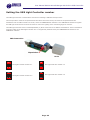
1
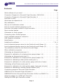
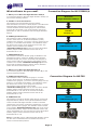
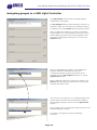
SIMKITS
SIMULATOR PARTS
User Manual
Simkits Aircraft Gauge
with built-in
USB Controller
Calibration
&
Connecting to Flight Simulator X
and Flight Simulator 2002/4
Release 30 March 2007
Copyright 2007
TRC Development b.v.
Stationsweg 39
4241 XH ARKEL
THE NETHERLANDS
Phone +31 183 562 522 - Fax +31 183 564 268
email: [email protected]
SIMKITS
User Manual Simkits Aircraft Gauge with built-in USB Controller
SIMULATOR PARTS
Contents
Page
What software do you need . . . . . . . . . . . . . . . . . . . . . . . . . . . . . . . . . . . . . 3
Connection Diagram for Microsoft Flight Simulator 2002/2004 . . . . . . . . . . . . . . 3
Connection Diagram for Microsoft Flight Simulator X . . . . . . . . . . . . . . . . . . . . 3
How does it work . . . . . . . . . . . . . . . . . . . . . . . . . . . . . . . . . . . . . . . . . . . . 4
What does the dipswitch do . . . . . . . . . . . . . . . . . . . . . . . . . . . . . . . . . . . . . 4
Why calibration . . . . . . . . . . . . . . . . . . . . . . . . . . . . . . . . . . . . . . . . . . . . . . 4
Why up to 8 calibration values . . . . . . . . . . . . . . . . . . . . . . . . . . . . . . . . . . . 4
How to connect multiple gauges to my PC . . . . . . . . . . . . . . . . . . . . . . . . . . . 4
How does the gauge connect to flight simulator. . . . . . . . . . . . . . . . . . . . . . . . 4
More complex gauges . . . . . . . . . . . . . . . . . . . . . . . . . . . . . . . . . . . . . . . . . 5
Calibration for other gauges . . . . . . . . . . . . . . . . . . . . . . . . . . . . . . . . . . . . . 5
Connecting other Simkits gauges. . . . . . . . . . . . . . . . . . . . . . . . . . . . . . . . . . 5
List of available gauges to connect to. . . . . . . . . . . . . . . . . . . . . . . . . . . . . . . 5
USB Dipswitch examples . . . . . . . . . . . . . . . . . . . . . . . . . . . . . . . . . . . . . . . 6
Identification . . . . . . . . . . . . . . . . . . . . . . . . . . . . . . . . . . . . . . . . . . . . . . . 6
Installing the software . . . . . . . . . . . . . . . . . . . . . . . . . . . . . . . . . . . . . 7, 8, 9
List of supported gauge values for the Simkits Aircraft Gauge (1). . . . . . . . . . . 10
List of supported gauge values for the Simkits Aircraft Gauge (2). . . . . . . . . . . 11
The calibration screen for the Simkits Aircraft Gauge . . . . . . . . . . . . . . . . . . . 12
Other calibration programs . . . . . . . . . . . . . . . . . . . . . . . . . . . . . . . . . . . . . 12
Calibrating an Airspeed scale (part 1). . . . . . . . . . . . . . . . . . . . . . . . . . . . . . 13
Example for calibration of a single pointer gauge (steps 1-4) . . . . . . . . . . . . . . 13
Calibrating an Airspeed scale (part 2). . . . . . . . . . . . . . . . . . . . . . . . . . . . . . 14
Example for calibration of a single pointer gauge (steps 4-8) . . . . . . . . . . . . . . 14
Example for calibrating a dual pointer scale (part 1). . . . . . . . . . . . . . . . . . . . 15
Example for calibration of a dual pointer gauge (left side of scale) . . . . . . . . . . 15
Calibrating a Dual Pointer scale (part 2) . . . . . . . . . . . . . . . . . . . . . . . . . . . . 16
Example for calibration of a dual pointer gauge (right side of scale) . . . . . . . . . 16
Example for calibrating a Vertical Speed Indicator (VSI) . . . . . . . . . . . . . . . . . 17
Connecting gauges to Microsoft Flight Simulator . . . . . . . . . . . . . . . . . . . . . . 18
USBFSXLink for Microsoft Flight Simulator X . . . . . . . . . . . . . . . . . . . . . . . . . 18
USBFSUIPCLink for Microsoft Flight Simulator 2002/4 via FSUIPC 3.x . . . . . . . . 18
Assigning gauges to a USB Light Controller . . . . . . . . . . . . . . . . . . . . . . . . . . 19
Setting the USB Light Controller number . . . . . . . . . . . . . . . . . . . . . . . . . . . 20
Page 2
SIMKITS
User Manual Simkits Aircraft Gauge with built-in USB Controller
SIMULATOR PARTS
Connection Diagram for MS FS2002/4
What software do you need?
1. When you run Microsoft Flight Simulator 2002/4
To connect the gauges to Microsoft Flight Simulator 2002/4 you
will need the following software:
Microsoft
Flight Simulator 2002/4
A. FSUIPC 3.x from Pete Dowson
This software can be downloaded from the website
www.simmarket.com and is so-called payware. Since Microsoft
Flight Simulator 2002/4 does not has an open interface to
connect hardware like the Simkits gauges to, Pete Dowson,
from the UK, has written a very good interface, opening all
parameters for add-on hardware to Microsoft Flight Simulator
2002/4.
FSUIPC
version 3.x
B. USBGaugecalibration.exe
This software is used to calibrate the gauge to a certain
function. Since there are 74 different faceplates (scales)
included in the gauge kit, you need to “tell” the gauge how the
pointer(s) on the scale should behave. The calibration values
are saved in the memory of the gauge microcontroller. This
software comes included in the installer
“SimkitsAircraftGauge.zip”and can be found at the Simkits
website, Support section/ Software section and can be
downloaded at no cost.
Simkits
USBFSUIPCLink.exe
C. USBFSUIPCLink.exe
This software connects the Simkits gauge to FSUIPC3.x and
translates the values “read” from FSUIPC (Microsoft Flight
Simulator 2002/4) into pointer movements, following the onscreen pointer positions of the gauges. This software comes
included in the installer “SimkitsAircraftGauge.zip”and can
be found at the Simkits website, Support section/ Software
section and can be downloaded at no cost.
1. When you run Microsoft Flight Simulator X
To connect the gauges to Microsoft Flight Simulator X you will
need the following software:
A. USBGaugecalibration.exe
This software is used to calibrate the gauge to a certain
function. Since there are 74 different faceplates (scales)
included in the gauge kit, you need to “tell” the gauge how the
pointer(s) on the scale should behave. The calibration values
are saved in the memory of the gauge microcontroller.
This software comes included in the installer
“SimkitsAircraftGauge.zip” and can be found at the Simkits
website, Support section/ Software section and can be
downloaded at no cost. and can be found at the Simkits
website, Support section/ Software section and can be
downloaded at no cost.
Connection Diagram for MS FSX
B. USBFSXLink.exe
This software connects the Simkits gauge directly to Microsoft
Flight Simulator X (Deluxe version) and translates the values
“read” from Microsoft Flight Simulator X’s built-in interface
(SimConnect) into pointer movements, following the on-screen
pointer positions of the gauges. This software comes included
in the installer “SimkitsAircraftGauge.zip” and can be found
at the Simkits website, Support section/ Software section and
can be downloaded at no cost. and can be found at the Simkits
website, Support section/ Software section and can be
downloaded at no cost.
Note: the standard version of Microsoft Flight Simulator X does
not offer the so-called SimConnect interface and cannot be
used to connect Simkits products.
Page 3
Microsoft
Flight Simulator X
(Deluxe version)
Simkits
USBFSUIPCLink.exe
SIMKITS
User Manual Simkits Aircraft Gauge with built-in USB Controller
SIMULATOR PARTS
How does it work?
The Simkits USB driven Aircraft Gauge is a so-called “standalone” product. This means that the product is complete
(except for one or two servos) to be controlled directly from
your PC running Microsoft Flight Simulator (2002, 2004 or
FSX) using Simkits interface software (to be downloaded
from the Simkits Support section on the internet at
www.simkits.com). When you want to connect the gauge
to Microsoft Flightsimulator 2002/4 you will need also the
third party software FSUIPC3, to be downloaded from the
website www.simmarket.com. To find it quickly, enter
“FSUIPC” in the search field on the simmarket website.
When you use Microsoft Flightsimulator X, you do not need
any other software than from Simkits, which can be
downloaded from the support section of the Simkits website
at www.simkits.com.
The product contains its own Microcontroller on the small
PCB. This Microcontroller contains software which is able to
control one or two servos and the lighting.
The Microcontroller PCB also contains a small memory chip,
which holds the calibration values (even if power is
disconnected).
What does the dip switch do?
Since you can connect up to 64 of the same type of this
Simkits Aircraft Gauge to your PC (which are all the same
product technically, only the faceplate differs) there must
be a way to distinguish one gauge from another.
Therefore Simkits has designed the gauge in such a way,
that you can alter the “identity” of the gauge by setting a
so-called dip switch.
The identity is “TRC GAUGE” with a 2 digit number added,
like TRC GAUGE 00, TRC GAUGE 01, TRC GAUGE 02, etc.
Please note that “00” is a valid number for a computer.
Using the dip switches, you can create a unique identity for
each gauge and number them from 00 to 63, creating 64
different identities.
The settings of the dip switch create a binary value.
Although the switches are physically numbered from 1 to 6,
their values for the setting is binary as follows:
1=1
4= 8
2=2
5 = 16
3=4
6 = 32
By using a combination of these 6 switches, you can create
any value between 0 and 63 (included). Simply “add” the
value of each switch set together. More about the
dipswitches and examples can be found on the next page.
Why calibration
As every scale on a gauge is different, the software “needs
to know” how the scale looks like. There are many
possibilities: a single pointer, a dual pointer (bot either with
their axis in the center or at the sides of the gauge) a
gauge with a pointer which center lies at the lower part of
the scale, etc.
As there are 74 different faceplates included (a combination
of faceplates for smaller and larger gauges), you can see
that each faceplate has its typical division of the scale.
Some scales are linear. This means that the distances
between the values are equally divided over the whole
scale. Some other scales are non-linear. This means that at
a certain area of the scale the distances between the values
(stripes) is equal, but when one goes up or down the scale,
the distances become smaller or larger.
An airspeed indicator is a typical example.
Therefore (only once) after you have completed the
construction of the gauge to the type you have choosen,
you need to calibrate the scale and save these values in the
memory of the gauge Microcontroller.
Why up to 8 calibration values?
The software which drives the servo can calculate the exact
position of the pointers when a scale is linear. This means
that when you have a gauge scale which indications run for
example from 0 to 100 over the full scale and where the
distances of the stripes are equal over the full scale, you
would only have to enter 2 values: 0 and 100 and calibrate
only these 2 positions. In that case, just enter an X into the
value entry fields which you do not use. The Simkits Aircraft
Gauge calibrations offers up to 8 entry fields for scale
values so that even complex non-linear scales can be
calibrated. We advise to use as much values as possible,
even on a linear scale.
When you have built the gauge using only one pointer,
please enter an X in the pointer field for pointer 2.
How to connect multiple gauges to my PC?
The Simkits Aircraft Gauge is powered via the USB
connection. The servos inside the gauge do consume a
maximum of approx. 400 mA. in total. Under normal
circumstances the standard USB port of your PC can handle
the necessary power for this gauge (the official output for
each USB conenctor on your PC is 500mA). However, we
recommend to use a separate USB HUB with additional
power to connect the Simkist Aircraft Gauge to your PC.
More on separate HUBs can be found at the Simkits website
or from your local computer products supplier.
How does the gauge connect to Flight Simulator?
The gauge can connect to 3 different Microsoft Flight
Simulators: FS2002, FS2004 and FSX.
For Microsoft Flight Simulators: FS2002 and FS2004 you
will need FSUIPC from Pete Dowson (see “How does it
work”). This is because MS FS2002 and 2004 do not have
an interface to exchange parameters with the outside
world. Pete Downson has written a very good interface to
acces the internals of MS FS2002 and 2004.
Microsoft Flight Simulator X has such an interface,
developed by Microsoft, called SimConnect.
When you use FSX, you do not need any additional software
from third parties. The Simkits software allows you to
connect to Microsoft Flight Simulator directly, but only using
the Microsoft Flight Simulator X Deluxe edition.
Page 4
SIMKITS
User Manual Simkits Aircraft Gauge with built-in USB Controller
SIMULATOR PARTS
More complex gauges
Connecting other Simkits gauges than the
As the Simkits Aircraft Gauge with built-in USB Controller is
standard Simkits Aicrcraft Gauge to
the first out of a new series of gauges, also the more
complex gauges will be offered soon:
- the light control (a USB device which can control the
lighting in all new USB gauges)
- the Attitude Indicator and the Turn & Bank Indicator *)
- the ADF, Altimeter and Heading Indicator *)
- the VOR1 and VOR2 *)
- the TRC472 Switches *)
Microsoft Flight Simulator
During the release of more complex gauges, also new
versions of the connection software USBFSXLink.exe and
USBFSUIPCLink.exe will be released, which are able to
connect these more complicated gauges to Microsoft Flight
Simulator 2002/4 or Microsoft Flight Simulator X (Deluxe
version).
- the Trimwheel *)
- the Flaps Switch *)
List of available gauges to connect to
- the Gear Switch
As internally in Microsoft Flight Simulator there is in
- the Tank Switch
principle only 1 Airspeed Indicator, 1 Vertical Speed
- the Keylock Starter Switch *)
Indicator and so on, you choose the number for the gauge
- the Yoke system
pointer you like to calibrate from the list on this page.
- Throttle, Prop and Mixture (Cessna style)
This value is entered in the B or C field of the calibration
- Dual Throttle Quadrant (Dual Engine, Beechcraft style)
window (see page 12) and will show the choosen gauge
- Warning Panel
type in the field immediately beneath.
- Tank Switch
There are also gauges which exist as a first, second, third
and many more, all in random order.
and even fourth gauge, like for example a Tachometer
(RPM). For each engine there is a separate Tachometer.
*) These products also have dip switches to create more
Depending on the number of engines your choosen aircraft
than a single product in a setup (for example 2 trim
has, you choose the possible Tachometer or other Engine
wheels can be set as one vertical trim and one horizontal
instruments from the list.
trim, one can have an altimeter left and one right in the
When you choose to simulate a single engine aircraft,
panel, etc.
always choose the lowest numbered gauge (for example
Tachometer Engine 1).
And of course, if you have already a CCU, you can use the
existing CCU and expand using the USB gauges! They will
not conflict with eachother.
See page 10 and 11 for the list of
supported gauges and assignments.
Calibration for other Simkits gauges
Some of the more complex Simkits USB gauges (like an
Altimeter, Heading Indicator, Attitude Indicator, Turn &
Bank Indicator, etc.) cannot be calibrated using the
“standard” calibration software. Therefore calibration for
other gauges than the Simkits Aircraft Gauge is
accomplished by separate graphical enhanced calibration
software. Note: at the time this manual becomes available
it might be that the more complex SImkits gauges are not
yet available as USB driven gauges with their own
microprocessor inside. Please check the Simkits website
www.simkits.com.
Page 5
SIMKITS
User Manual Simkits Aircraft Gauge with built-in USB Controller
SIMULATOR PARTS
USB Dip Switch examples
USB Controller
Lamp connection
USB connection
This is a so-called digital table. By setting a certain dip switch
combination, the USB Controller can be given a number. For
example, setting dip switch 2, 3 and 4 to on, gives the USB
Controller the value 15 (TRC GAUGE 16). Gauges can be
numbered from 0 to 63 offering 64 different identities.
Dip switches
Servo 1 Connector
There are 6 dip switches, numbered from 1 to 6. Each dip
switch has it’s own value, as below:
1=1
4= 8
2=2
5 = 16
3=4
6 = 32
Servo 2 Connector
Identification
You can have up to 64 Simkits Aircraft Gauges (the type with one or two pointers) with built-in USB Controller connected to
your computer, plus mostly 2 of each more complex navigation gauges like Altimeter, Attitude Indicator, Turn & Bank
Indicator, Heading Indicator, VOR1, VOR2 and ADF.
Since most computers have only a few USB ports, you need to use a so-called USB HUB with additional power supply (7-port
HUBS are available from the Simkits Website or at any computer store) to control and power up the gauge.
The gauge identifies itself as a so-called HID device towards Windows (XP or Vista is recommended). This means that you do
not need a separate USB driver for this device. The SImkits Aircraft Gauge is recognized by Windows at first connection.
The “name” of the device in Windows is “TRC GAUGE 00” up to “TRC GAUGE 63”, depending on the setting of the dip
switches. The HID device can be found in the Windows system ‘Human Interface Devices” and each gauge is displayed as
‘USB-HID”.
The settings of the dip switch is read out by the on-board microprocessor of the USB controller and the HID recognizable
name is dynamically generated and forwarded over the USB conenction to the PC. Changing the dip switch while the
controller is connected to the PC (not recommended!) does not change the identification! The USB controller has to be
disconnected and connected again to your PC in order to bring the new dip switch setting in action and for your PC to
recognize the gauge with the new numbering.
Page 6
SIMKITS
User Manual Simkits Aircraft Gauge with built-in USB Controller
SIMULATOR PARTS
Installing the software
5.
First download the file SimkitsAircraftGaugesetup.zip, which
you can find at www.simkits.com/software.php. When you
have unzipped the file in a directory, you will see 2 files:
setup.exe and SimkitsUSB.msi (the installer). Now start
“setup.exe” by double clicking on the file icon or file name.
1.
If this is the first time you download software which uses
the so-called “Microsoft dot.net” (.net) environment, you
will see the next screen (2). If you do not see this screen,
but instead you see the screen number 12, continue
reading as from screen number 12. You obviously have the
“dot.net” system files already on your PC installed.
2.
Follow the directions as given in screen 5.
6.
Follow the
steps as
given in
the
screens 6,
7 and 8.
7.
To install the .NET framework, you should be conencted to
the internet prior to continue now. If you are not connected
to the internet, please do so now. When you have clicked
“Yes” on the window in picture 2, you computer will
connect to the Microsoft internet site where you can
download the necessary .NET system files.
3.
8.
Now choose on
the web page
“Download X86
version” .
This presents
screen no. 3,
where you press
“Run”.
4.
Page 7
SIMKITS
User Manual Simkits Aircraft Gauge with built-in USB Controller
SIMULATOR PARTS
When the download is finished, screen No. 9 will be shown.
This screens asks you to close the internet explorer used to
download and the .NET files.
Installation of the software necessary to drive the Simkits
USB Aircraft Gauges from SM FS2004 of from FS-X.
Now follow the directions as given in screen 12 to continue
installation of the software.
9.
12.
When you have closed the Internet Explorer, the
installation of the .NET files will start as shown in picture
No. 10.
10.
Screen 13 asks you to install the files in a certain folder. If
you are satisfied with the proposed folder, press “Next”.
13.
When you screen No. 11 the installation of the Microsoft
.NET environment is completed.
Screen 12 shows the continuation of the actual Simkits
USB Aircraft Gauge software, needed to control the Simkits
USB Aircraft Gauge.
11.
Page 8
SIMKITS
User Manual Simkits Aircraft Gauge with built-in USB Controller
SIMULATOR PARTS
Screen 14 asks to re-confirm the choosen installation
folder. Press “Next” to continue.
When all software is installed, screen 16 shows. You are
now ready to start using the Simkits USB Aircraft Gauge
software.
14.
16.
Screen 15 shows the progress during installation of the
Simkits USB Aircraft Gauge calibration and control
software.
To start any of the Simkits USB Aircraft Gauge software, go
to “Start”on your PC, choose “All Programs” and Look for
the installed software “Simkits USB”. There are 5 submenus. Each menu let you choose for one of the Simkits
USB Aircraft Gauge programs:
15.
USBFSUIPCLink
The software to run (in combination with FSUIPC 3.x) with
Microsoft Flightsimulator 2002/2004.
USBFSUIPCLink (autostart)
The software to run (in combination with FSUIPC 3.x) with
Microsoft Flightsimulator 2002/2004. Can be used when
you want to use automatic starting for all software.
USBFSXLink
The software to run with Microsoft Flightsimulator X.
USBFSXLink (autostart)
The software to run with Microsoft Flightsimulator X. Can
be used when you want to use automatic starting for all
software.
USBGaugecalibration
The software to calibrate a newly assembled gauge. This is
the first software to use, prior to any other software!
17.
Page 9
SIMKITS
User Manual Simkits Aircraft Gauge with built-in USB Controller
SIMULATOR PARTS
List of supported gauge values for the Simkits Aircraft Gauge (1)
See explanation on the use of the above values on the next page.
Gauge
FS2004
FSX
Function
Yes
Yes
No
No
903
906
Project Magenta
Project Magenta / VSI
Yes
Yes
No
No
No
No
905
904
Project Magenta/ Not tested
Project Magenta/ Not tested
Project Magenta / Not
Yes
No
910/907
Project Magenta / Not
Yes
Yes
Yes
No
Yes
No
901-902
9
909
Project Magenta
In percent of full position
Project Magenta / Not
Yes
Yes
Yes
Yes
Yes
Yes
Yes
Yes
Yes
Yes
Yes
Yes
Yes
Yes
Yes
Yes
Yes
Yes
Yes
Yes
Yes
Yes
Yes
No/Yes
Yes
Yes
Yes
Yes
Yes
Yes
Yes
Yes
Yes
Yes
Yes
Yes
2
1
102-103
503
112
117/115
90-113
110
91-92
Cessna 172 Airspeed Indicator
Cessna 172 EGT/Fuel Flow Indicator
Cessna 172 Fuel Indicator Left/Right
Cessna 172 Oil Temp. & Oil Press Gauge
Cessna 172 Suction Gauge/Ammeter
Cessna 172 Tachometer Cessna 172
Cessna 172/182 Vertical Speed Indicator
Cessna 182 Airspeed Indicator
Cessna Caravan Airspeed Indic.
Cessna Caravan Vert. Speed Indic.
Cessna Tachometer Cessna 182
Yes
Yes
Yes
Yes
yes
Yes
Yes
Yes
Yes
Yes
Yes
Yes
Yes
Yes
Yes
Yes
Yes
Yes
Yes
Yes
Yes
Yes
1
104/107-108
501-502
102-103
6/80
109
2
1
1
2
109
Cirrus R-20/22 EGT/CHT
Cirrus R-20/22 Man. Pr./Fuel Fl.
Cirrus R-20/22 Volt/AMP
Cirrus SR-20/22 Oil Temp/Press
Cirrus SR-20/22 RPM
Yes
Yes
yes
Yes
Yes
Yes
Yes
Yes
Yes
Yes
104-105
106/107-108
81/80
102-202
109
Corsair Airspeed Indicator Voight Corsair
Corsair Manifold Pressure - Vaught Corsair
Corsair Vertical Speed Indicator Voight Corsair
Yes
Yes
Yes
Yes
Yes
Yes
1
106
2
Extra 300 Airspeed Indicator Extra 300S
Yes
Yes
1
F16 Airspeed Indicator F16
F16 Cabin Press ALT
F16 EPU FUEL
F16 FTIT
F16 Fuel
F16 Hyd
F16 NOZ POS
F16 Oil
F16 RPM
Yes
No
No
No
Yes
No
No
No
Yes
Yes
No
No
No
Yes
No
No
No
yes
1
737 APU for Overhead Panel
737 Cabin Climb
calibration/Not tested
737 Cabin Temp Ctrl. C
737 Cabin Temp. Ctrl F
737 Crew Oxygen
implemented
737 Diff Pressure ALT Cabin Gauge
tested
737 Duct Pressure L-R
737 Flaps Gauge
737 Fuel Temp C
tested
Baron Airspeed Indicator
Baron Fuel Flow
Baron Fuel Gauge Beechcraft Baron
Baron Instrument Air
Baron Manifold Press Beech Baron
Baron Oil Temp/Pressure Beech Baron
Baron Tachometer Beechcraft Baron
Baron Temp CHT EGT
Baron Vertical Speed Indicator
Bell 206B Vertical Speed Indicator
Bell Airspeed Indicator
Bell Engine Oil Gauge
Bell Fuel Quantity Gauge
Bell Gas Producer
Bell Load Fuel Gauge
Bell Rotor Power Torque Gauge
Bell Torque Percent Gauge
Bell XMSN Oil Gauge
1
107-108/207-208
501-502
6
106-206
102-202/103-203
109-209
104-105/204-205
2
503
Note
Pph or Gph
suction pressure / inHg
Pph or Gph
Fuel center ?
Quantity ?
112
See explanation on the use of the above values on the next page.
Page 10
SIMKITS
User Manual Simkits Aircraft Gauge with built-in USB Controller
SIMULATOR PARTS
List of supported gauge values for the Simkits Aircraft Gauge (2)
Gauge
FS2004
General Airspeed Indicator . . . . . . . . . . . . . . . . . Yes
General Vertical Speed Indicator . . . . . . . . . . . . . Yes
General Pitch Indicator . . . . . . . . . . . . . . . . . . . . Yes
General Bank Indicator . . . . . . . . . . . . . . . . . . . . Yes
General Radio Altitude Indicator . . . . . . . . . . . . . Yes
General Instrument Air Dual Engine . . . . . . . . . . Yes
General inclinometer . . . . . . . . . . . . . . . . . . . . . . No
General turn coord . . . . . . . . . . . . . . . . . . . . . . . . No
General Flaps Position Indicator . . . . . . . . . . . . . Yes
General Engine 1 Oil Qty. . . . . . . . . . . . . . . . . . . Yes
General Engine 1 Oil Temp . . . . . . . . . . . . . . . . . Yes
General Engine 1 Oil Press . . . . . . . . . . . . . . . . . Yes
General Engine 1 EGT . . . . . . . . . . . . . . . . . . . . Yes
General Engine 1 CHT . . . . . . . . . . . . . . . . . . . . Yes
General Engine 1 Manifold Pressure. . . . . . . . . . Yes
General Engine 1 Fuel Flow (GPH) . . . . . . . . . . . Yes
General Engine 1 Fuel Flow (PPH) . . . . . . . . . . . Yes
General Engine 1 Prop RPM . . . . . . . . . . . . . . . . Yes
General Engine 1 Torque . . . . . . . . . . . . . . . . . . . Yes
General Turbine 1 ITT . . . . . . . . . . . . . . . . . . . . . Yes
General Turbine 1 N1 . . . . . . . . . . . . . . . . . . . . . Yes
General Turbine 1 N2 . . . . . . . . . . . . . . . . . . . . . Yes
General Turbine 1 Temp Out . . . . . . . . . . . . . . . . Yes
General Engine 1 Fuel Press. . . . . . . . . . . . . . . . Yes
for FSX . . . . . . . . . . . . . . . . . . . . . . . . . . . . . . . . . .
General Engine 1 N1 . . . . . . . . . . . . . . . . . . . . . . Yes
General Engine 2 Oil Qty. . . . . . . . . . . . . . . . . . . Yes
General Engine 2 Oil Press . . . . . . . . . . . . . . . . . Yes
General Engine 2 Oil Temp . . . . . . . . . . . . . . . . . Yes
General Engine 2 EGT . . . . . . . . . . . . . . . . . . . . Yes
General Engine 2 CHT . . . . . . . . . . . . . . . . . . . . Yes
General Engine 2 Manifold Pressure. . . . . . . . . . Yes
General Engine 2 Fuel Flow (GPH) . . . . . . . . . . . Yes
General Engine 2 Fuel Flow (PPH) . . . . . . . . . . . Yes
General Engine 2 Prop RPM . . . . . . . . . . . . . . . . Yes
General Engine 2 Torque . . . . . . . . . . . . . . . . . . . Yes
General Turbine 2 ITT . . . . . . . . . . . . . . . . . . . . . Yes
General Turbine 2 N1 . . . . . . . . . . . . . . . . . . . . . Yes
General Turbine 2 N2 . . . . . . . . . . . . . . . . . . . . . Yes
General Turbine 2 Temp Out . . . . . . . . . . . . . . . . Yes
........................................
Mooney Airspeed Indicator . . . . . . . . . . . . . . . . . Yes
........................................
Robinson Airspeed Indicator R44 . . . . . . . . . . . . Yes
Robinson Carburator Heat R22 . . . . . . . . . . . . . . Yes
Robinson R22/R44 Engine Rotor RPM Gauge . . Yes
Robinson R22/R44 Manifold Pressure Gauge. . . Yes
........................................
Schweizer Airspeed Indic. Schweizer Sailplane . Yes
........................................
Sopwith Airspeed Indicator Sopwith Camel . . . . . Yes
Sopwith Tachometer Sopwith Camel . . . . . . . . . . Yes
FSX
Function
Yes
Yes
Yes
Yes
Yes
Yes
No
No
Yes
Yes
Yes
Yes
Yes
Yes
Yes
Yes
Yes
Yes
Yes
Yes
Yes
Yes
Yes
Yes
1
2
3
4
5
6
7
8
9
101
102
103
104
105
106
107
108
109
110
111
112
113
114
115
Yes
Yes
Yes
Yes
Yes
Yes
Yes
Yes
Yes
Yes
Yes
Yes
Yes
Yes
Yes
116
201
202
203
204
205
206
207
208
209
201
211
212
213
214
Yes
1
Yes
Yes
Yes
Yes
1
118
90-116
106
Yes
1
Yes
Yes
1
109
Note
Not tested - future use
Not tested - future use
Limited at 2000'
Future use
Future use
Used for Bell 206/Soft corr.
Used for Robinson R22/44
Function numbers:
The number in the column Function has to be entered into the entry window (see next page) of the calibration software
named “Pointer 1” or “Pointer 2” to assign the gauge to a certain gauge function.
Important note:
The colums FS2004, FSX and Note have some remarks about the function of the gauge and if it is supported in the different
environments.
As the software for the USB Aircraft Gauge is developed continously and new versions are released regularly, eventual nonsupported functions will be added in the near future.
All feedback on functionality is welcome. Whenever you discover a “bug” in the software, please send an email to
support@simkits to let us know.
Page 11
SIMKITS
User Manual Simkits Aircraft Gauge with built-in USB Controller
SIMULATOR PARTS
The calibration screen for the Simkits Aircraft Gauge
A
C
B
E
D
F
The screen for the calibration of the “Simkits Aircraft Gauge”
A = Pull Down Menu available gauges (it only recognizes the so-called “Simkits Aircraft Gauges”)
B = Enter here the value (type of gauge) for the connection of pointer 1
C = Enter here the value (type of gauge) for the connection of pointer 2 (when available in hardware, otherwise insert the
character X).
D = Enter here the values of the calibration points on the scale. 8 values can be entered. In case there are less than 8 values
available, please enter the character X in the remaining fields. In case of more values, use values strategically spread
over the whole scale.
E = Slider to adjust the pointer position to the calibration position (1, 2, 3 etc.). Either move the slider with your mouse or
click on the left or right side for fine tuning. The slider can cause the pointer to move clockwise or anti-clockwise when
you move the slider to the left, depending on which version of the software you have. This has no influence in the
calibration.
F = When finished, save the values in the gauge memory by pressing “Save Calibration”. Now you can close the program.
Other calibration programs
There are different calibration programs available for different kind of Simkits Gauges. The so-called “Simkits Aircraft Gauge”
(which can have many different identities) uses the program USBGaugecalibration.exe. This program can calibrate these type
of gauge for all kinds of scales/faceplates because it controls the calibration for 1 or 2 pointers only.
For other, more complex gauges, calibration software with a graphical interface is available. Each type of gauge has its own
calibration software with graphical interface.
Page 12
SIMKITS
User Manual Simkits Aircraft Gauge with built-in USB Controller
SIMULATOR PARTS
Calibrating an Airspeed scale (part 1)
TRC GAUGE 00
Example for calibration of a single pointer gauge (steps 1-4)
Only use the left side of the calibration screen. Select the gauge number in the pull
down menu to select the physical gauge to calibrate.
Enter the type of gauge to calibrate in the field under “Pointer 1” from the list of
possible gauges.
Enter up to 8 values from the scale of the faceplate in the fields above the sliders.
When there are less than 8 values to enter, just put X in the empty field. When there
are more than 8 values on the scale, jump over values which have a linear scale (like
from 60 to 100 in the example).
Now use the sliders (step 1 to step 8) to position the pointer on the value entered in
the field for each step. (Moving the slider to left or right may move the pointer
clockwise or anti-clockwise or vice-versa. This has no influence on the calibration, as
long as the position of the pointer for each step is to the value you entered in that
field. When satisfied, finish by clicking “Save Calibration”. This saves the calibration
values in the gauge memory.
NOTE: when the pointer does not move during calibration, it could very well
be that you have connected the servo for the first (and only) pointer to the
second servo control connector. In that case use the right column of the
calibration screen instead and enter X in the pointer 1 field.
Page 13
SIMKITS
User Manual Simkits Aircraft Gauge with built-in USB Controller
SIMULATOR PARTS
Calibrating an Airspeed scale (part 2)
TRC GAUGE 00
1
Example for calibration of a single pointer gauge (steps 4-8)
Page 14
SIMKITS
User Manual Simkits Aircraft Gauge with built-in USB Controller
SIMULATOR PARTS
Calibrating a dual pointer scale (part 1)
103
102
Example for calibration of a dual pointer gauge
(left side of scale)
Select the gauge number in the pull down menu to select the physical gauge to
calibrate.
Enter the type of gauge pointer to calibrate in the field under “Pointer 1” from the list
of possible gauges. Enter the second type of gauge pointer to calibrate in the field
under “Pointer 2” from the list of possible gauges. (It might very well be that
during the construction of the gauge the servo wiring has been mixed. This is
no problem, but it could mean that you have to use the right column to
calibrate the left pointer and vice versa).
Enter up to 8 values from the scale of the faceplate in the fields above the sliders.
When there are less than 8 values to enter, just put X in the empty field. When there
are more than 8 values on the scale, jump over values which have a linear scale (like
from 60 to 100 in the example).
Now use the sliders (step 1 to step 8) to position the pointer on the value entered in
the field for each step.
When satisfied, finish by clicking “Save Calibration”. This saves the calibration values in
the gauge memory.
Page 15
SIMKITS
User Manual Simkits Aircraft Gauge with built-in USB Controller
SIMULATOR PARTS
Calibrating a dual pointer scale (part 2)
103
102
Example for calibration of a dual pointer gauge
(right side of scale)
Page 16
SIMKITS
User Manual Simkits Aircraft Gauge with built-in USB Controller
SIMULATOR PARTS
Calibrating a Vertical Speed Indicator
Example for calibration of a Vertical Speed Indicator
The VSI has to be treated with special attention. As most VSI scales have very low
values printed (but mostly in the scale the text “100 feet per min is printed”), the
values entered in the calibration windows also need to be entered properly. Start with
negative values in feet per minute and up to positive values. Now use the sliders (step
1 to step 7) to position the pointer on the value (x 10) as entered in the field for each
step. Since we have only 8 fields to enter data in and the scale offers 9 positions, we
can omit to enter the 500 feet (negative and positive) values, since the scale is fully
linear. We therefore use only 7 entries.
When satisfied, finish by clicking “Save Calibration”. This saves the calibration values in
the gauge memory. It may be that the values shown are changed slightly when saved.
Page 17
SIMKITS
User Manual Simkits Aircraft Gauge with built-in USB Controller
SIMULATOR PARTS
Connecting gauges to Microsoft Flight Simulator
There are 2 different programs supplied to connect your USB gauge to Microsoft Flight Simulator. Although their “looks and
feels” are the same, they are for different versions of Microsoft Flight Simulator. Please only use one program!
USBFSXLink.exe
This is the program to connect the gauges to Microsoft Flight Simulator X (Deluxe version only). FSUIPC is not needed here.
USBFSUIPCLink.exe
This is the program to connect the gauges to Microsoft Flight Simulator 2002 and 2004 and FSUIPC 3.x must be used.
The USBxxLink screen for connecting gauges to Microsoft Flight Simulator is very easy to use. At startup the software “looks”
which Simkits USB devices are connected to your PC and displays the number d function (you must have calibrated the
gauges prior to use, otherwise an error will occur).
Pressing the button “Connect to Flight Simulator” will connect the gauges to FS2002/4 or FSX. Flight Simulator must be
running prior to pressing this button! When - after starting the Flight Simulator software you cannot “see” this program,
press and hold the ALT key, while pressing the TAB key untill this program appears again.
The window namend “Connected Gauges” shows 3 columns. The first column is the gauge name/number as recognized by
Windows. The second column shows the function(s) of the gauge and the 3rd column shows which light regulation will control
the lighting of the specific gauge.
The USB Light Control (separately available) let you control the lighting of gauges very easily “on the fly”. A maximum of 4
USB Light Controls can exist within a single PC/Flightsim setup. You can assign each gauge to a certain USB Light Control
enabling 4 groups of different lighting.
The XXLink software reads out the setting of the USB Light Control and sets the lighting of the gauge accordingly.
When you don’t have a USB Light Control, you can set the light manually in the XXLink software via the pull down menu
“Light Setting”, which also gives acces to the light assigment when using USB Light Control(s).
Page 18
SIMKITS
User Manual Simkits Aircraft Gauge with built-in USB Controller
SIMULATOR PARTS
Assigning gauges to a USB Light Controller
The Light Setting window shows the possible lighting
assignments for the gauges.
The Not Assigned window shows all gauges which are not
assigned or which are controlled by the software setting of
the lighting in the small Gal Set (General Lighting) window.
When no USB Light Controller is connected, the windows
“Light Regulator 1” to “Light Regulator 4” are grey colored
and the lighting intensity for all connected gauges can be
controlled by changing the setting (from 0 to 100) in the
Gal Set window.
When the USBFSUIPCLink software or the USBFSXLink
software recognizes a USB Light Controller, the
corresponding window will open and a gauge can be
“dragged” from the Not Assigned window to an opened
Light Control window.
When a USB Light Controller is found by the software, the
Gal Set (General Lighting) window will turn to grey and is
switched off for light control.
Just move the mouse pointer to a not assigned gauge, click
with the left mouse button and hold the button pushed in
while dragging the gauge name to an open Light Control
window.
Now the gauge can be controlled by turning the knob on the
assigned USB Light Controller.
(see also the next pages for using the USB Light
Controller).
Page 19
SIMKITS
User Manual Simkits Aircraft Gauge with built-in USB Controller
SIMULATOR PARTS
Setting the USB Light Controller number
The USB Light Controller is a stand-alone instrument containing a dedicated microprocessor.
The microprocessor reads out the potentiometer and when the knob is turned, the values of the potentiometer are
transmitted over the USB connection to the PC, where the USBFSUIPCLink software or the USBFSXLink software recognizes
the USB Light Controller and receives the values to control the lighting of the connected gauges in real time.
The USB Light Controller has a so-called dipswitches (2) which can be set into 4 different combinations. These combinations
form the number of the USB Light Controller as it is recognized by windows and by the USBFSUIPCLink software or the
USBFSXLink software.
USB Connection
Dipswitches
Knob
ON
ON
The Light Controller number is 3
The Light Controller number is 1
1 2
1 2
ON
ON
The Light Controller number is 4
The Light Controller number is 2
1 2
1 2
Page 20