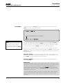
1
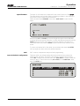
MT-REPORTER with B-200 Mixer with Mixing Desk User Manual V96/3.19 Businesspark Monrepos Monreposstraße 55 D-71634 Ludwigsburg Telefon: 07141/22660 Telefax: 07141/22667 2MBit: 07141/22380 Volksbank Heidenheim (BLZ 632 90110) Kto.-Nr.: 164 100 008 Swift Bank Code: DGZB DESG Handelsregister Ludwigsburg HRB 3695 1 Geschäftsführer: B. Burkhardtsmaier USt.-Id-Nr.: DE 146 187 117 Table of Contents MT-REPORTER with B-200 Mixer Appliance Documentation: Operation: Display Codes and Error Messages: Technical Informations: Assembly and Connections Terminals Terminals/EMC Measures 3 4 7 General Getting Started Main Menu Change ISDN Protocol Contrast Adjustment Connection Set-up Connection Set-up - Synch Display Closing Connection Data Input Data Input - Audio Data Data Input - G.722 Service Indicator Data Input - Dialing Data Input - Connection Information Connection Set-up Connection Set-up - Connection Established Closing Connection Auxiliary Functions Mixing Desk Numeric Keypad 8 9 10 10 10 11 12 13 14 15 16 17 19 19 21 22 23 24 25 Status and ISDN Messages Status and ISDN Messages - EURO System Reset Functions/Software Version 26 27 28 Setting of the Headroom Adjustment of the Codec Input Level 29 30 - All technical alteration are subject to change without further notice 2 Appliance Documentation MT-REPORTER with B-200 Mixer Introduction: ISO/MPEG 11172-3: G.722 / H.221: Introduction The Audio-ISDN appliance „ “ is designed for mobile live use. The unit is built into a PUR-FOAM case with impact-resistant frame, to avoid mechanical damage. All connectors and controls are recess-mounted. is compatible with ISO/MPEG 11172-3 and supports biThe directional Layer III. The result is 1 x 15 kHz audio bandwidth using 1 or 2 B-Channels. This complies with the highest possible audio quality in conjunction with data reduction and corresponds with the ITU recommendation for comment lines. Moreover the is compatible with the Philips 7 kHz telephone, supporting the standard G.722 and framing according to H.221. The can establish a connection to a PKI telephone and vice versa. As soon as the device recognises that no MPEG data are being transmitted at an incoming call, the G.722 standard is loaded automatically into the DSPs, thus also establishing compatibility with the PKI telephone. ISDN D-Channel protocols: Approx. 20 different D-Channel protocols are available for the allowing world-wide application. , The protocols 1TR6 and ETSI are already integrated before the device leaves the manufacturer. These can be selected via the supervisor menu. Master/Slave Structure: The fact that a connection via ISDN can be established fully automatically from just about anywhere in the world, irrespective of place, configuration or baud rate, is absolutely unique. The dialed appliance is always configured by the caller and transmission is ensured. 3 Appliance Documentation MT-REPORTER with B-200 Mixer Connections AUDIO IN/OUTPUT AUDIO INPUT MIC 1 and MIC 2: AUX INPUT: AUX OUTPUT: Headphone OUTPUT 1 and 2: Microphone input balanced; phantom power switchable (48Volt). Sensitivity: -32dBu .. -65dBu, adjustable Factory pre-set: approx. -54dBu Connector: XLR socket female Pin assignment: 1 GND 2 IN (+) 3 IN (-) Line Input balanced. Sensitivity: -12dBu .. +20dBu adjustable Factory pre-set: +6dBu Headroom 9dB Input impedance: approx. 10 kohms Connector: XLR socket female Pin assignment: 1 GND 2 IN (a) 3 IN (b) Line output balanced. Level max.: +21dBu (-10 .... +21dBu) Factory pre-set: +6dBu Headroom 9dB Connector: XLR socket male Pin assignment: 1 GND 2 OUT (+) 3 OUT (-) Headphones socket Level max. (Pot fully opened): +20dBu Connector: Mono jack socket Pin assignment: Tip: Ring: signal GND 4 Appliance Documentation MT-REPORTER with B-200 Mixer Connections HEADSET: Pin assignment: Pin 1: Pin 2: Pin 3: Pin 4: Pin 5: Pin 6: Pin 7: Pin 8: Connector: Connection norm EUROVISION Connection norm SRG HP1 - L HP1 - 0V GND MIC 1 + MIC 1 GND HP1 - 0V HP1 - R MIC 2 + MIC 2 GND HP2 - L HP2 - R HP2 - 0V TB - HP1 MIC 2 OFF Neutricon female, Type TI 8 DATA Interfaces: X.21: Serial, synchronous connection for transmission of the encoded audio data to external data communication equipment as well as for connection to a satellite modem. Baud rate: Connector: Pin assignment: 1 NC 2 Tx (a) 3 CTR (a) 4 Rx (a) 5 IND (a) 6 CLK (a) 7 NC 8 GND 9 Tx (b) 10 CTR (b) 11 Rx (b) 12 IND (b) 13 CLK (b) 14,15 NC ISDN: 32kBit/s to 320kBit/s 15-pin Sub-D connector Signal direction ref. to the Output Output Input Input Input Output Output Input Input Input Standardized connector to the ISDN network. Baud rate: 2 x B + D-Channel Connector: RJ45 Pin assignment: Pin 3 Pin 4 Pin 5 Pin 6 TXa TXc RXc RXa 5 Appliance Documentation MT-REPORTER with B-200 Mixer REMOTE CONTROL: Connections The switching informations at the inputs of the are transferred and made available at the remote station as Open-Collector signals. The inputs and outputs are isolated via optocouplers. Input wiring Imax: 10mA Output wiring Imax: 6mA Umax : 25V Additionally there is avaible one interface (RS232) for user data and serial Remote. REMOTE control (RS232): ANCILLARY DATA (RS232): serial, asynchronous interface for control of the Setting of the interface: 9600 baud 8 data bits 1 stop bit no parity Connector: 25-pole Sub-D connector by an external PC. serial, asynchronous interface for transmission of user data via the Setting of the interface: 1200 baud 8 data bits 1 stop bit no parity Connector: 25-pole Sub-D connector . 6 Appliance Documentation MT-REPORTER with B-200 Mixer REMOTE CONTROL: Connectors/EMC Measures Connector: 25-pin Sub-D connector Pin assignment: Pin Signal Empfohlene Funktion: 1 2 3 4 5 6 7 8 9 10 11 12 13 14 15 16 17 18 19 20 21 22 23 24 25 UTX STX GND IN8 GND IN7 IN6 IN5 IN4 IN3 IN2 IN1 IN GND SRX URX VCC OUT8 OUT7 OUT6 OUT5 OUT4 OUT3 OUT2 OUT1 OUT GND Userdata Transmit Seriell Remote Transmit Red-Light IN Reset (Index) FF Rew Stop Record Play Gemeinsame Masse für alle Eingänge Seriell Remote Transmit Userdata Recieve +5V Red-Light OUT Reset (Index) FF Rew Stop Record Play common ground for all outputs The different GND connections (5, 13, 25) are isolated from each other! Please note: EMC measures: The recommended functions of the inputs and outputs correspond with the assignment of different MusicTAXI users. This pin assignment should be used for problem-free remote control of the respective connected appliances during transmissions between different MusicTAXIs or ´s. Under consideration of the electromagnetic compatibility (EMC) the following factors should be observed as regards connections: Use shielded cables for all connections, e.g. the well-known cable EMT 2111 is approved for audio cables. The screens are to be soldered to the named GND potentials or at the control/ interface cables to the „collar“ of the connector case. Use the respective NEUTRIK male/female connector for the 3-pin XLR plug/ sockets as well. Also connect pin 4 (casing) with pin 1 in the plugs/sockets. 7 Operation MT-REPORTER with B-200 Mixer Introduction: General The audio connection is set up in several steps: • Set-up of the ISDN lines (B-Channels) • Measuring and compensation of the signal propagation times • Synchronizing of the X.21 interfaces • Data transfer between or MusicTAXI for setting the desired • mode of operation (Audio mode, sampling rate, etc.) • Start of the audio transmission In order to make using of the MT-REP B200 as simple as possible, all the information necessary for transmission is entered and stored before the connection set-up. The data do not get lost if the appliance is switched off, which means that data for every remote station only need be entered once. The connection set-up is restricted to dialing a remote station from the stored list. Everything else takes place automatically. Key functions: The operation of the takes place by means of menu control via the display and the keys UP, DOWN and ENTER. If these keys are pressed down permanently, the selected function is repeated until the key is released again. This is particularly advantageous when entering of abbreviated names. The desired function is selected from the displayed list with the UP and the DOWN keys. The selected function is indicated on the display in an inverted manner (i.e. light character font on dark background). Each time the UP key is pressed, the mark jumps up one line. Once the upper line is reached, the mark moves down to the bottom line the next time the key is pressed. In the same way, the mark moves downwards one line each time the DOWN key is pressed. The selected function is executed by pressing the ENTER key. The last display line serves to return to the previous menu and, depending on the function, for storing any input made. 8 Operation MT-REPORTER with B-200 Mixer Power-on procedure: Getting Started The power switch is located at the right side. The adapts automatically to mains voltages between 90 and 240 VAC. After the start-up sequence the appliance performs a self-test of its individual components. During this procedure the address of DIALOG4 appears on the display. Two seconds later the Layer III software is loaded into the memory registers of the digital signal processors (DSP). Each status of the DSP’s is indicated in the display: After the DSP’s are loaded with the current software, the version number of the hardware appears in the display: The first line shows the version number and the date of the system software (V3.19). The following lines show the version number of the ISDN controller (V1.53), the D-Channel protocol and the D-Channel country code. 49 = 1TR6 (Federal Republic of Germany) 45 = EURO ISDN This information remains visible for 2 seconds and can be „frozen“, when the ENTER key is kept pressed during the booting procedure. The version numbers now appear inverse, until ENTER is pressed once again. 9 Operation MT-REPORTER with B-200 Mixer Main menu: Main Menu The loading procedure is now completed and the to the main menu: switches back The unit is now ready to receive incoming calls or to establish a connection. Connection set-up: In order to transmit audio signals, select the item CONNECT in the main menu and press the ENTER key. Find the desired number in the displayed selection list and confirm with ENTER. The connection is now established and the provides information on the current processes in the display: The two B-Channels are displayed as dark squares. The squares are always in the line, corresponding with the status of the respective B-Channel at the ISDN connection set-up. The dialed ISDN number is shown in the bottom line. DISC: B-Channel not connected (disconnected). CALL: Channel request runs in ISDN (Call). CON: Channel is connected. SYNC: B-Channels are synchronized to one data channel, the individual squares change into a single rectangle. REJ: If it was not possible to establish the connections, (rejected), the reasons therefore are displayed separately for both B-channels. 10 Operation MT-REPORTER with B-200 Mixer Connection set-up An example: The different Error messages are explained in the chapter Display Codes and Error Messages. Press the ENTER key to leave this display. You are now back in the main menu. 1/3 Dial attempts: On the right top in the display the number of redialings (3) set and the attempts (1) appears. During the individual redialing attempts the last error message of ISDN is indicated in the display: This error message remains on the display for approx. 4 seconds before the information on the next redialing is displayed: If the connection set-up cannot be performed, the corresponding error message as described above appears in the display for each of the two B-Channels. Please note: If the given number of dialing attempts was performed unsuccessfully, the corresponding error message remains on the display until either the ENTER key is pressed or a call comes in. 11 Operation MT-REPORTER with B-200 Mixer Connection is established: Connection Set-up - Synch Display After successful connection set-up the display shows the message „ISDN connection established“ briefly and then jumps to the level display. The transfer can begin: The peak level is indicated, related to the maximum level at the input of the A/D converter. Overmodulations (CLIP) should be avoided on all accounts. As additional information the connection mode (X.21, ISDN, G.722) is indicated in the top line of the display, and the dialed ISDN # in the bottom line of the display. SYNC INDICATOR: If the audio decoder receives valid data, a filled-in square appears in the top right of the display. This square is not filled in if the remote unit is a decoder or if there is an error (e.g. if an incorrect ISDN mode was set). EXIT: The inverted displayed EXIT-Function is activated by pressing the ENTER key. A selection menu appears: PREVIOUS MENU: (Back) The level display reappears. DATA INPUT: (enter data) You get into the AUDIO DATA menu and can alter your current settings (sampling rate, audio mode, audio source, baud rate and data transfer rate). The modifications are immediately effective after pressing EXIT, but, however, are not stored. Please note: Modifications in AUDIO DATA result in brief drop-outs whilst the Encoder is being newly configured. DISCONNECT: The ISDN connection is disconnected. The and is ready to receive incoming calls. changes into the main menu 12 Operation MT-REPORTER with B-200 Mixer Disconnection of an existing connection: Closing Connection Press the ENTER key and select the item DISCONNECTION. Press the ENTER key again. The following message appears briefly: LOCAL DISCONNECT and the is back in the main menu again. The following message appears in the remote unit: REMOTE DISCONNECT and then the main menu again. Disconnection during dialing: If you have accidentally dialed a wrong ISDN number, you can interrupt the current dialing process by pressing the ENTER key. The following message appears briefly: ISDN CALL INTERRUPTED BY USER and then the main menu again. 13 Operation MT-REPORTER with B-200 Mixer Data entry: Data Input In order to establish a connection yourself, you must first of all enter and store the necessary data. Select the function DATA INPUT with the DOWN key and confirm with ENTER. The DIRECTORY menu appears: The list includes 64 possible entries (/1). Select an empty field and press ENTER. Now the display shows the data entry menu: Select AUDIO DATA ENCODER and press ENTER. A list of the default audio data appears. If you want to take over these defaults, move the cursor to EXIT and confirm with ENTER. Modifying the setting: To modify the settings move to the corresponding parameter. You can alter the default value by pressing the ENTER key. After the parameters have been altered, leave the menu with EXIT (+ENTER key). /1. Note: Entries #63 and #64 are reserved for the basic unit configuration. 14 Operation MT-REPORTER with B-200 Mixer Data Input - Audio Data Entry Audio Data SAMPLING RATE: MODE: Setting of the sampling frequency: 32.0 kHz 44.1 kHz 48.0 kHz Setting of the audio mode: Mono Layer 3 or G.722 At the the mode MONO is set fixed for Layer 3 transmission and connot be altered. G.722: AUDIO SOURCE: DATA RATE: With this menu item you load the 7 kHz Standard into the DSPs together with the predefined ISDN telephone number, and guarantee compatibility to the Philips telephone with H.221 framing. Fixing the audio input. The supports only the analog audio interface. The setting is fixed to XLR. You can connect 2 x MIX and 1 x AUX at the left side of the . Selection of the baud rate ISDN Mode: 64 or 128kbps X.21 Mode: 32,40,48,56,64,80,96,112,128,160,192,224,256,320 kbps ATTENTION: X.21 is automatically activated, if a ‘X’ is entered in the first place of the ISDN #. DATA CHANNEL: Setting the Ancillary data. OFF or 1.2kbps. Please note: The Ancillary Data channel is always available with setting of 1.2kbps. However, if no data are present at the input, the total transmission capacity is made available to the audio data. The switching-over takes place dynamically and automatically. No remote control signals are transferred in the position OFF. EXIT: After you have completed your settings, leave the menu with EXIT (+ENTER key). 15 Operation MT-REPORTER with B-200 Mixer Input ISDN #: B-200: The number input can also be effected via numeric keypad. In this case the entry has to be confirmed by pressing the ENTER key. Data Input - ISDN # Select the menu item ISDN #1 to input the ISDN number and confirm with ENTER. The ISDN input menu appears: You can now enter the number above the arrow with the UP and DOWN keys. Confirm the number by pressing the ENTER key and move the arrow to the right by one digit. In this way you can input all figures of the ISDN number. To exit and store, press the ENTER key twice after the last number. Because you cannot move the arrow back, you must go back to the input menu for correction of a wrongly entered number (2 x ENTER). Select the item ISDN # again there. Now move to the corresponding number and alter this as described above. Shorten a number: Point with the arrow to the first number which is no longer required, input a 9 and press the UP key. Now a colon appears. If you press ENTER, all figures after the colon are deleted. Deleting a number: Input a colon in the first position as described before and press ENTER. Please note: The ISDN call number consists of the actual number and a extension for the subaddress. Customers are usually informed about the basic number without extension, but, however, the extension is sometimes also specified too. adds the extension In this case the call number is too long, because automatically to the basic number in subaddress mode. No connection can be established to another unit. If you are dialed by a remote unit which you cannot attain, delete the last number (often the figure 0) and repeat the call (see also section trouble shooting). 16 MT-REPORTER with B-200 Mixer Switchover to X.21 Mode: For activation of all data transfer rates using the X.21 Mode, an ‘X’ must be entered in the first place of the ISDN entry. Select a ‘9’ and press UP twice. The character ‘X’ now appears, which you must confirm with ENTER. If a connection with X entry ahead of the ISDN number has now been established, it will be automatically switched over to X.21 operation and the X.21 output is activated. It is not necessary to switch off ISDN in the basic configuration. 17 Operation MT-REPORTER with B-200 Mixer Input File Name: Data Input - File Name/Basic Configuration The input of a file name is not required for the correct function of the . The name serves only for better clarity on selecting numbers in the directory. It may consist of up to seven random characters. Select the menu item FILENAME in the menu DATA INPUT to enter the file name. With the keys UP and DOWN you can scroll right through the entire alphabet including figures and special characters. Confirm the selected character with the ENTER key and move the arrow along to the next character. The function is terminated when you press the ENTER key twice after the last character to be stored. To correct a character left of the arrow you must leave the menu (2 x ENTER), call it up again and then correct the desired character. EXIT: Input of the basic configuration: EXIT is used to complete the entry and finish programming. There are a few unit default settings which are preset and only need to be altered by the user rarely. This basic configuration is stored in the memeory under #64. Change from the main menu into DATA INPUT in order to check this setting or alter it. Then search the entry 64 (CONFIG) in the DIRECTORY. Now press the ENTER key. 18 Operation MT-REPORTER with B-200 Mixer Input of the basic configuration: LIMITER-ON/OFF: ISDN DIALING MODE: Basic Configuration Select the function to be altered within the input page for the basic configuration with the cursor. The cursor can be moved with the keys UP and DOWN. Select the parameter to be altered by pressing the ENTER key, until the desired value is displayed. This value is stored first of all, but must still be saved when exiting the CONFIG MENUs. The limiter (located before the Codec input) can be switched on and off with this menu item. The compressor function at MIC1 and MIC2 is not affected by this. In the international ISDN system there are different dialing modes: 1NUM: Only one number is stored to establish the connection. The submits the extension (sub-address) automatically. The sub-addresses are defined as 1 and 2. Both B-channels will be dialed briefly in sequence. SEQ 1NUM: In this mode the same automatism applies for 1NUM, however the second B-channel is dialed 1 second after the first. This is always recommendable, to make sure, that the order of the B-channels is correct. This is absolutely essential in conjunction with wide-area connection establishments such as to USA, Japan and Australia. 2NUM: In this mode the Audio-ISDN unit does not submit the subaddress to the ISDN number automatically unlike with 1NUM. The subaddress must now be stored manually. To create a connection with 128 kbps (= 2 x B-channels), you must store two ISDN numbers in following short entries. To establish a connection it is sufficient to activate the first entry. The recognizes the necessity to use a further B-channel via the data transfer rate 128 kbps, and dials the number of the next entry automatically. Thus two different ISDN numbers can be dialed. If the remote station is a 1TR6 connection, the EAZ 1 / EAZ 2 must be added to the first / second number. SEQ 2NUM: The same automatism applies as for 2NUM, in this mode however the second channel is dialed only 1 second later. EURO1: Only select this mode if the unit is connected to a EURO-ISDN connection. The dialing procedure of this mode basically correlates with SEQ 1NUM (connection to 1TR6). EURO2: Only select this mode if the unit is connected to a EURO-ISDN connection. In the dial procedure this mode basically correlates with SEQ 2NUM; (the given number will be dialed 2x). 19 Operation MT-REPORTER with B-200 Mixer ISDN ACCEPT MODE: Basic Configuration This defines the addressing mode the Audio-ISDN unit reacts to in the event of a call. SUBADDRESS: ALL: Compulsory settings for trouble-free operation between 1TR6 and EURO NEXT PAGE: ISDN: G.722 Service Indicator: The terminal selection number (1,2) is evaluated and incoming calls with invalid EAZ are rejected. Since the EAZ is not transmitted in some countries, the acceptance mode must be set to ALL in units which are dialed from abroad. All calls are accepted. Configuration 1TR6 connection: ISDN DIALING MODE ISDN ACCEPT MODE Configuration EURO connection: ISDN DIALING MODE ISDN ACCEPT MODE SEQ 1 NUM SUBADDRESS EURO ALL Change to the next page of the basic configuration menu. Switching the ISDN electronic circuitry on and off. If the is to be used without ISDN via the X.21 interface, the ISDN electronic circuitry must be switched off first. When using the ‘X’ entry before the ISDN number, switch-over takes place automatically. The reacts to all G.722 calls, dialed from the outside via a PKI telephone, even if the PKI telephone is connected at an external TA. There are to the PKI telephone: two modes for setting up the connection from the SI=7: In this case the service indicator 7 for data transmission is transmitted to the remote unit and synchronized to the H.221 frame. Important: PKI telephones with S0, which are not connected at 1TR6, must be equipped with the software version V5.2. In all other cases V4.0 is o.k. Sl=1 and 3: In this case two service indicators are transmitted to the remote unit according to 1TR6. This mode is only used for a G.722 connection between MT´s. Prerequisite: 1TR6 on both sides. 20 Operation MT-REPORTER with B-200 Mixer ISDN MODE: Basic Configuration Different transmission modes can be set for operation with terminal adapters. The following combinations are possible: R, RI, NR, NRI, DR, DRI, DNR, DNRI. R: Bit sequence exchanged. The counterpart of this is NR I: Invert clock and data. Without ‘I’ clock and data is not inverted. I: Clock and data are inverted (Clock and data are not inverted without „I“. Serves to adopt to TAs of different manufacturers). D: Immediate acceptance. The does not wait for synchronizing information for delay equalisation. This mode is only possible with 64 kBit/s. Next Page: Change to page 3 of the configuration file can automatically the If an ISDN connection cannot be etablished, the ISDN number. The user can preset the number of dialing attempts as well as the waiting-time between them. DIALING ATTEMPTS: Maximum number of dialing attempts to establish a desired connection: 1,2,3,4 or 5 DIALING DELAY: Waiting-time between two dialing attempts: 0, 10, 20, 30, 40, 50 or 60 seconds REDIALING ATTEMPTS: If an existing connection is not interrupted by the dialing but by ISDN problems for instance, this connection can be established again automatically. You need only specify the number of attempts which should be made. Number of attempts to establish an interrupted connection again: 0, 1 , 2, 3, 4 or 5 EXIT: To leave the configuration and to save the entries move to EXIT and press the ENTER key. 21 Operation MT-REPORTER with B-200 Mixer Connection interruption: Connection OK: FWP SIGNALS: (REMOTE CONTROL SIGNALS) Connection Information The signal for connection interruption is issued at Pin 18 of the remote port. The signal is activated as soon as the connection from the remote station is disconnected, or if the connection was interrupted by an ISDN error. The signal for Connection OK is issued at Pin 19 of the remote port. The signal is activated if the SYNC-Flag of the decoder part is set (similar to the sync indicator in the display). In the event of brief synchronization losses however, the signal is de-activated for at least one second. Both signals are switchable at place 64 via the configuration. If the signals are switched off, the corresponding Pin of the remote port behaves as normal. The corresponding entry can be found on the third configuration page: OFF DISC CON CON + DISC Signals switched off Signal for connection interruption activated Signal for connection OK activated Both signals activated 22 Operation MT-REPORTER with B-200 Mixer Connection Set-up 23 Operation MT-REPORTER with B-200 Mixer Red-Light Function: Auxiliary Functions There are two possibilities in order to transfer the signal „Red-Light“ from the receiver to the transmitter during an existing connection: The function can be triggered either manually by pressing the RED key or via a switching signal at the socket REMOTE PORT (right side of the unit). The REDLEDs are switched on at both units and the switching output REDLIGHT-OUT at the remote port is activated simultaneously. External indicators can be connected here. The two signals RED-LIGHT IN and RED-LIGHT OUT are only available at the remote port socket (also see page 5). Please note: OSC KEY: IMPORTANT: RED-LIGHT can only be switched off from the station which has initiated the switch-on function. RED-LIGHT only operates if both units have the same I/O-Port configuration. On pressing the OSC key, a 1kHz test tone left and 500 Hz right are transmitted to the output at maximum volume. The absolute peak value of the connected equipment is now set via the level controls on the connection side. Pressing the key OSC once again switches off the generator and the DSP´s are loaded new. This function can only be started from the main menu. 24 Operation MT-REPORTER with B-200 Mixer MIC1, MIC2, AUX: AUX OUT: Headphone OUT: SEND/RETURN Monitor: Mixing desk Two balanced Microphone/Headset inputs with RF filters are directed via separate trim pot sensitivity controls, level controls and ON/OFF impulse key (toggle function) to a bus amplifier. A compressor is integrated in this bus amplifier. The signal is summed with the input „AUX“ and fed to a switchable limiter. The input „AUX“ has its own level control. The output of the Limiter tallies with the Codec input. The Codec output (RETURN) is directed to the AUX output via an internal level control. Additionally, the bus signal of the mixer can also be directed to the AUX output via internal jumpers as an option. For monitoring, two separate headphone outputs with separate level controls are available. The volume for both headphones can be adjusted together with the level controls SEND and RETURN from the CODEC input or output. The SEND control feeds the „original signal“, consisting of MIC1, MIC2 and AUX, to both headphones. The RETURN control delivers the signal received from the ISDN to both headphones proportionately. VU Meter/Limiter: The level meter (VU Meter) is designed as a green LED bargraph indicator and connected upstream of the limiter. The limiter threshold value is indicated via the yellow LED (this should flash during Live operation). A red LED indicator warns against overdriving of the limiter range and against clipping of the CODECs. A 3kHz warning sound is mixed into the headphones simultaneously. This function can be switched off. TB to REP 2: TALKBACK and MIC-Mute REMOTE are integrated (only with NEUTRICON Type SRG). A number of accessories allow for on-the-spot report with remote functions for MIC-Mute and Talkback. 25 Operation MT-REPORTER with B-200 Mixer Numeric Keypad Connection set-up: Direct dialing: Press the Layer 3 key for a Layer 3 connection. The corresponding LED begins to flash. Now prompt the ISDN # of the remote and confirm by pressing the Layer 3 key once again. (During the entry the number appears in the display). During establishing the connection the LED is lit up constantly. As soon as the connection is established the LED goes out and the indicator ISDN-OK lights up. If it was not possible to establish a connection the indicator ISDN-ERROR lights up. The ISDN error codes then appear in the display. By pressing the ENTER key or the HANG UP key the device is ready to establish a connection again. IMPORTANT: The configuration for a Layer 3 connection is taken from place 64 in the number list. Please note that G.722 is not set here. For a G.722 connection the same procedure is valid like described above, except that the G.722 key must be pressed. The configuration for G.722 is fixed adjusted. Abbreviated dialing: Press key Quick DIAL. The corresponding LED flashes. Via the labelling keys now select the desired connection and confirm by pressing it. The LED is now lit constantly until the connection is established. The following assignment of the numeric keypads to the ISDN number entries is valid: Key 1 First entry of the ISDN list. Key 2 Second entry of the ISDN list. ........ Key 0 Tenth entry Disconnection: The key HANG UP must be activated for disconnection. The corresponding LED begins to flash. For a successful disconnection the action must be confirmed within 5 seconds by pressing the key HANG UP once again. Otherwise the disconnection is ignored. Number entry: The numeric keypad can also be used to enter ISDN numbers into the ISDN list. The entry is ended by pressing HANG UP. Select the corresponding position from the ISDN list first of all and then go to the menu item „ISDN #“. If the original number of this entry is longer than the new number, all numbers from and including the current position (marked by „“) are deleted. If the HANG UP key pressed is at the beginnig of the number entry, the complete ISDN number is deleted. 26 Display Codes and Error Messages: Status and ISDN Messages MT-REPORTER with B-200 Mixer Status messages Status messages are internal device messages which draw attention to malfunctions or possible defects. Many of these messages are for service personnel only. Code-No. 00 01 03 04 30 31 32 33 35 37 40 41 42 43 44 45 50 51 52 53 54 ISDN messages 1TR6: Text message „No reason“ „Remote Buffer Overflow“ „ISDN Controller Buffer Overflow“ „Codec Timeout“ „ISDN Controller Timeout“ „ISDN Interface Timeout“ „Remote Call without config“ „Error channel count“ „Error stored data“ „Error ISDN config“ „64k --> 128k not possible“ „Dialing attempt without ISDN #“ „ISDN Number too long“ „Eprom Error 01 c9h“ „Eprom Error 035bh“ „Tried to connect ISDN with Data Rate other than 64 or 128 kBit/s“ „Change of Data Rate not allowed“ „Invalid Data Rate“ „Invalid Audio Mode“ „Invalid Sampling Rate“ „Invalid Audio Source“ Informations which come directly from ISDN and inform about the causes of not established connections. Code-No. 00 08 83 8A 90 A0 A1 A2 B5 B8 B9 BA BB BE BD D9 DA F0 F1 Text message „No reason from ISDN Network“ „LAPD timeout“ „Bearer Service not implemented“ „No B-Channel available“ „Requested facility not implemented“ „Outgoing Call barred“ „User Access busy“ „Closed Usergroup“ „Destination not obtainable“ „Number changed“ „Out of order“ „User not responding“ „User busy“ „Remote reject“ „Incoming call barred“ „Network congested“ „Remote disconnect“ „Local procedure error“ „Remote procedure error“ 27 Display Codes and Error Messages: Status and ISDN Messages - EURO MT-REPORTER with B-200 Mixer ISDN messages EURO: Informations which come directly from ISDN and inform about the causes of not established connections. Code-No. (hex) 00 81 8A 90 91 92 95 96 9B 9C 9D 9F A2 A6 C1 D1 D4 D7 EF Text message „No reason from ISDN Network“ „Destination not obtainable“ „No B-Channel available“ „Normal call clearing“ „User busy“ „No user responding“ „Call rejected“ „Number changed“ „Destination out of order“ „lnvalid number“ „Facility rejected“ „User not responding“ „No channel available“ „Network out of order“ „Bearer code not implemented“ „lnvalid call reference“ „Call indentity in use“ „Incompatible destination“ „Protocol error“ 28 Display Codes and Error Messages: System Reset Functions/Software Version MT-REPORTER with B-200 Mixer Incorrect operation: SOFTWARE-RESET: SUPERVISOR MENU: CLEAR EEPROM: Incorrect operation of the leads to malfunctions of some system parts or of the overall system. There are various possible ways of performing a reset. Press the keys RED, DISPLAY CONTRAST and OSC simultaneously. The initiates a Software-Download. Switch unit on with pressed UP key, or press the keys RED, DISPLAY CONTRAST and OSC simultaneously, and then keep the UP key pressed until a selection menu appears on the display: Delete all numbers in the ISDN list and set the default configuration. The procedure can be cancelled any time with ENTER. The configuration at place 64 will be overwritten in any case by the default configuration for 1TR6. RESET CONFIGURATION: The default configuration of the is reset to the following values for 1TR6 ATTENTION: This must be corrected for EURO ISDN. • • • • • • • • CHANGE ISDN PROTOCOL: LOCAL LOOP: START: HARDWARE RESET: ISDN DIALING MODE ISDN ACCEPT MODE LEVEL RANGE ISDN ISDN MODE DIALING ATTEMPTS DIALING DELAY REDIALING ATTEMPTS SEQ 1NUM SUBADRESS 50DB ON R 1 0 sec 0 Please see page 9. Start in Local Loop operation. This operation mode is switched on until a restart of the unit. In order to start Local Loop, an entry with a „x“ for the ISDN number has to be selected. Normal start of the Switch off unit for a few seconds. 29 Technical Information MT-REPORTER with B-200 Mixer Please note: To open the unit: Adjust the Headroom Factory pre-set of the headroom is at 9dB unless otherwise requested. Factory pre-set of the nominal level is +6dBu. • Unplug all connections as well as the mains plug. • Release all those screws marked with an arrow below (6 srcews). • Please pull out the mixer unit as much as possible. Important: Headroom setting: The mixer print cannot be pulled out completely. However, the cables must not be loosened as they are required for the line-up. Plug in the mains plug. Please note: The power supply board part is located directly under the mixer unit. In order to avoid touching this part, it is recommended to cover-up the power supply board circuit. Please note: The following settings only apply provided that the factory pre-set, e.g. AUX output level, has not been altered! Adjustment of the Codec output level: • Deactivate the limiter („OFF“) (please see page 14). • Set unit to function „OSC“. • Connect level meter to AUX output. • The factory pre-set should be set at +6dBu with an headroom of 9dB. • By using the potentiometer P7 (please se page 30 - left arrow) the • headroom is to be set to the required value. If the required headroom is e.g. 9dB, the output level is to be set to +15dBu using the potentiometer P7. 30 Technical Information MT-REPORTER with B-200 Mixer Adjust the Codec Input Level Adjustment of Codec input level: • Set unit to mode Local Loop (Please see manual). • Connect an audio signal source with e.g. 0dB level at AUX input. • Set key AUX to ON (LED starts flashing). • Turn AUX controller to the right limit. • By using the Potentiometer P5 (please see below) adjust the level in such a • way that the level equals the input level. (Headroom) P7 Assembling the unit: P5 • Unplug all connections as well as the mains plug. • Put in the mixer unit slowly and carefully. Please note: When putting in the unit please take care that no cable is squeezed (between power supply and mixer print). • Fasten the screws marked with an arrow (6 srcews). 31