1
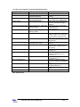
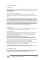
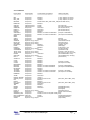
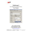
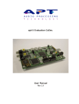
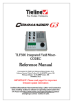
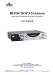
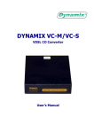
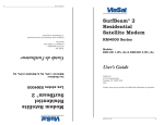
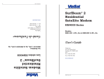
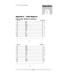
Technical Reference Manual
RaLex Solutions BVBA
Belgium
MDC.net V2.X
Issue November 2007
RaLex Solutions BVBA
Kolvenrodestraat 28
B 3080 Tervuren (Vossem)
Belgium
BTW BE 0873.213.004
Tel: +32 (0) 2 733 6051
Fax: +32 (0) 2 734 4510
Email: [email protected]
Internet: http://www.ralex.be/
All rights reserved. No part of this publication may be reproduced, stored in a retrieval system, or
transmitted, in any form or by any means, electronical, mechanical, photocopying, or otherwise,
without the prior written permission of the publisher. RaLex Solutions BVBA shall not be liable for any
errors contained in this manual or for incidental or consequential damages in connection with the
furnishing, performance, or use of this manual.
Pentium is a trademark of Intel Corporation.
Microsoft and Microsoft Windows are registered trademarks of their respective companies.
MySQL is a trademark of MySQL AB (for more information please visit:
http://www.mysql.com/company/trademark.html)
This manual and software described in it are protected by international copyright laws. Under the
copyright laws, this manual or the software may not be copied, in whole or part, without written consent
of RaLex Solutions BVBA, except to make a backup copy. It is not allowed to make copies for others,
whether or not sold, or to use the software on more than one microcomputer. Under the law, copying
includes translation into another language or format.
© 2005-2007 RaLex Solutions BVBA, Belgium
Page - 2-
1. What is MDC.net?.............................................................................................................................. 4
2. Database description ......................................................................................................................... 6
2.1. Tables not manageable by the Web Based Managemend ..................................................8
2.1.1. Routing tables..........................................................................................................9
2.2. Special features ..................................................................................................................10
2.2.1. QuickDials .............................................................................................................10
2.2.2. Shortcuts ...............................................................................................................10
3. Explanation of special topics............................................................................................................ 11
3.1. The Backend ......................................................................................................................11
3.2. Backend Tools....................................................................................................................11
3.2.1. Installing GiveIO ....................................................................................................11
3.3. Configuring the Backend ....................................................................................................11
3.3.1. Protocols................................................................................................................12
3.3.2. LDU Device Types.................................................................................................13
3.3.3. Connectors and pins allocation .............................................................................13
3.4. Remote routing ...................................................................................................................15
3.5. Cost accounting..................................................................................................................15
3.6. MDC.net Monitor.................................................................................................................15
3.7. MDC.net Scheduler ............................................................................................................15
4. Specific Device Behavior ................................................................................................................. 16
4.1. MAYAH Centauri ................................................................................................................16
4.2. CCS CDQ 1000 ..................................................................................................................17
4.3. AETA HifiScoop 3...............................................................................................................17
4.4. CCS CDQPrima..................................................................................................................17
4.5. Dialog4 VP-128...................................................................................................................18
4.6. Dialog4 VP-Pro ...................................................................................................................18
4.7. Dialog4 MusicTAXI MT-NET ..............................................................................................18
4.8. DHD Routing and MDC.net Router table configuration ......................................................19
4.9. TA 2124 DX/CP ..................................................................................................................19
4.10. AEQ Eagle ........................................................................................................................20
4.11. Prodys Pronto ...................................................................................................................20
4.12. WorldNet Milano ...............................................................................................................20
4.13. Sonifex NicaX ...................................................................................................................20
4.14. Telos Xstream ..................................................................................................................20
4.15. Tieline Commander G3 ....................................................................................................21
© 2005-2007 RaLex Solutions BVBA, Belgium
Page - 3-
1. What is MDC.net?
MDC.net stands for Multiple Device Control NETwork. It is a system to control and monitor devices in
a broadcast station. The basic idea is to control all devices - located anywhere - from any place.
Figure 1.1 shows the minimum
configuration for an MDC.net system. A
PC - from now on referred to as client and a device are connected to
MDC.net. From the client-side, the
device can now be controlled
completely. The client does not need to
know where the device is located, only
a user definable device name is
necessary, in order for MDC.net to do
Figure 1.1
the locating. Applications can use this
feature to search for a free device
anywhere in the system. Figure 1.2 shows a normal configuration for MDC.net. All components will be
explained on the following pages.
Figure 1.2
The MDC.net kernel provides the interface to the client. The kernel is implemented as a MSWindows® DLL and called the MDC Communications DLL (MDCCom.DLL). Thus all applications that
use MDC.net have to use the MS-Windows® environment. Programmers who are designing
applications for MDC.net use the functions within this DLL. The kernel uses Remote Procedure Calls
(RPC) to communicate with the MDC.net server. User authentication functions are available within the
kernel. A system administrator can grant rights to users and groups.
© 2005-2007 RaLex Solutions BVBA, Belgium
Page - 4-
All devices are connected to socalled Backends. These PCs handle the communication from the
MDC.net server to the devices and in vice versa. One Backend can theoretically handle up to 127
devices; the practical maximum depends on the performance of the PC and the type of devices
connected. MDC.net supports a broad range of device types. For each device type the Backend
contains a device specific driver. This implies that the MDC.net Backend provides a device-indepent
interface to the Server, so that the applications on the ClientPC don’t need to be aware of any devicespecific specialities. The device capabilities - that must be known by the ClientPC application - are
specified in the configuration database.
All PCs - ClientPCs as well as Backends- are connected to a server running the MDC.net Server
Service. The communication between all MDC.net parts relies on RPC via TCP/IP, which implies that
these communication services must be installed on all PCs. Furthermore MDC.net uses a MySQL™
database installed on the server to store the configuration and the state of the connected equipment.
In order for the RPC communication to operate and withthat allow the MDC.net Server Service to
communicate with all Backends and Clients a username and password combination must be created
on all MDC.net PCs in your network. These user credentials have to be equal on all PCs or one
domain useraccount can be used.
© 2005-2007 RaLex Solutions BVBA, Belgium
Page - 5-
2. Database description
MDC.net uses a MySQL database to store the configuration as well as the more dynamic device states
and routing information. Most of the MDC.net configuration can be managed using the Web Based
Management (WBM). For a more detailed description of the WBM, please follow the instructions in the
MDC.net User Manual. For a full control over your database as well as for the purpose of making
backups and restoring information the tool MySQL-Front® has been provided with your installation.
MySQL-Front offers a network connection to the MySQL database so that you can manage the
database from any workstation within your network.
When starting MySQL-Front you will be asked to connect to the proper database host. When working
on the MDC.net Server, you can just connect to "localhost", see the above picture. After connecting to
the appropriate host, you can view the tables by clicking the [+] in front of the name of the database.
Using the tabs "Host", "Database", "Table", "Data" and "Query" you can select the desired views.
The option "Data" is used to manually make changes in the tables of the database. "Query" can be
used to import updates and or restore previously made backups of the database.
can be used to confirm or revert the
When editing fields within the database the buttons and
change. To confirm the change you can also select a field on another row within the same table. Use
button to refresh the data within a table. To delete a record, the – button or <Ctrl>+<Del> can
the
be used.
© 2005-2007 RaLex Solutions BVBA, Belgium
Page - 6-
The option "Export tables…" from the Im-/Export menu allows you to create backups of your
database(s). To create a full backup of a database select the desired database and make sure that all
tables are selected. Also verify that the options 'Include "USE dbname"-Statement', 'Include "DROP
TABLE"-Statements, "Structure" and "Data" are selected and choose the filename for your database
backup.
Backups created in this way can be used to restore your database using the "Query" option as
mentioned above. To restore a database choose the option "Load from file…" from the right-mousemenu from the Query editor and select the previously stored database file. Choose the option "Run"
from the same menu to restore the complete database.
© 2005-2007 RaLex Solutions BVBA, Belgium
Page - 7-
2.1. Tables not manageable by the Web Based Managemend
Setting
RegistrationNumber
BaseDir
BackendLogDir
CCMSEndpoint
Default value
C:\Program
Files\RaLex\MDCnet
C:\Program
Files\RaLex\MDCnet\Log
http://localhost:18400
UserManagerWSDLEndpoint
http://localhost/AAC_SOAP/User
Manager.WSDL
UserManagerWSMLEndpoint
StatusUpdateInterval
http://localhost/AAC_SOAP/User
Manager.WSML
1000
MDCSchedulerPort
18402
MDCSchedulerWSDLDir
RedialDelay
C:\Program
Files\Arbor\AAC_SOAP
5
RouteTalkbackOnly
0
DisconnectPreparedGDU
1
DisconnectReservedGDU
0
DisconnectIfNoNumber
0
RouteDefaultAfterDisconnect
1
AllowTransfer
0
ClientTransparancy
55
Description
10 digit licensenumber
Points to the MDC.net installation
directory
Points to a Backend log directory
(same directory for all Backends)
Points to the Arbor CCMS interface
port for monitoring and logging
purposes
Points to the Arbor UserManager
Soap interface for
usermanagement
Currently not in use
Interval in milliseconds in which
multiple updates are considered as
a single update. Recommended
values are in the range 500…1500
The MDC.net (Scheduler) Soap
interface port
The MDC.net (Scheduler) Soap
directory
Time in seconds after which the
system issues a redial (when the
line is busy)
Perform only Talkback (retour)
routing (0 / 1)
Disconnect a prepared GDU if the
incoming number (CLI) is not
correct (0 / 1)
Disconnect incoming calls if a GDU
is reserved (0 / 1)
Disconnect a prepared GDU if
there is no number (CLI) available
(0 / 1)
Automatically route a default after
releasing a GDU (0 / 1)
Disabe or Enable the transfer
option
Client transparency (0..200)
Table globalsettings
© 2005-2007 RaLex Solutions BVBA, Belgium
Page - 8-
Setting
LPT1_ADR
LPT1_XOR
Default value
0x378
0x00
UNIREL1_ADR
UNIREL1_XOR
0x9800
0x0000
OPTOREL1_ADR
OPTOREL1_XOR
0x9800
0x0000
ADDA1_ADR
ADC10_CONV
ADC11_CONV
ADC12_CONV
ADC13_CONV
ADC10_OFFSET
ADC11_OFFSET
ADC12_OFFSET
ADC13_OFFSET
0xD000
0.0003051804379
0.0003051804379
0.0003051804379
0.0003051804379
0
0
0
0
Description
The Backends LPT-port address
Optional XOR value. Any bit set to 1 will be
inverted when the port is read
The Backends UniRel card address
Optional XOR value. Any bit set to 1 will be
inverted when the port is read
The Backends OptoRel card address
Optional XOR value. Any bit set to 1 will be
inverted when the port is read
The Backends ADDA card address
Conversion value for ADDA port 1
Conversion value for ADDA port 2
Conversion value for ADDA port 3
Conversion value for ADDA port 4
Offset value (volts) for ADDA port 1
Offset value (volts) for ADDA port 2
Offset value (volts) for ADDA port 3
Offset value (volts) for ADDA port 4
Table hardware
2.1.1. Routing tables
There are a number of tables involved to configure your router. These tables are:
• srcgroups
• studio
• routerinputs
• routeroutputs
• routercue
• routerexclude
To split inputs and outputs into groups and therefore making it possible to fit the router window to your
screen the tables srcgroups (for the inputs) and studio (for the outputs) allow grouping of in- and
outputs. The fields srcgroupnr (within the table routerinputs) and studionr (within the table
routeroutputs) map specific in- or outputs to these groups. When these fields contain a value of 0 the
in- or outputs are always visible in any group selection. To hide any in- or outputs from the Matrix
window set the field issource (for inputs) or isdest (for outputs) to 0 (default).
In order to display the correct default output-group for each workstation (e.g. the faders of a specific
studio) a mapping from a pc-name to a specific studio can be configured in the localsettings table.
When clearing a crosspoint a default (input) can be routed to the corresponding output. These defaults
can be configured in the table routeroutputs and allow configuration of a specific input for both left and
right channels. In order to automatically route these defaults, the field defaultdirection specifies the
direction to be routed and should contain one of the following values. Just add up these values when a
combination should be used.
Value
1
2
4
8
Direction
Incoming Left
Incoming Right
Talkback Left
Talkback Right
© 2005-2007 RaLex Solutions BVBA, Belgium
Page - 9-
The MDC.net system has a very powerfull routing system that allows not just crosspoints to be made,
but makes it possible to completely route all signals (forward and return, left and right) with a single
mouse-click. In order for the MDC.net routing system to fulfill this task the table routercue describes
the relationships between inputs and outputs (i.e. the incoming channels and their corresponding n-1
or talkback channels). This table is also used to display incoming and talkback crosspoints correctly.
2.2. Special features
Below you will find a description of special features that can be activated from within the MDC.net
database.
2.2.1. QuickDials
Setting the localsettingsnr setting in the table quickdials to 0 will make the selected quickdial global.
The global quickdials are displayed at all clients.
2.2.2. Shortcuts
Setting the studionr setting in the table shortcuts to 0 will make the selected shortcut global. The global
shortcuts are available at all clients.
© 2005-2007 RaLex Solutions BVBA, Belgium
Page - 10-
3. Explanation of special topics
3.1. The Backend
A dedicated 32-bit service version of the Backend has been developed for use with Windows® NT
based operating systems.
This Backend can be started using the autostart functionality of Windows® NT services before the
login window appears.
The syntax for the Backend ImagePath in the
HKEY_LOCAL_MACHINE\SYSTEM\CurrentControlSet\Services\MDCBackend command is:
BACKEND.EXE /ID <id> /DISPLAY <displaylevel> /LOGLEVEL <loglevel> /HISTORY <historysize>
/DEBUG
where <id> specifies the number for the Backend (hexnumber 1 .. F), <displaylevel> can be set to
increase the level of messages saved in the history and <loglevel> can be specified to increase the
level of messages stored in separate device logs. Generally, the higher the DisplayLevel used, the
lower the performance will be, but the more information is available. The number of lines saved in the
unit specific history window can be set using <historysize>. The larger <historysize>, the more memory
is needed to run the Backend. In addition a /DEBUG can be set, to log all screen messages and
communications. For specific unit debugging the enable debugging checkbox can be set from within
the physical units history window. These options should be used for debugging only. All the above
options can be more easily configured from the Backends configuration screen.
3.2. Backend Tools
There are a few shareware utillities that in some cases must be installed in order to start the Backend.
These utillities are needed to control relay, optocoupler and AD-DA cards.
3.2.1. Installing GiveIO
GiveIO is an utillity that allows the Backend to “talk” with some special controller cards like UniRel,
OptoRel and AD-DA cards. To install GiveIO, the driver giveio.sys has to be copied into your
%SystemRoot%\SYSTEM32\DRIVERS directory. In order to complete the installation, type the
following command at the command prompt:
INSTDRV GiveIO %SystemRoot%\SYSTEM32\DRIVERS\GIVEIO.SYS
Now check your Devices from the control-panel (NT4) or select Computer Management from the
Administrative tools menu (Windows 2000) and make sure the service starts automatically.
In order for the Backend to control the specific ports, the device address has to be located using the
PCIVIEW utillity. To use the PCIVIEW utillity, it has to be copied to a local harddisk.
Now find the card by selecting the PCI-slot and checking the Vendor and DeviceID.
Enter the appropriate values for LPTx_ADR, UNIRELx_ADR, OPTORELx_ADR or ADDAx_ADR for
the selected Backend in the hardware table of the MDC.net database.
Optionally for UniRel and OptoRel Cards a 16-bit XOR value can be specified within the same table in
order to invert inputvalues read from the port. The default value used is 0x0000.
3.3. Configuring the Backend
Specifying the protocols and the units connected to the different communication ports does the main
configuration of the Backend. This configuration can be done from the MDC.net Web Based
Management and is more detailed described in the MDC.net User Manual.
© 2005-2007 RaLex Solutions BVBA, Belgium
Page - 11-
3.3.1. Protocols
Protocol Name
===========
Port Description
============
Communications Configuration
=======================
MPC
MPC_2400
MPC_1200
MPC2MPC
Comport xxH
Comport xxH
Comport xxH
Comport xxH
9600,N,8,1
(C-Hop / SuperIO, HF-Control)
2400,N,8,1
(C-Hop / SuperIO, HF-Control)
1200,N,8,1
(C-Hop / SuperIO, HF-Control
Routed to MPC, MPC_2400 or MPC_1200 (Remote MPC Server)
BABYBLUE
CDQ1000
CDQ2000
CDQPRIMA
PRIMA LT
PRIMA LT+
DIALOG4
STUDIOSET1
STUDIOSET2
RE662
RE663
VPPRO
ZEPHYR
XSTREAM
MTAXI_NET
CENTAURI
HIFISCOOP3
EAGLE
PRONTO
SUPERLINK
SYSTEMBASE
TELOS_TWO1
TELOS_TWO2
MILANO
CENTAURI
NICA-X
Comport xxH
9600,N,8,1
Lptport/Uniport xxH
Parallel
Lptport/Uniport xxH
Parallel
Comport xxH
38400,N,8,1
Comport xxH
38400,N,8,1
Comport xxH
38400,N,8,1
Comport xxH
9600,N,8,1
Comport xxH
9600,N,8,1 or Routed to STUDIOSET2
Comport xxH
9600,N,8,1 or Routed to STUDIOSET1
Comport xxH
Comport xxH
Comport xxH
9600,N,8,1
Comport xxH
9600,N,8,1
IPport www.xxx.yyy.zzz:port
IPport www.xxx.yyy.zzz:port
IPport www.xxx.yyy.zzz:port
Comport xxH
9600,N,8,1
Comport xxH
38400,N,8,1
Comport xxH
9600,N,8,1
IPport www.xxx.yyy.zzz:port
Comport xxH
9600,N,8,1
IPport www.xxx.yyy.zzz:port
IPport www.xxx.yyy.zzz:port
Comport xxH
19200,N,8,1
IPport www.xxx.yyy.zzz:port
Comport xxH
9600,N,8,1
ASCOM110
CITAM
CITAM1
CITAM2
MAINSTREET
MAINSTR1
MAINSTR2
MATRACOM
TA2124DX
TA2124DX1
TA2124DX2
MINIDMON
Comport xxH
Comport xxH
Comport xxH
Comport xxH
Comport xxH
Comport xxH
Comport xxH
Comport xxH
Comport xxH
Comport xxH
Comport xxH
Comport xxH
AM16B
ROUTER_GLSNR5
GLSNR5_VX1010
NTP
NTP632
NTP_VX1010
SIEMENS
TESI
RM3200
RM4200
KLOTZ
KLOTZ_IP
BAS3232
INTERCEPT_SW1
INTERCEPT_SW2
DMTF_GENERATOR
DTMF_GEN
SOPHO
Comport xxH
38400,N,8,1
Comport xxH
1200,E,7,1
Comport xxH
Routed to Aurora VX-1010
(MPC, MPC_2400 or MPC_1200)
Comport xxH
9600,E,8,1
Comport xxH
9600,E,8,1
Comport xxH
Routed to Aurora VX-1010
(MPC, MPC_2400 or MPC_1200)
Comport xxH
38400,N,8,1
Comport xxH
9600,N,8,1
Comport xxH
9600,N,8,1
(DHD-RM3200 router)
Comport xxH
38400,N,8,1
(DHD-RM4200 router)
Comport xxH
(Klotz Digital)
IPport www.xxx.yyy.zzz:port
(Klotz Digital over IP)
Comport xxH
19200,N,8,1
(Philips / Thomson Router)
Comport xxH
Routed to Aurora VX-1010 (MPC or MPC_2400)
Comport xxH
Routed to Aurora VX-1010 (MPC or MPC_2400)
Lptport xxH
Parallel
(Internal DTMF Generator)
Comport xxH
2400,N,8,2
(Arbor DTMF Generator)
IPport www.xxx.yyy:zzz:port
(Sopho PABX)
9600,N,8,1
9600,N,8,1
9600,N,8,1
9600,N,8,1
9600,N,8,1
9600,N,8,1 or Routed to MAINSTR2
9600,N,8,1 or Routed to MAINSTR1
9600,N,8,1
1200,N,8,1
1200,N,8,1 or Routed to TA2124DX2
1200.N.8.1 or Routed to TA2124DX1
9600,N,8,1
© 2005-2007 RaLex Solutions BVBA, Belgium
Aditional Information
================
(Use Input=xxH)
(Use Input=xxH,Output=xxH)
(RS-232, No Protocol)
(RS-232, No Protocol)
(RS-232, No Protocol)
(First part of STUDIOSET)
(Second part of STUDIOSET)
(Dialog4)
(Use Telco PTP)
(Telos XStream over IP)
(MusicTaxi over IP)
(IP Communication)
(AT#BAU_X=4)
(AEQ Eagle)
(Prodys Pronto 1,2,3)
(IP Communication)
(SystemBase C400)
(First part of Telos Two over IP)
(Second part of Telos Two over IP)
(APT WorldNet Milano / Ohio)
(APT WorldNet Tokyo / Chicago)
(Sonifex Nica-X)
(First part of CITAM)
(Second part of CITAM)
(First part of MAINSTREET)
(Second part of MAINSTREET)
(First part of TA2124DX)
(Second part of TA2124DX)
Page - 12-
Protocol Name
===========
Port Description
============
Communications Configuration
=======================
Aditional Information
================
AURORA
VIRTUAL_IO
HFCONTROL
PARALLEL_IO
Comport xxH
Comport xxH
ADDAport xxH
OptoRelPort xxH
Routed to MPC, MPC_2400 or MPC_1200
9600,N,8,1 or Routed to MPC or MPC_2400
AD-DA / Parallel control
(Antenna / Receiver / Transmitter)
Parallel
(Direct IO)
3.3.2. LDU Device Types
The MDC.net applications recognize and are able to control the following unit types:
Type:
ENCODER
DECODER
TA (TERMINAL ADAPTER)
ROUTER
REMOTEROUTER
HFROUTER
ROTOR
RECEIVER
TRANSMITTER
DTMF_GENERATOR
Each type has its own set of specific commands, as could be read in chapter 1.
Usually a PDU device automatically refers to one or more specific LDU device type(s). Therefore, the
LDUs are configured automatically, when a physical device (PDU) is created.
3.3.3. Connectors and pins allocation
Pin 1 of a RJ-45 connector is the left-most pin when looking at the cable side of the connector and
keeping the clip down.
RJ-45 8 pin Adapter RJ-45 8p Adapter
at RJ-45 side
wire color
1
Blue
2
Orange
3
Black
4
Red
5
Green
6
Yellow
7
Brown
8
Gray or White
-
Signal name
DSR
RTS
SHIELD GND
TXD
RXD
SIGNAL GND
CTS
DTR
DCD
RI
DB-9
DTE
6
7
3
2
5
8
4
1
9
DB-9
DCE
4
8
2
3
5
7
6
1
9
DB-25
DTE
6
4
2
3
7
5
20
8
22
DB-25
DCE
20
5
3
2
7
4
6
8
22
To create a standard PC RS-232 connector compatible with the Digiboard standard, wire as follows:
PC (9-pol):
PC (25 pol):
DB-9 DTE MALE
DB-25 DTE MALE
© 2005-2007 RaLex Solutions BVBA, Belgium
Page - 13-
Following describes the RJ-45 adapter needed and its wiring when connected to a Digiboard:
PC (9-pol):
PC (25 pol):
DB-9 DCE FEMALE
DB-25 DCE FEMALE
Ascom110
TA2124DX
TA2124DX-MultiPoint
Telos Zephyr:
RE 662/663:
StudioSet:
DHD RM3200:
AETA Hifiscoop3
NTP
CDQPrima Ancillary
Prodys Pronto
SystemBase C400
WorldNet Milano
Sonifex NicaX
DB-25 DTE MALE
DB-25 DTE MALE
DB-9 DTE MALE
DB-9 DCE FEMALE
DB-25 DTE MALE
DB-9 DTE MALE
DB-9 DTE MALE
DB-9 DTE MALE
DB-9 DCE FEMALE
DB-9 DCE FEMALE
DB-9 DTE MALE
DB-9 DTE MALE ?
DB-9 DTE MALE
DB-9 DTE MALE
CDQ-Prima:
DB-9 MALE; Special wiring:
RJ-45 Adapter wire color
Insert at pin
Red
4
Green
9
Yellow
5
CITAM Supervisor port: RJ-12; Special wiring:
Citam RJ-12
Digiboard RJ-45
PC DB-9 Female
3
5
2 (green)
4
4
3 (red)
6
6
5 (yellow)
DTMF-Generator to Digiboard cable:
DTMF-Gen RJ-12 Digiboard RJ-45
3
6
4
4
CDQ-200x connectors for remote control are wired as follows:
OptoRel Signal
37 pol. Male
CCS CDQ200x Signal
CDQ2000 Pin
(9 pol. Male)
*
Output b0
1
Select A
2
Output b1
2*
Select B
3
Output b2
3*
Select C
4
Output b3
4*
Line 1
6
Output b4
5*
Line 2
7
Output b5
6*
Mode
8
Output b6
7*
Type
9
Output b7
8*
Remote Enable
1**
Ground
19
Ground
5
CDQ2001 Pin
(26 pol. HD Male)
11
7
5
2
4
6
10
1**
9,18,24
*
Pins 20…27 need to be grounded at 37 pol. Male connector.
In case of wiring problems Pin 1 (Remote Enable) may directly be connected to Pin 5 (Ground).
**
© 2005-2007 RaLex Solutions BVBA, Belgium
Page - 14-
CDQ-1000 and CDQ-200x Alarm detection cales are wired as follows:
OptoRel Signal
37 pol. Female
CDQ 1000 3,5mm Jack
CDQ 200x (9 pol. Female)
Input b0
1*
Tip
1
Ground
19
Ring
5
*
Pin 20 needs to be connected to Pin 37 (Vcc).
OptoRel resistorpack needs to be replaced by the proper value (470…2kOhm).
3.4. Remote routing
Remote Routing allows the switching of a router at a remote location. The information about the
remote router's connections is stored in the addressbook (each connection must be stored as a
separate address). The router can be accessed via a direct serial line or through the ancillary
datachannel of an audio connection. Alternatively there is the possibility that the Remote Router
switching is done by the terminal adapter, making use of special control signals within the ISDN
connection (as with the "RNC" version of TA2124DX) or as DTMF tones send via the audio
connection.
The TechInfo field in the addressbook is used to specify the information about the remote router
connection. The format of the field is:
[Inn] [Omm]
Where nn is an (optional) Inputnumber and mm is (optional) Outputnumber. The system sends a
remote routing command to the RemoteRouter device belonging to the GDU. If nn or mm is not
specified the default of 1 is taken. In practice this means that specifying "I03" for the techinfo will cause
the system to select input 3 on the remote router. This is normally enough.
3.5. Cost accounting
Costaccounting in Version 2 is not yet available.
3.6. MDC.net Monitor
MDC.net Monitor is a service application that can be used for advanced monitoring of the ISDN
connections. The monitor program allows the user to set switches uppon connection and
synchronisation and automatically releases the switches at synchronisation or connection loss.
Another feature of the Monitor application is the ability to set a switch and / or play a windows® wave
file if synchronisation has been lost.
3.7. MDC.net Scheduler
The MDC.net Scheduler is a service application that can be used in conjuction with any (web-based)
scheduler. It provides a flexible SOAP interface that can be used to allow automated codec
connections and (remote-) routing.
© 2005-2007 RaLex Solutions BVBA, Belgium
Page - 15-
4. Specific Device Behavior
4.1. MAYAH Centauri
Please configure the network-timeout setting in order to prevent the connection to become stale.
The timeout setting can be set from the menu: Settings / Timeouts / Remote Control. We
recommend a timeout of 90 seconds. Using Centauri Remote, this can be done using: Expert /
Direct Command and enter the command “time_remotecontrol”.
The next Commands will be transmitted to the MAYAH Centauri when the Codec settings are
changed:
"Enc_format Auto"
"Enc_bitrate <BitRate>"
"Enc_srate <SampleRate>"
Encoder DataMode:
1ch CCS …6ch CCS and 1ch H221 … 6ch H221
"Enc_format CCS"
"Enc_algo Mpegl2"
Encoder DataMode:
2ch Dlg4L2 …6 ch Dlg4L2:
"Enc_format Musictaxi"
"Enc_algo Mpegl2"
Encoder DataMode:
Unframed, 2ch RE …6ch RE:
"Enc_algo Mpegl2"
Encoder DataMode:
1ch J52 …6ch J52:
"Enc_algo AAC"
Encoder DataMode:
G722/H221 and G722:
"Enc_algo G.722"
Encoder DataMode:
2ch CCSL3 …6ch CCSL3:
"Enc_format CCS"
"Enc_algo Mpegl3"
Encoder DataMode:
2ch DLG4_L3 …6ch DLG4_L3:
"Enc_format Musictaxi"
"Enc_algo Mpegl3"
Encoder DataMode:
1ch Layer3, 2ch D4SL3 …6ch D4SL3,
2ch TelosL3 …6ch TelosL3:
"Enc_algo Mpegl3"
Encoder DataMode G711ALAW:
"Enc_algo G.711"
"ISDN_g711 alaw"
Encoder DataMode G711MLAW:
"Enc_algo G.711"
"ISDN_g711 ulaw"
© 2005-2007 RaLex Solutions BVBA, Belgium
Page - 16-
Encoder DataMode not G.722, G722/H221, G722NBT, G711ALAW or G711MLAW
Encoder AudioMode Stereo:
"Enc_mode Stereo"
Encoder AudioMode Joint Stereo:
"Enc_mode Joint"
Encoder AudioMode Dual Channel:
"Enc_mode Dual"
Encoder AudioMode Mono:
"Enc_mode Mono"
Encoder DataMode: G.722, G722/H221, G722NBT, G711ALAW or G711MLAW
"Enc_mode Mono"
Encoder Dependent YES
"Enc_slave Remote"
Encoder Dependent NO
"Enc_slave Local"
"Dec_slave Remote"
4.2. CCS CDQ 1000
The CDQ1000 is a codec that is on the market since the early nineties, before the MPEG2 standard
had been defined. Apart from this, there were misunderstandings about the interpretation of CRC
algorithm in MPEG1.
Therefore the older CDQ1000 codecs were not MPEG compliant in two aspects:
1.
Wrong CRC
2.
Proprietary 24kHz mode, instead of the MPEG2 standard
In newer versions these problems were solved, but to maintain compatibility with older systems, the
use of the correct algorithms could be set by a dipswitch at the back of the unit.
To set a CDQ1000 in MPEG compliant mode, you must set Dipswitches 6 and 8 to “ON” (up).
Test this using both 24 and 48 kHz. If it still doesn’t work, your CDQ1000 might be an early unit. In this
case it needs a firmware upgrade.
With the latest firmware it is advised to switch dipswitch 7 to “ON” as well, as this will provide
increased stability when using G.722.
4.3. AETA HifiScoop 3
The AETA HifiScoop 3 uses ScaleFactorCRC On and Off, to enable or disable the relay transmission
function.
A combination of Encoder InputMode and Encoder OutputMode is used for the HifiScoop 3 to set the
format for the audio interfaces. Configuration is done as follows:
Interface type
Analog:
AES/EBU Async
AES/EBU 32kHz
AES/EBU 48kHz
InputMode
Analog or Analog Unbalanced;
Digital or Digital SPDIF
Digital or Digital SPDIF
Digital or Digital SPDIF
OutputMode
Don’t care
External
32
48
4.4. CCS CDQPrima
© 2005-2007 RaLex Solutions BVBA, Belgium
Page - 17-
To set the CDQPrima to CDQ 1000 24kHz proprietary mode use DataMode 1ch CCS.
2ch CCS can be used to setup the CDQPrima into CDQ2000/2001 inverse multiplexing protocol.
Use 1ch … 6ch H221, 1ch... 6ch J52, 3ch ... 6ch CCS to use the CDQPrima H221 protocol.
1ch or 2ch nnnDISTRIBUTIONm is the CDQPrima Distribution mode, where nnn (G722, L2, CCS or
L3) is the used protocol and m (“empty”, 2 or 3) is the number of destinations.
Decoder Dependent Yes or No is used to switch the CDQPrima Decoder Independent No or Yes
setting.
4.5. Dialog4 VP-128
ISDNMode is used for Dialog4 codecs compatibility. Please refer to the Dialog4 User Manual for a
more detailed description.
Mode
R
DNR
DNRI
Compatibillity
MusicTaxi
CCS
Telos
4.6. Dialog4 VP-Pro
ISDNMode is used for Dialog4 codecs compatibility. Please refer to the Dialog4 User Manual for a
more detailed description.
Mode
R
C
DXI
Compatibillity
MusicTaxi
CCS CDQPrima
Telos
4.7. Dialog4 MusicTAXI MT-NET
ISDNMode is used for Dialog4 codecs compatibility. Please refer to the Dialog4 User Manual for a
more detailed description.
Mode
NRI
DR
DRI
DNR
DNRI
Compatibillity
CCS CDQPrima
Telos
G722 SRT
H221 (G722)
Auto
© 2005-2007 RaLex Solutions BVBA, Belgium
Page - 18-
4.8. DHD Routing and MDC.net Router table configuration
To configure the MDC.net router tables for inputs / outputs use the DHD slotnumber (1 or 2 digits)
followed by 1 digit of the corresponding connector and 2 digits for the input or output. E.g. Router input
/ output 10123 would be slot 10 (Madi) connector 1, input / output 23. These numbers correspond with
the export tables of the DHD system.
4.9. TA 2124 DX/CP
TA2124DX connected to MDC.net without MPP2000:
Port 1 (at.) and Port 2 (at:):
X1 &B8 &C1 &D0 &M7 #B1 #C1 #N #W0 S00=001
&W (= save config)
Control Port (at;):
V1 X1 &K1 &N0 &B0
Now change to 1200 baud
E0
&W (= save config)
TA2124DX connected to MDC.net with MPP2000:
Als zonder MPP2000
MPP2000 dipswitches:
DIP1: ON
DIP2: X (don't care, OFF = Keyboard enabled, ON = Keyboard disabled)
DIP3: ON
DIP4: ON
TA2124DX connected to DXD (dialer) without MPP2000:
Port 1 (at.) en Port 2 (at:):
X1 &B8 &C0 &D0 &M0 #B1 #C1 #N #W0 S00=001 (auto-answer)
&W (= save config)
Control Port (at;):
E1 V1 X1 &K1 &N0 &B3
Now change to 9600 baud
&W (= save config)
TA2124DX connected to DXD (dialer) with MPP2000:
Port 1 (at.) en Port 2 (at:):
X0 &B8 &C0 &D0 &M0 #B1 #C1 #N #W0 S00=001 (auto-answer)
&W (= save config)
Control Port (at;):
E1 V1 X1 &K1 &N0 &B3
Now change to 9600 baud
&W (= save config)
MPP2000 dipswitches:
DIP1: OFF
DIP2: OFF
DIP3: OFF
DIP4: OFF
© 2005-2007 RaLex Solutions BVBA, Belgium
Page - 19-
4.10. AEQ Eagle
In order to control the AEQ Eagle codec, its node address should be set to the same id as the unit-id
specified in MDCNET.CFG.
4.11. Prodys Pronto
The Datamode 2CH Dlg4L2 is used to configure the Prodys Pronto for MPEG Layer II Telos mode.
Inputmode Digital activates AES/EBU:EXT mode and Inputmode Digital SPDIF activates
AES/EBU:AUDIO for the Pronto 3. All other models just activate AES/EBU in either case.
When selecting 32 kHz samplingrate for models 1 and 2 48 kHz will be activated.
Dual codecmode is not yet supported.
4.12. WorldNet Milano
All MDC.net settings apply to encoder-settings only!
MDC.net setting
APTX
APTX16
APTX20
APTX24
APTXNO
Dependent Yes
Dependent No
Audiomode Mono
Audiomode Dual channel
WorldNet Milano
Settting
APTX-16
E-APTX-16
E-APTX-20
E-APTX-24
APTX-16
AutoSync On
AutoSync Off
WorldNet Monofill
Dual
Imux mode
Imux
Imux
Imux
Imux
Clear Mode
Comments
Only for Audiomode = Mono
Only valid in APTX mode
4.13. Sonifex NicaX
Only the first codec is supported.
All settings below are Encoder only settings. Codec-settings specified for the Decoder are ignored.
When Encoder Dependent YES is selected the NicaX will be configured for Auto Detect (mode 1).
Datamode APTX, APTX16, APTX20, APTX24 and APTXNO selects the APT ISDN mode. If the
Audiomode is set to anything but MONO, APT ISDN IMUX-S is selected. If however MONO is
selected, any bitrate higher than 64 kbit will select the APT ISDN IMUX-M mode. Clear-Mode is
selected otherwise. The Datamode G722, G722/H221, G722distribution and G722NBT will select the
G722 ISDN-M mode. Datamode DLG4L2, L2distribution and MPEGL2 will select the L2 ISDN-M mode
and the desired samplerate can be specified (24 or 48). Configuration of the Ancillary-data (Auxilary
Data Rate) is supported.
4.14. Telos Xstream
Prior to using the Telos Xstream in combination with the MDC.net Backend, the default login password
of the Telos has to be cleared. This can be done by setting-up a telnet session to the Telos and typing
the following command: "Login Telos -", without the quotation marks (“).
© 2005-2007 RaLex Solutions BVBA, Belgium
Page - 20-
4.15. Tieline Commander G3
In order for the MDC.net Backend Service to be able to control the Tieline Commander G3 the profiles
"ManDflt MonoPgm" and "ManDflt Stereo" must exist. These profiles are used to switch between Mono
and Stereo modes including the control of the internal audio-matrix.
The simultaneous use of the "POTS"-Interface and the "ISDN"-Interface is not supported.
In any "POTS"-mode the "bitrate"-selection sets the "Modem Max. Bitrate" and the "samplerate" is
ignored.
Please use the settings shown in the table below, to achieve the corresponding settings for the Tieline
Commander G3 codec. Decoder settings are not used to configure the Tieline Commander G3.
MDC.net Datamode
POTS
POTS-Music
POTS-Other
POTS-Voice
GSM-Music
GSM-Other
GSM-Voice
ISDN-Music
ISDN-Other
ISDN-Voice
G722
G722NBT
G722/H221
G711ALAW
G711MLAW
Any other
Any other
Any other
Any other
MDC.net Audiomode
Mono
Joint Stereo
Stereo
Dual Mono
Tieline Codec
selection
Music
Music
Other
Voice G3
Music
Other
Voice G3
Music
Other
Voice G3
G722
G722
G722
G711
G711
MP2 Mono
MP2 Joint Stereo
MP2 Stereo
MP2 Dual
© 2005-2007 RaLex Solutions BVBA, Belgium
Comment
"POTS"-Interface
"POTS"-Interface
"POTS"-Interface
"POTS"-Interface
"POTS"-Int. in GSM-LL mode
"POTS"-Int. in GSM-LL mode
"POTS"-Int. in GSM-LL mode
"ISDN"-Interface
"ISDN"-Interface
"ISDN"-Interface
"ISDN"-Interface
"ISDN"-Interface
"ISDN"-Interface
"ISDN"-Interface
"ISDN"-Interface
"ISDN"-Interface
"ISDN"-Interface
"ISDN"-Interface
"ISDN"-Interface
Page - 21-