1
Digi PortServer CM
User Manual
90000252_C
Digi International Inc. 2002. All Rights Reserved
The Digi logo is a trademark of Digi International Inc. All other brand and product names are the
trademarks of their respective holders.
Information in this document is subject to change without notice and does not represent a
commitment on the part of Digi International.
Digi provides this document “as is,” without warranty of any kind, either expressed or implied,
including, but not limited to, the implied warranties of fitness or merchantability for a particular
purpose. Digi may make improvements and/or changes in this manual or in the product(s) and/or
the program(s) described in this manual at any time.
This product could include technical inaccuracies or typographical errors. Changes are periodically
made to the information herein; these changes may be incorporated in new editions of the
publication.
2
Contents
Chapter 1 Network Configuration
5
Introduction to the PortServer CM ....................................................................................................................5
Supported Browsers ...........................................................................................................................................5
Discover Utility..................................................................................................................................................6
NetConfig Utility ...............................................................................................................................................7
Chapter 2 Configuring Serial Ports
8
Configure Port Settings......................................................................................................................................8
Configure Advanced Port Settings ....................................................................................................................9
Configure Port Monitoring Parameters............................................................................................................10
Configure Protocol Settings.............................................................................................................................11
Configure Authentication Settings...................................................................................................................11
Configure Port Buffering .................................................................................................................................12
Cluster PortServer CM Devices.......................................................................................................................14
Basic Concepts for Clustering Devices ...........................................................................................................14
Chapter 3 Web UI (User Interface)
16
Log On .............................................................................................................................................................16
Change the Password .......................................................................................................................................16
Navigate Web Interface (Navigation Bar) .......................................................................................................17
Chapter 4 Menus
20
Simplify Port Connections with digi_menu.....................................................................................................20
Create Menus Through the Web Interface.......................................................................................................21
The Connect Command Through the Command Line Interface .....................................................................24
Chapter 5 Creating Auto-Alerts and Notifications
25
Create Auto-Alerts ...........................................................................................................................................25
Syslog-ng .........................................................................................................................................................26
User Scenarios .................................................................................................................................................33
Chapter 6 System Administration
35
Users and Passwords........................................................................................................................................35
Shadow Password ............................................................................................................................................35
NTP Client Functionality.................................................................................................................................36
Packet Filtering Using ipchains .......................................................................................................................36
Contents
3
Chapter 7 Hardware Specifications
38
The RS-232 Standard.......................................................................................................................................38
Cable Length....................................................................................................................................................39
Connectors .......................................................................................................................................................39
Straight-Through vs. Crossover Cables ...........................................................................................................40
Choose Correct Cable ......................................................................................................................................40
Cable Diagrams................................................................................................................................................41
LED Information..............................................................................................................................................42
Working Inside the PortServer CM .................................................................................................................43
Safety Instructions ...........................................................................................................................................43
Chapter 8 Upgrading and Troubleshooting
44
Upgrading the Linux Kernel ............................................................................................................................44
Troubleshooting the PortServer CM................................................................................................................45
Single User Mode ............................................................................................................................................46
Hardware Test..................................................................................................................................................47
Port Conversation ............................................................................................................................................47
Test Signals Manually .....................................................................................................................................47
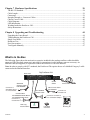
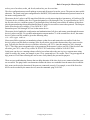
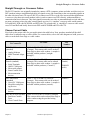
What Is In the Box
The following figure shows the main unit, accessories included in the package and how cables should be
connected. The loop-back connector is provided for convenience in case hardware tests are necessary. An
Ethernet cable (not supplied) is required to connect the PortServer CM to the network.
Note: In order to comply with FCC standards, the PortServer CM requires the use of a shielded Category 5 cable
connected to the Ethernet Interface
.
Digi PortServer CM
Back View
17
18
19
20
21
22
23
24
25
26
27
28
29
30
31
32
90-240VAC
Ethernet
10/100Base-T Console
1
Connect to a
SUN Netra Server
or a Cisco Router
2
3
5
6
7
8
9
10
11
12
13
14
P/N 76000639
Modem Cable
Hard Copy
Documentation
15
16
On/Off
Switch
SUN Netra
Crossover Cable
P/N 76000636
Console Cable
P/N 76000638 Female DB-25
P/N 76000658 Male DB-25
Connect to a
Console Port
Contents
4
Power Cable
DB-9 Console Cable
P/N 76000637
Connect to a
Console Port
Connect to a modem or
to a null-modem adaptor
Loop-Back
Connector
Mounting Kit
4
Introduction to the PortServer CM
Network Configuration
Chapter 1
Introduction to the PortServer CM ......................................................................................5
Supported Browsers .............................................................................................................5
Discover Utility....................................................................................................................6
NetConfig Utility .................................................................................................................7
Introduction to the PortServer CM
The PortServer CM is a Linux-based secure console access server running an embedded version of the Linux
operating system. Configuration of the PortServer CM is accomplished by either editing the pslave.conf text file
or using the web interface. The pslave.conf file can be edited with a scaled-down vi editor on the PortServer CM
or edited on another system. For users more familiar with a graphical interface, the new web interface provides a
solution for getting the PortServer CM configured quickly and easily.
The PortServer CM’s default IP address is 192.168.160.10 which you can change from either a telnet session or
through the web interface. Two other utilities are included to facilitate assigning IP settings to the terminal server
and connecting to the network. The Discover utility allows for quick assignment of IP settings using a web-based
Java applet and the NetConfig utility uses a command line interface to assign IP settings.
Supported Browsers
The following browsers are supported for use in configuring the PortServer CM through the web interface.
Browser & Version
Netscape 7.0 (Linux)
IE 6.0.26 (Win)
IE 6.0.26 (Win)
Netscape 4.78 (Linux)
Netscape 6.2 (Linux)
Chapter 1
Java Version
JRE 1.3.1_02 (comes w/ Netscape 7.0)
Microsoft (R) VM for Java, 5.0 Release 5.0.0.3802
JRE 1.4.1
Java 1.1.5
JRE 1.3.1_02 (comes w/ Netscape 6.2)
Network Configuration
5
Discover Utility
Mozilla 1.1 (Linux)
JRE 1.3.1 (comes w/ Mozilla 1.1)
Discover Utility
The Discover utility is a web-based Java applet that allows an administrator to quickly and easily assign IP
addresses, the Netmask, and Gateway settings to the PortServer CM from any workstation on the same network
as the PortServer CM. The Discover utility sends out a network broadcast and identifies responses from the
PortServer CM terminal servers.
The utility is available from the Digi website at http://cm.digi.com. The utility runs locally on the system you are
using and no information about your system or network is sent over the Internet.
To use the Discover utility do the following:
1. Open a web browser and enter the following URL in the address bar:
http://cm.digi.com
2. A security warning will be displayed, indicating that the applet is signed and asking if you want to install and
run the Discover utility. Choose Yes.
3. Choose Discover to have the Discover utility detect the PortServer CM on your network.
After completing the search, a new window will open listing the PortServer CM terminal servers found, the
firmware versions, and the MAC addresses. If IP, Netmask, and Gateway addresses have been previously
defined, these addresses will also be displayed.
4. Locate the MAC address of the PortServer CM you want to configure. The MAC address is listed on a white
sticker on the PortServer CM. Choose the Blink LEDs button for a visual verification of the device. The row
of serial port LEDs will flash when the Blink LEDs button is selected. Press the button again to stop the flashing LEDs.
5. Select the IP address cell and enter the IP address you wish to assign the PortServer CM. Enter the Netmask
and Gateway address settings as needed.
6. Choose Submit to save the new IP settings.
Choose the Locate button for a visual verification of the device. The row of serial port LEDs will flash when
the Locate button is selected. Press the Locate button again to stop the flashing LEDs.
Disable the Discover Utility
The system administrator may desire to disable the Discover utility so users cannot change network
configuration parameters. To disable the Discover utility, the administrator needs to modify two files, submit the
changes, and save the changes to the flash memory. To disable the Discover utility, use the Web Management
Interface and do the following:
1. Log on to the Web Management Interface with administrator rights (root).
2. From the navigation bar, choose Configuration > Edit Text File > and enter /etc/config_files in the
Filename cell and choose Submit.
3. Scroll to the end of the list and add the following line in the text box: /etc/inittab then choose Submit.
4. From the navigation bar, choose Configuration > Edit Text File > enter /etc/inittab in the Filename cell
and choose Submit.
5. Locate the following line ::once:/bin/xcelld and replace it with the following line
# ::once:/bin/xcelld and choose Submit. The # (number symbol) comments the line out.
6. From the navigation bar, choose Administration > Load/Save Configuration > Save to Flash.
7. Reboot the system and the Discover utility will no longer be available.
Chapter 1
Network Configuration
6
NetConfig Utility
NetConfig Utility
You can access the NetConfig utility through a telnet session by entering the default IP address, 192.168.160.10
or by connecting a terminal to the PortServer CM’s console port. At the logon prompt, enter the username root
and the password dbps. When the command prompt appears, enter netconfig to start the utility. Follow the
prompts to assign your IP settings.
Note:
The Netconfig utility automatically loads upon the first log in.
Console Port Parameters
Connect a personal computer or terminal to the PortServer CM using the console cable. If
you are using a personal computer, HyperTerminal can be used in the Windows operating
system or Kermit in the UNIX operating system. The terminal parameters should be set as
follows:
Serial Speed: 9600 bps
Data Length: 8 bits
Parity: None
Stop Bits: 1 stop bit
Flow Control: Hardware flow control or none
Ansi emulation
Note: If your terminal does not have ansi emulation, select vt100; then, on the CM, log in
as root and switch to vt100 by typing “TERM=vt100;export TERM”
When the PortServer CM boots properly, you will see a series of messages displayed as
the unit loads each operating system component followed by a logon banner. Log on as
root and dbps as the password. The PortServer CM runs Linux.
Chapter 1
Network Configuration
7
Configure Port Settings
Configuring Serial Ports
Chapter 2
Configure Port Settings........................................................................................................8
Configure Advanced Port Settings ......................................................................................9
Configure Port Monitoring Parameters..............................................................................10
Configure Protocol Settings...............................................................................................11
Configure Authentication Settings.....................................................................................11
Configure Port Buffering ...................................................................................................12
Cluster PortServer CM Devices.........................................................................................14
Basic Concepts for Clustering Devices..............................................................................14
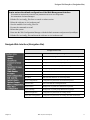
Configure Port Settings
You can configure the ports and other settings on the PortServer CM by modifying the pslave.conf file. This
chapter lists the parameters that need to be modified to configure the various settings on the PortServer CM. The
pslave.conf file is modified by using the vi editor built into the PortServer CM. You can also use another text
editor on another system to configure the settings on the PortServer CM. The following tables list the parameters
and a brief description of the values.
The file /etc/portslave/pslave.conf is specific to the PortServer
CM. There are three basic types of parameters:
• conf.* parameters are global or apply to the Ethernet interface
• all.* parameters are used to set default parameters for all ports
• s#.* parameters change the default port parameters for individual
ports.
Note: An all.* parameter can be overridden by an s#.* parameter
appearing later in the pslave.conf file (or vice-versa).
Chapter 2
Configuring Serial Ports
8
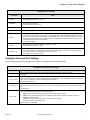
Configure Advanced Port Settings
Configure Port Settings
Parameter
Value
all.speed
The speed for all ports.
An example for this value is: 9600
all.datasize
The data size for all ports.
An example for this value is: 8
all.stopbits
The number of stop bits for all ports is 1.
all.parity
The parity for all ports is none.
all.dcd
DCD signal (sets the tty parameter CLOCAL). Valid values are 0 or 1. In a socket session, if all.dcd=0,
a connection request (telnet or ssh) will be accepted regardless of the DCD signal and the connection
and will not be closed if the DCD signal is set to DOWN. In a socket connection, if all.dcd=1 a connection request will be accepted only if the DCD signal is UP and the connection (telnet or ssh) will be
closed if the DCD signal is set to DOWN.
0 is the default value.
all.flow
This sets the flow control to hardware, software, or none.
An example for this value is: hard
all.socket_port
This defines a reverse telnet port value for the PortServer CM ports. The ‘+’ after the numerical value
causes the interfaces to be numbered consecutively. In this example, interface 1 is assigned the port
value 7001, interface 2 is assigned the port value 7002, etc.
An example for this value is: 7001+
Configure Advanced Port Settings
Use the following table for parameters and values to configure advanced port settings.
Configure Advanced Port Settings
Parameter
Value
all.prompt
This text defines the format of the logon prompt. Expansion characters can be used here.
%h login:
all.tx_interval
Valid only for protocols socket_server, socket_ssh, and raw_data. Defines the delay (in milliseconds) of
data received through a serial port and transmitted to the Ethernet . If not configured, 100ms is assumed. If
set to zero or a value above 1000, no buffering will take place.
The default value is 100.
all.idletimeout
Valid only for the protocols socket_server, socket_ssh, and raw_data. Specifies how long (in minutes) a
connection can remain inactive before it is cut off. If set to zero (the default), the connection will not time
out.
The default is 0.
all.sttyCmd
Tty settings after a socket connection to that serial port is established. Parameters must be separated by
space. The following example sets describe the options:
• -igncr which tells the terminal not to ignore the carriage-return on input
• -onlcr do not map newline character to a carriage return/newline character sequence on output
• opost post-process output,
• -icrnl do not map carriage-return to a newline character on input
all.sttyCmd -igncr -onlcr opost -icrnl
Default value is commented.
Chapter 2
Configuring Serial Ports
9
Configure Port Monitoring Parameters
SAVE SYSTEM UPDATES WITH THE MODIFICATIONS MADE TO THE FILE
Important!
To
To update
update the
the system
system with
with the
the modifications
modifications made
made to
to the
the files,
files, do
do the
the following:
following:
1.Confirm
be saved
to thetoflash
memory
are contained
in thein /etc/config_files
folder.
1.Confirm that
that all
all files
files should
that should
be saved
the flash
memory
are contained
the /etc/config_files
folder.
See the chapter Upgrading and Troubleshooting PortServer CM for a complete list of these files and
what
programs
which files.
See the
chapteruse
Upgrading
and Troubleshooting PortServer CM for a complete list of these files and
what
programs
use
which
files.
2.Enter the command:
2.Enter
the command:
saveconf
saveconf
This
command reads the /etc/config_files file and copies all the files listed in the file /etc/config_files
from
the ramdisk
to /proc/flash/script.
this command
reads
the /etc/config_files file and copies all the files listed in the file /etc/config_files
The
previous
contents
of the file /proc/flash/script will be lost.
from the ramdisk to /proc/flash/script.
The
previous
contents
of the by
fileentering
/proc/flash/script
will be lost.
3.Restart the digi_ras process
the command:
3.Restart
the digi_ras
signal_ras
hup process by entering the command:
signal_ras
hupis complete.
The
configuration
The configuration
is complete.
Note:
The restoreconf
does the opposite of saveconf, copying the contents of the
/proc/flash/script
file
to
the corresponding
in the ramdisk.
Thecontents
files on the
ramdisk are
Note: The restoreconf does
the opposite offiles
saveconf,
copying the
of the
overwritten.
The restoreconf
is run automatically
time the The
PortServer
booted.are
/proc/flash/script
file to the corresponding
files ineach
the ramdisk.
files onCM
theis
ramdisk
overwritten. The restoreconf is run automatically each time the PortServer CM is booted.
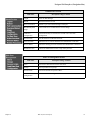
Configure Port Monitoring Parameters
Use the following table for parameters and values to configure port monitoring.
Configure Port Monitoring
Parameter
Value
all.sniff_mode
This parameter determines what other users connected to the very same port (see parameter
admin_users below) can see of the session of the first connected user (main session): in shows
data written to the port, out shows data received from the port, and i/o shows both streams. The
second and later sessions are called sniff sessions and this feature may be activated only when
the protocol parameter is set to socket_ssh or socket_server.
Out is the default setting.
all.admin_users
This parameter determines which users can open a sniff session, which is where other users
connected to the very same port can see everything that a first user connected is doing. The
other users connected to the same port can also cancel and take over the first user’s session .
When users want access per port to be controlled by administrators, this parameter is obligatory and authtype must not be none. This parameter can determine who can open a sniff session or cancel a previous session. User groups (defined with the parameter conf.group) can be
used in combination with user names in the parameter list.
An example is peter, john, user_group.
all.multiple_sessions
If all.multiple_sessions is configured as no, only two users can connect to the same port simultaneously. If all.multiple_sessions is configured as yes, more simultaneous users can sniff the
session or have read and/or write permission.
Chapter 2
Configuring Serial Ports
10
Configure Protocol Settings
Configure Protocol Settings
Use the following table for parameters and values to configure protocol settings.
Configure Protocol Settings
Parameter
Value
all.protocol
For the console server profile, the possible protocols are socket_server (when telnet is used),
socket_ssh (when ssh version one or two is used), raw_data (to exchange data in transparent mode
similar to socket_server mode but without telnet negotiation, breaks to serial ports, etc.)
Default value is socket_server
all.ipno
This is the default IP address of the PortServer CM's serial ports. The "+" indicates that the first
port should be addressed as 192.168.1.101 and the following ports should have consecutive values.
Any host can access a port using its IP address as long as a path to the address exists in the host's
routing table.
Default value is 192.168.1.101+
all.break_sequence
Send Break to the TTY when this string is received (ssh only).
Default value is break.
Configure Authentication Settings
The PortServer CM provides several authentication methods. You can set the parameters by editing the
pslave.conf file or from the web interface. The following table lists the various parameters used in configuring
the authentication settings. Information in the table will be helpful in choosing your authentication method and
values.
.
Configure Authentication Settings
Parameter
Value
all.authtype
There are several authentication type options: local (authentication is performed using the
/etc/passwd file), radius (authentication is performed using a Radius authentication server), TacacsPlus (authentication is performed using a TacacsPlus authentication server), none, local/radius
(authentication is performed locally first, switching to Radius if unsuccessful), radius/local (the
opposite of the previous option), RadiusDownLocal (local authentication is tried only when the
Radius server is down), local/TacacsPlus (authentication is performed locally first, switching to
TacacsPlus if unsuccessful), TacacsPlus/local (the opposite of the previous option), TacacsPlusDownLocal (local authentication is tried only when the TacacsPlus server is down). Note that this
parameter controls the authentication required by the PortServer CM. The authentication required by
the device to which the user is connecting is controlled separately.
The default is radius.
all.authhost1
This address indicates the location of the Radius/TacacsPlus authentication server and is only necessary if this option is chosen in the previous parameter. A second Radius/TacacsPlus authentication
server can be configured with the parameter all.authhost2.
An example is 200.200.200.2.
all.accthost1
This address indicates the location of the Radius/TacacsPlus accounting server, which can be used to
track how long users are connected after being authorized by the authentication server. Its use is
optional. If this parameter is not used, accounting will not be performed. If the same server is used
for authentication and accounting, both parameters must be filled with the same address. A second
Radius/TacacsPlus accounting server can be configured with the parameter all.accthost2.
An example is 200.200.200.2.
all.radtimeout
This is the timeout (in seconds) for a Radius/TacacsPlus authentication query to be answered. The
first server (authhost1) is tried "radretries" times, and then the second (authhost2), if configured, is
contacted "radretries" times. If the second also fails to respond, Radius/TacacsPlus authentication
fails.
An example is 3.
all.radretries
Defines the number of times each Radius/TacacsPlus server is tried before another is contacted.
The default, if not configured, is 5.
Chapter 2
Configuring Serial Ports
11
Configure Port Buffering
Configure Authentication Settings
Parameter
Value
all.secret
This is the shared secret necessary for communication between the PortServer and the Radius/TacacsPlus servers.
An example is Digi.
all.users
Restricts access to ports by user name. Access is restricted only to the users listed. An exclamation
mark restricts access to ALL except the users listed. In this example, the users joe, mark and members of user_group cannot access the port. A single comma and spaces/tabs may be used between
names. A comma may not appear between the ! and the first user name. The users may be local,
Radius or TacacsPlus. User groups (defined with the parameter conf.group) can be used in combination with user names in the parameter list. Notice that these are common users not administrators.
An example is joe, mark, user_group.
conf.group
Used to group users to simplify configuration of the parameter all.users later on. This parameter can
be used to define more than one group.
An example is group_name: user1, user2
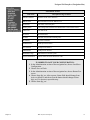
Configure Port Buffering
Use the following table for parameters and values to configure port buffering.
Configure Port Buffering
Parameter
s#.serverfarm
Value
Alias name given to the server connected to the serial port. The # sign is the port number.
An example is server_connected_serial5
A non zero value activates data buffering (local or remote, according to what was configured
in the parameter conf.nfs_data_buffering).
If local data buffering:
• a file is created on the PortServer CM
• this parameter means the maximum file size (in bytes)
• each time the maximum is reached the oldest 10% of stored data is discarded, releasing
space for new data (FIFO system) - circular file
all.data_buffering
If remote data buffering:
• a file is created through NFS in a remote server. All data received from the port is captured
in this file
• this parameter is just a flag to activate (greater than zero) or deactivate data buffering
• there's no maximum file size other than the one imposed by the remote server - linear file
This file can be viewed using the normal Unix tools (cat, vi, more, etc).
The default value is 0.
conf.nfs_data_buffering
Remote Network File System where data captured from the serial port will be written instead
of the default directory "/var/run/DB". The directory tree to which the file will be written must
be NFS-mounted. If data buffering is turned on for port 1, for example, the data will be stored
in the file ttyS1.data (or <serverfarm1>.data if s1.serverfarm was configured) in the directory
indicated by this variable (please see also Data Buffering section for more details). The remote
host must have NFS installed and the administrator must create, export, and allow reading/writing to this directory. The size of this file is not limited by the value of the parameter
s1.data_buffering, though the value cannot be zero since a zero value turns off data buffering.
The size of the file is dependent on the NFS server only (hard drive, partition size, etc.).
Default value is commented.
conf.facility
This value (0-7) is the local facility sent to the syslog. The file /etc/syslogng/syslog-ng.conf
contains a mapping between the facility number and the action.
The default value is 7.
all.syslog_buffering
When non zero, the contents of the data buffer are sent to the syslogng every time a quantity of
data equal to this parameter is collected. The syslog level for data buffering is hard coded to
level 5 (notice) and facility conf.DB_facility. The file /etc/syslog-ng/syslog-ng.conf should be
set accordingly for the syslog-ng to take some action
The default setting is 0.
Chapter 2
Configuring Serial Ports
12
Configure Port Buffering
Configure Port Buffering
Parameter
Value
conf.DB_facility
This value (0-7) is the local facility sent to the syslog with the data when syslog_buffering
and/or alarm are active. The file /etc/syslog-ng/syslogng.conf contains a mapping between the
facility number and the action.
The default value is 0.
all.DB_timestamp
A non zero value activates time stamp recording in the data buffering file. This parameter is
meaningful only if data buffering option is active. In case time stamp recording is on, input
characters will be accumulated until either a CR or LF character is received from the serial port
or the size of the accumulated data reaches 256 characters. Then the accumulated data will be
recorded in the data buffering file along with the current time.
The default is 0.
all.dont_show_DBmenu
When zero, a menu with data buffering options is shown when a nonempty data buffering file is
found. When 1, the data buffering menu is not shown. When 2, the data buffering menu is not
shown but the data buffering file is shown if not empty. When 3, the data buffering menu is
shown but without the erase and show and erase options.
The default is 1.
Chapter 2
Configuring Serial Ports
13
Cluster PortServer CM Devices
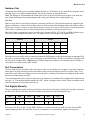
Cluster PortServer CM Devices
Clustering allows the networking together of PortServer CMs so that one master PortServer CM can be used to
access and manage all PortServer CMs on a LAN. The master PortServer CM can manage up to 512 serial ports
or have 15 slave PortServer CMs.
7303
7302
7035
7301
7034
7033
7003
7002
7001
Port Numbers
LAN
PortServer CM
Slave2
Ethernet IP
Address: 20.20.20.3
PortServer CM
Slave1
Ethernet IP
Address: 20.20.20.2
PortServer CM
Master
Ethernet IP
Address: 20.20.20.1
SecondaryAddress:
209.81.55.11 0
Management
Workstation
IP Address:
20.20.20.10
Router
Ethernet IP
Address: 209.81.55.111
Remote
Management
Workstation
Basic Concepts for Clustering Devices
The following information presents an overview of how to setup clustering on a network. The preceding diagram
should be used as a reference in configuring the PortServer CM for clustering. The Digi website also contains a
sample pslave.conf file to aide the user in the configuration process. To access this document, go to
http://support.digi.com/ and select Knowledge Base. Enter the keywords: portserver cm clustering.
You can cluster up to 512 ports or 15 slave devices.
There can be only one master device and it must have two IP addresses. One IP address should be unique to the
clustered network using conf.eth_ip and the other should be an IP address for the main network using
conf.eth_ip_alias. The subnet masks should also correspond to their IP addresses.
The unique IP settings for the clustered network is designed to protect the slave devices from computers
outside the main network gaining access.
Slave units have only one IP address unique to the clustered network. A typical clustered network might have the
master device with an IP address of 20.20.20.1 and slave devices numbered sequentially after that IP address, for
example 20.20.20.2, 20.20.20.3 and so on. See the preceding diagram.
The master device can use any type of authentication to handle the master and slave ports. Some authentication
options are: none, local, and radius.
The master device can use any protocol related to Console Management. Three common protocols are:
Chapter 2
Configuring Serial Ports
14
Basic Concepts for Clustering Devices
socket_server for telnet, socket_ssh for ssh, and socket_raw for raw telnet.
The slave configuration must set all.authtype to none and all.protocol to socket_server. The ports are inaccessible
otherwise. The actual serial port configuration for RADIUS, SSH, and other authentication protocols must be in
the master configuration file.
The master device’s pslave.conf file must list all the slave serial ports using the s# parameters. A PortServer CM
32 master device would have the first 32 ports designated as s1.tty through s32.tty. A second PortServer CM 32,
the first slave device, would have ports s33.tty through s64.tty, but these ports need the IP address of their host
plus the port numbering scheme that identifies them as using reverse-telnet or some other protocol. The first port
on the first slave device would be: s33.tty 20.20.20.2: 7033.
Remember ports 7001 through 7032 are on the master device.
The master device handles the configuration and authentication of all slave and master ports through the master
device’s pslave.conf file. To set radius authentication on port number 75 of the second slave device, the master
device’s pslave.conf file would be given the following entry:
s75.authtype radius
Slaves must follow a unique port numbering scheme so that slaves and masters do not conflict. Each slave
device’s pslave.conf file must set a unique value for all.socket_port in order that no other slave can access the
port. Typically, the first slave device would have all.socket_port 7033+ since the master has 7001+ through
7032+. This value must correspond to the s#.tty parameter in the master’s pslave.conf file. If the first slave has
all.socket_port 7033+, then s33.tty will be 20.20.20.2:7033 and s64.tty would be 20.20.20.2:7064.
Serial ports can also use a naming scheme called s#.serverfarm where the port is given a custom name string
which is used by digi_menu. An example is port s75.tty connected to a Cisco router. The s75.tty port appears on
digi_menu as Cisco router allowing the user to more easily identify the port and its purpose.
There are two troubleshooting features that can help determine if the slave devices are connected and the ports
are accessible. The ping feature can determine whether the slaves are reachable from the master device and the
digi_menu can be used to determine if the ports are connected correctly. For example, to test if the first slave
device can be reached by the master device, enter the command: ping 20.20.20.2.
Chapter 2
Configuring Serial Ports
15
Log On
Web UI (User Interface)
Chapter 3
Log On ...............................................................................................................................16
Change the Password .........................................................................................................16
Navigate Web Interface (Navigation Bar) .........................................................................17
Log On
1.
Open a browser (Netscape, Internet Explorer, etc.) and enter the URL or IP address of the PortServer CM’s
Ethernet interface. You may also use a secure socket layer by replacing http: with https: in the web URL
address section of your web browser.
Note: You can find the IP address of the PortServer CM by running the Discover utility. See Chapter 6 to configure new users.
2. Enter root in the username field and dbps in the password field to use the Web Configuration Manager.
Change the root password as soon as possible: the user database for the Web Configuration Manager is different than the system user database, so the root password can be different.
Change the Password
1.
2.
3.
4.
5.
6.
7.
Under Web User Management choose Users.
Select the radio button for the user root, then select Change Password.
Enter the new password twice and choose Submit.
The next page will require a new logon, enter root and the new password.
From the Web User Management section, choose Load/Save Configuration > Save > Configuration.
Next, go to Administration > Load/Save Configuration > Save to Flash.
To log out, choose the Administration > Log out.
Chapter 3
Web UI (User Interface)
16
Navigate Web Interface (Navigation Bar)
How to restore the default configuration of the Web Management Interface
This would be required only when the root password was lost or the configuration
file /etc/websum.conf was damaged.
1.
2.
3.
4.
5.
6.
7.
Edit the file /etc/config_files from a console or telnet session.
Delete the reference to /etc/websum.conf.
Save the modified /etc/config_files file.
Execute the command saveconf.
Reboot the system.
Enter into the Web Configuration Manager with the default username and password (root/dbps).
Edit the file /etc/config_files and insert the reference to /etc/websum.conf.
Navigate Web Interface (Navigation Bar)
Configuration Section
Link Name
Chapter 3
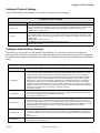
Description of Page Contents
General
Ethernet, DNS, Syslog, Name Service Access, Data Buffering.
Syslog
Displays vi editor for modifying the syslog file
Serial Ports
Configuration for the Portslave package
Connect to Serial Ports
Direct connection to a serial port, ports 1 through 512.
Serial Port Groups
Manages a group of ports
Host Table
Table of hosts in /etc/hosts.
Static Routes
Static routes defined in /etc/network/st_routes.
IP Chains
Static Firewall Chains in /etc/network/ipchains.
Boot Configurations
Configuration of parameters used in the boot process.
Edit Text File
Tool to read and edit a configuration file.
System Users
Management of system users defined in /etc/passwd.
System Groups
Management of system groups defined in /etc/groups.
Menu Configuration
Configuration of parameters for creating menus.
Auto-Alert Configuration
Configuration of parameters for creating auto-alert notifications.
Web UI (User Interface)
17
Navigate Web Interface (Navigation Bar)
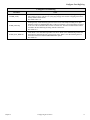
Administrative Section
Link Name
Description of Page Contents
Logout
Exits the Web Manager.
Reboot
Resets the Port Server CM.
Port Conversation
Enables a port conversation through a serial port.
Download/Upload
Image
Uses an FTP server to load and save a kernel image.
Load/Save
Configuration
Uses flash memory or an FTP server to load or save the CM's
configuration
Set Date/Time
Sets the PortServer CM's date and time.
Active Sessions
Shows the active sessions and allows the administrator to kill them.
Process Status
Shows the running processes and allows the adminsitrator to kill them.
Restart Processes
Allows the administrator to start or stop some processes.
Web User Management Section
Link Name
Chapter 3
Description of Page Contents
Users
List of users allowed to access the web server.
Groups
List of possible access groups.
Access Limits
List of access limits for specific URL’s.
Load/Save Web
Configuration
Load/Save web user configuration in /etc/websum.conf.
Web UI (User Interface)
18
Navigate Web Interface (Navigation Bar)
Information Section
Link Name
Interface Statistics
Statistics for all active interfaces.
DHCP Client
Host information from the DHCP server
Serial Ports
The status of all serial ports.
Routing Table
The routing table and allows the administrator to add or delete routes.
ARP cache
The ARP cache.
IP Chains
IP Chain Entries.
IP Rules
Firewall, NAT, and IP accounting rules.
IP statistics
IP protocol statistics.
ICMPstatistics
ICMP protocol statistics.
TCP statistics
TCP protocol statistics.
UDPstatistics
UDP protocol statistics.
RAM Disk Usage
The PortServer CM file system.
System Information
Various entries about the PortServer CMl
1.
2.
3.
4.
5.
Chapter 3
Description of Page Contents
IN ORDER TO SAVE YOUR CONFIGURATION:
In the Administration section of the navigation bar, choose Load/Save
Configuration.
Choose Save to Flash.
In the Administration section of the navigation bar, choose Restart Processes.
Choose Stop digi_ras. After a pause, Status field should change from
Active to Inactive, and the text on the button should change to Start
digi_ras. If it does not, repeat this step.
Choose Start digi_ras.
Web UI (User Interface)
19
Simplify Port Connections with digi_menu
Menus
Chapter 4
Simplify Port Connections with digi_menu.......................................................................20
Create Menus Through the Web Interface.........................................................................21
The Connect Command Through the Command Line Interface .......................................24
Simplify Port Connections with digi_menu
Use the digi_menu script to avoid typing long telnet or ssh commands. The digi_menu script is ready to use
immediately and requires no configuration. It presents a short menu with the names of the servers connected to
the serial ports of the PortServer CM. The server is selected by its corresponding number. Only ports configured
for console access (protocols socket_server or socket_ssh) will be presented.
Enter digi_menu with no command line options. This command displays the default menu.
Serial Console Server Connection menu
1 Lucy
2 Snoopy
3 Chris
4 Ringo
5 ttyS5
6 ttyS6
7 ttyS7
8 ttyS8
Type 'q' to quit, a valid option [1-8], or anything else to refresh:
Selecting option 2 will telnet/ssh to the server Snoopy. If a name is present in the serverfarm parameter for a port,
that name will appear. Otherwise, ttySN is used where N is the port number.
The digi_menu script has the following command line options:
-p: Displays IP Address and TCP port instead of server names:
Serial Console Server Connection menu
1 10.1.2.3 7001
2 10.1.2.3 7002
3 10.1.2.3 7003
4 10.1.2.3 7004
5 10.1.2.3 7005
6 10.1.2.3 7006
Type 'q' to quit, a valid option [1-8], or anything else to refresh:
-i: Displays Local IP assigned to the serial port instead of server names:
Chapter 4
Menus
20
Create Menus Through the Web Interface
Serial Console Server Connection menu
1 192.168.1.101
2 192.168.1.102
3 192.168.1.103
4 192.168.1.104
5 192.168.1.105
6 192.168.1.106
7 192.168.1.107
8 192.168.1.108
Type 'q' to quit, a valid option [1-8], or anything else to refresh:
-u name: Username to be used in ssh/telnet command. The default username is the one used to log on to the
PortServer CM.
-h: lists script options
Assigning Names to Ports
Ports may be assigned names to identify their destination or purpose. The names will appear in menus instead of
the generic ttySN names. Use the following procedure to name ports.
Open a web browser and access the Web Management Interface by entering the name or IP address of the
PortServer CM in the address bar.
1. Log on as root.
2. In the Configuration section of the navigation bar, choose Serial Ports.
3. From the Logical Ports drop down box, choose the port you wish to name, then choose Submit.
4. Enter the new name in the Server Farm parameter field (near the bottom of the page in the SSH section) and
choose Submit.
5. Repeat steps 4 and 5 for each port you wish to name.
6. In the Administration section of the navigation bar, choose Load/Save Configuration.
7. Choose Save to Flash.
8. In the Administration section of the navigation bar, choose Restart Processes.
9. Choose Stop digi_ras. After a pause, Status field should change from Active to Inactive and the text on the
button should change to Start digi_ras. If it does not, repeat this step.
10. Choose Start digi_ras.
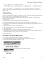
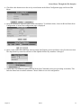
Create Menus Through the Web Interface
To create menus and submenus using the web interface, do the following:
1. Choose Menu Configuration from the Configuration section of the web interface menu.
2. Choose Add Menu under the Menu Configuration section.
.
3.
Enter a name for the new menu in the Menu Name box and choose Submit.
Chapter 4
Menus
21
Create Menus Through the Web Interface
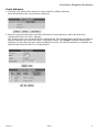
4.
Check the radio button next to the newly created menu on the Menu Configuration page and choose Edit
Menu.
5.
Enter the information requested under Menu Information. To add menu items, choose Add from Menu Item
Configuration. A menu item configuration page is displayed.
6.
Enter a name in the Item Label box from the Menu Item Display section and choose a key for the menu item.
The drop down key menu lists all letters of the alphabet followed by numbers 1 through 9.
7.
Choose the Go to Submenu option from the Menu Item Command section (see preceding screenshot.) This
links the Menu Item to another submenu. Choose Submit to save the configuration.
Chapter 4
Menus
22
Create Menus Through the Web Interface
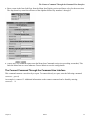
Create Submenus
1.
Check the radio button for the menu you want to modify by adding a submenu.
Menu information for the selected menu is displayed.
2.
Enter the requested information in the Menu Information section and choose Add in the Menu Item
Configuration section to create a submenu.
The example below is for a menu titled The Command Menu. The Command Menu already has one submenu
and one command listed in the Menu Item Configuration column. The configure submenu is hyperlinked
indicating it can be edited and more submenus added if necessary. The reboot command is a Command, not a
Submenu and can not be edited. It is not hyperlinked.
Chapter 4
Menus
23
The Connect Command Through the Command Line Interface
3.
Enter a name in the Item Label box from the Menu Item Display section and choose a key for the menu item.
The drop down key menu lists all letters of the alphabet followed by numbers 1 through 9.
4.
Choose the Go to Submenu option from the Menu Item Command section (see preceding screenshot.) This
links the Menu Item to a new submenu. Choose Submit to save the configuration.
The Connect Command Through the Command Line Interface
This command connects a user directly to a port. To connect directly to a port, enter the following command:
connect port#
An example is, connect 15. Additional information on the connect command can be found by entering:
connect -h
Chapter 4
Menus
24
Create Auto-Alerts
Chapter 5
Creating Auto-Alerts and Notifications
Create Auto-Alerts .............................................................................................................25
Syslog-ng ...........................................................................................................................26
User Scenarios ...................................................................................................................33
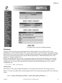
Create Auto-Alerts
Auto-Alerts can be configured from the web interface. Creating an Auto-Alert is a three step process of creating
a filter, linking the filter to specified ports, and adding a notification feature. To create an Auto-Alert, do the
following:
1. On the web interface main page under the Configuration menu, choose Auto-Alert Configuration.
2. Choose Add Filter > assign the filter a name > Submit.
3. Check the radio button next to the filter you just created and choose Edit Filter.
4. Enter the parameters for the filter > Submit.
5. Under the Link Configuration menu choose Add Link, then the ports you want to filter. Choose Submit.
You must check the radio button before selecting an individual port or port range. All Ports is selected by
checking the radio button only.
6. To add a notification, select Add Notification and choose either email address or SNMP Trap by selecting the
appropriate radio button and entering the required information. Choose Submit.
7. To save the configuration to flash memory, under the Administration menu choose Load/Save Configuration >
Save to Flash.
The configuration is saved. To start the auto-alert processes immediately, you must reboot the PortServer CM.
.
Chapter 5
Creating Auto-Alerts and Notifications
25
Syslog-ng
Screenshot of the Auto-Alert Configuration page
Syslog-ng
Syslog-ng is an advanced syslog configuration feature which enables the user to define specific source
information to be read or filtered such as, files, remote syslogd clients, or local messages. Syslog-ng uses filters
defined by the user to search for syslog level, syslog facility, string matching, or program generation. When the
filters detect pertinent information, they send the filtered information to a defined destination such as a file,
program, or a remote syslogd server.
The Syslog configuration is stored in the /etc/syslog-ng/syslog-ng.conf file and automatically starts when the
PortServer CM is booted. Changes to the configuration result in the syslog-ng process needing to re-read the
configuration. The user must enter the following command to prompt the syslog-ng process to re-read the
configuration files.
$ killall -HUP syslog-ng
Global Options
The PortServer CM syslog configuration supports several options that control how the syslog-ng process
behaves. To specify an option in the syslog configuration file (/etc/syslog-ng/syslog-ng.conf) use the following
syntax:
options { option_name(option_parameter); option_name(option_parameter); … };
Chapter 5
Creating Auto-Alerts and Notifications
26
Syslog-ng
The following option_name and option_parameter options may be used:
time_reopen(n):
time_reap(n):
sync_freq(n):
mark_freq(n):
log_fifo_size(n):
chain_hostname(yes/no):
long_hostname(yes/no):
use_time_recvd(yes/no):
use_dns(yes/no):
gc_idle_threshold(n):
gc_busy_threshold(n):
create_dirs(yes/no):
owner(username):
group(groupname):
perm(mask):
The time to wait before a dead connection is re-established.
The time to wait before an idle destination file is closed.
The number of lines buffered before written to file. The file is
synchronized when this number of messages has been written to it.
The number of seconds between two MARKS lines.
The number of lines fitting to the output queue.
Enable/disable the chained hostname format.
Enable/disable the chained hostname format.
Use the time a message is received instead of the one specified in the
message.
Enable/disable DNS usage. Syslog blocks on DNS queries, therefore
enabling DNS may lead to a Denial of Service (DoS) attack.
Sets the threshold value for the garbage collector when Syslog is idle.
Garbage collection phase starts when the number of allocated objects
reaches this number. [Default: 100]
Sets the threshold value for the garbage collected when Syslog is busy.
Garbage collection phase starts when the number of allocated objects
reaches this number. [Default: 100]
Enable/disable creating non-existing directories.
Set the owner of any created files to the one specified. [Default: root]
Set the group of any created files to the one specified. [Default: root]
Set the permission mask of the created file to the one specified.
[Default: 0600]
Source Definition
Source definitions define from where Syslog reads information. Multiple source definitions may be defined with
each using a variety of source drivers as explained below. To define a source in the syslog configuration file,
/etc/syslog-ng/syslog-ng.conf, use the following syntax:
source <identifier> { source_driver([source_params]); source_driver([…]); … };
The identifier must be a uniquely defined name for this source. No two source definitions may share the same
identifier.
The following source_driver and source_params definitions may be used:
internal():
Description: Messages generated internally in syslog-ng.
Parameters: None
Options:None
Chapter 5
Creating Auto-Alerts and Notifications
27
Syslog-ng
unix_stream(filename [options]):
unix_dgram(filename [options]):
Description: Syslog opens an AF_UNIX socket on the specified filename and begins listening
on the interface and socket for messages.
Parameters:
filename: The name of the file to open an AF_UNIX socket
Options:
owner(name): The owner of the file to specify
group(name): The group of the file to specify
perm(mask): The permission mask of the file to specify
keep-alive(yes/no): Enables/disables whether to keep connections opened when
syslog-ng is restarted. This can only be specified with
unix_stream. [Default: yes]
max-connections(n): The limit on the number of simultaneously opened
connections. This can only be specified with unix_stream.
[Default: 10]
Examples:
The following example receives messages from local syslogd clients:
source sysl { unix_stream(“/dev/log”); };
tcp([options]):
udp([options]):
Description:
Parameters:
Options:
Syslog opens listening connections on the TCP or UDP interfaces and begins
listening for messages. These definitions do not require source parameters since
by default they bind to 0.0.0.0:514 in order that syslog-ng listens on all available
interfaces on the remote syslog port.
None
ip(<ip-address>):
Bind to the IP address identified. [Default: 0.0.0.0]
port(<port-number>): Bind to and listen on the TCP or UDP port. [Default: 514]
max-connections(n): The limit on the number of simultaneously opened
connections. [Default: 10]
Examples:
The following example listens for syslog messages from a syslog client at 10.0.0.1:
source s_udp { udp( ip(10.0.0.1); port(514); ); };
file(filename):
Description:
Parameters:
Syslog opens the specified file and begins reading messages.
filename:
The name of the file to read messages.
Examples:
The following example will receive messages from the Linux kernel:
source s_kernel { file(“/proc/kmsg”); };
Chapter 5
Creating Auto-Alerts and Notifications
28
Syslog-ng
Filter Definitions
Filter definitions define how Syslog handles information in order to know when to send source definitions to
destination definitions. Multiple filter definitions may be defined each using a variety of filter expressions as
explained below. To define a filter in the syslog configuration file /etc/syslog-ng/syslog-ng.conf use the
following syntax:
filter <identifier> { filter_expression(filter_parameter) };
The identifier must be a uniquely defined name for this filter. No two filter definitions may share the same
identifier.
The following filter_expression and filter_params definitions may be used:
facility(facility_code):
Description: Selects messages based on their facility codes.
Parameters:
facility_code:
The facility code for the syslog message. The following
facility codes may be used:
info: Information messages
daemon: Server messages
kern: Kernel messages
auth: Authentication messages
authpriv:Private authentication events using data with
privileged or sensitive information
news: News messages
mail: Mail messages
local[0-7]: Local user-defined message
Examples:
The following examples explain various ways to use facility:
filter f_daemon { facility(daemon); };
filter f_kern { facility(kern); };
filter f_debug { not facility(auth, authpriv, news, mail); };
filter f_syslog_buf { facility(local[0+<conf.DB_facility>]); };
level(level_code):
priority(priority_code):
Description: Selects messages based on their priorities.
Parameters:
priority_code:
The priority code for the syslog message. The following
priority codes may be used:
info: Informations
warn: Warnings
emerg: Emergencies
Chapter 5
Creating Auto-Alerts and Notifications
29
Syslog-ng
Examples:
The following examples explain various ways to use priorities:
filter f_messages { level(info..warn); };
filter f_emergency { level(emerg); };
program(program_name):
Description: Selects messages based on the program that generated it.
Parameters:
program_name:The name of the program to match.
Examples:
host(host_name):
Description:
Parameters:
The following examples explain various ways to use the programs.
filter f_sshd_debug {not program(“sshd”) or not level(debug); };
Selects messages based on the hostname field of the log message.
host_name:
match(string):
Description:
Parameters:
The hostname to match
Selects messages based on a string in the log message
string:
The string to match in the message
Examples:
The following examples explain how to match a string “named”:
filter f_named { match(“named”); };
Destination Definitions
Destination definitions define where Syslog sends information that it receives. Multiple destination definitions
may be defined with each using a variety of destination drivers as explained below. To define a destination in the
syslog configuration file /etc/syslog-ng/syslog-ng.conf use the following syntax:
destination <identifier> { destination_driver([destination_param]); destination_driver([…]); … };
The identifier must be a uniquely defined name for this destination. No two destination definitions may share
the same identifier.
The following destination_driver and destination_params definitions may be used:
unix_stream(filename):
unix_dgram(filename):
Description: Syslog sends a message on the specified AF_UNIX socket.
Parameters:
Chapter 5
Creating Auto-Alerts and Notifications
30
Syslog-ng
filename: The name of the file shere Unix datagram or Unix socket messages are
sent.
tcp(“ip-address” [options]):
udp(“ip-address” [options]):
Description: Syslog sends messages to the specified remote host which are typically remote
syslog servers.
Parameters:
ip-address:
The IP-Address of the remote host where messages are sent.
Options:
port(<port-number>):Where the TCP or UDP port are connected. [Default: 514]
Examples:
The following example sends the messages to the syslogd server located at
10.0.0.1
destination d_udp { udp(“10.0.0.1” port(514)); };
file(filename [options]):
Description: Syslog sends received messages out to the specified file. This is one of the most
important destination drivers and includes several advanced configurations. The
destination filename may include macros that get expanded when the message is
written. This allows the filename to be dependent on the type of message.
Parameters:
filename:
The name of the file to write to. Since the state of this file
must be tracked by syslog-ng, it consumes some memory
for each file. Therefore, if no new messages are written to a
file within 60 seconds (controlled by the time_reap global
option), the file is closed and the state is freed. The
following macros may be used:
$HOST:
The name of the source from where the message originated.
$FACILITY:
The name of the facility with which the message was
tagged.
$PRIORITY:
The priority of the message.
$LEVEL:
Same as $PRIORITY.
$PROGRAM:
The name of the program that sent the message.
$YEAR:
Year the message was sent.
$MONTH:
Month the message was sent.
$DAY:
Day the message was sent.
$HOUR:
Hour the message was sent.
$MIN:
Minute the message was sent.
$SEC:
Second the message was sent.
$TAG:
Equal to $FACILITY/$LEVEL.
$FULLHOST:
The name of the source host and source driver:
<source-driver>@<hostname>.
Chapter 5
Creating Auto-Alerts and Notifications
31
Syslog-ng
$MSG/$MESSAGE: The message that was received.
$FULLDATE:
The date the message was sent.
Options:
log_fifo_size(n):
sync_freq(n):
encrypt(yes/no):
compress(yes/no):
owner(name):
group(name):
perm(mask):
The number of entries in the output file.
The file is synchronized when this number of messages is
written to it.
Encrypt the resulting file.
Compress the resulting file with zlib.
The owner of the file.
The group of the file.
The permission mask of the file.
Examples:
The following example sends a message to the console:
destination d_console { file(“/dev/ttyS0”); };
The following example writes the message a system file:
destination d_message { file(“/var/log/messages”); };
usertty (username):
Description:
Parameters:
Syslog sends the message to the terminals of the logged-in user
username:
The message is sent to each terminal to which the user is
logged.
Examples:
program (program_name program_arguments):
Description: Syslog does a fork() and then executes the given program with the specified
arguments sending the message to the stdin of the program.
Parameters:
program_name:
The name of the program.
program_arguments: The arguments to send to the program.
Examples:
The following example sends the message to all root-logged in sessions:
destination d_userroot { usertty(“root”); };
Connecting Definitions
After source, filter, and destination definitions have been defined, they must be connected together in order that
Syslog knows which sources to read from, which filters to filter them on, and which destinations to send them to.
Multiple syslog connections may be defined with each using any variety of previous definitions. To define a
syslog connection in the syslog configuration file, /etc/syslog-ng/syslog-ng.conf, use the following syntax:
log { source(source_definition_id); source(source_definition_id); …
filter(filter_definition_id); filter(filter_definition_id); …
Chapter 5
Creating Auto-Alerts and Notifications
32
User Scenarios
destination(destination_definition_id); destination(destination_definition_id); ...};
The source_defintion_id, filter_definition_id, and destination_defintion_id must refer to a previous defined
identifier. See the previous sections on how to define a source definition, filter definition, and destination
definition.
Examples:
The following example sends all messages received from local syslog clients to the console:
log { source(sysl); destination(d_console); };
The following example sends only those messages with alert level that are received from local syslog clients and
sends them to the logged in root user:
log { source(sysl); filter(f_alert); destination(d_userroot); };
The following example writes all messages with facility levels info, notice, or warning that are received from
local and remote syslog clients. The messages are written to the /var/log/messages file:
log { source(sysl); source(s_udp); filter(f_messages); destination(d_messages); };
The following example sends all messages with a kernel facility that are received from local and remote syslog
clients and sends them to a remote syslogd server:
log { source(sysl); source(s_udp); filter(f_kern); destination(d_udp); };
User Scenarios
Below are some common user scenarios and how to set up the necessary configuration on the PortServer CM.
These examples may be used directly or as a template for a more advanced configuration. Please refer to
previous sections for information on how to define the configuration.
Syslog Buffering
Syslog buffering is used in order to send port-generated messages and system messages to a remote syslog
server.
The following configuration is required in “/etc/portslave/pslave.conf” in order to make the configuration work.
# Data Buffering Facility
conf.DB_facility 1
all.syslog_buffering100
The following configuration is required in the Syslog Configuration file /etc/syslog-ng/syslog-ng.conf.
Local Syslog Clients
source src { unix_stream(“/dev/log”); } ;
# Filter Expressions(local1 matches the conf.DB_facility value)
# If you change conf.DB_facility, make sure to change localN so that N matches
filter f_buffering (facility(local) and level(notice); };
Chapter 5
Creating Auto-Alerts and Notifications
33
User Scenarios
# Remote Syslog Server Destinations
destination d_buffering { udp(“10.0.0.1”); } ;
# Send only Syslog_buffering messages to remote server
log { source(src); filter(f_buffering); destination(d_buffering); } ;
Multiple Syslog Server
Multiple syslog servers allow you to send various messages to various syslog servers. You can send all the
messages to all the servers or you can send certain messages to only certain servers giving you the greatest
flexibility.
The following configuration is required in “/etc/portslave/pslave.conf” in order to make the configuration work.
# Facility
conf.facility
The following configuration is required in the Syslog Configuration file “ /etc/syslog-ng/syslog-ng.conf”.
Local Syslog Clients
source src { unix_stream(“/dev/log”); };
# Remote Server 1 at IP=10.0.0.1 Port=Default
destination d_udp1 { udp(“10.0.0.1”); } ;
# Remote Server2 at IP=10.0.0.2 Port=1999
destination d_udp2 { udp(“10.0.0.2” port(1999)); };
# Filter Messages from Facility Local1 and Level Info to Warning
# If conf.facility in pslave.conf changes, then local1 must change to
# localN where N matches the value of conf.facility
filter f_local1 {facility(local1) and level1(info..warn) };
# Filter Messages from facilitylocal1 and Level Err to Alert
# If conf.facility in pslave.conf changes, then local1 must change to
#localN where N matches the value of conf.facility
filter f_critic { facility(f_local1) and level (err..alert) } ;
# Send Info, Notice, and Warning Messages to Remote Server 1
log { source(src); filter(f_local); destination( d_udp1); } ;
# Send Error, Critical, and Alert Messages to Remote Server 2
log {source(src), filter(f critic), destination(d_udp2); } ;
Chapter 5
Creating Auto-Alerts and Notifications
34
Users and Passwords
System Administration
Chapter 6
Users and Passwords..........................................................................................................35
Shadow Password ..............................................................................................................35
NTP Client Functionality...................................................................................................36
Packet Filtering Using ipchains .........................................................................................36
Users and Passwords
A username and password are necessary to log in to the PortServer CM. The user “root” is predefined, with a
password “dbps”. A new password should be configured as soon as possible to avoid unauthorized access. Enter
the command:
passwd
to create a password for the root user.
To create a regular user (without root privileges), use the commands:
adduser user_name
passwd user_password
To log out enter logout at the command prompt.
Shadow Password
The PortServer CM uses a Shadow Passwords feature for increased security. Typically, Linux passwords are
stored in the /etc/passwd file allowing unauthorized users easy access to a computer system’s or the network’s
user passwords. The shadow password feature encrypts or encodes the passwords and stores them in a root-only
accessible file named /etc/shadow.
Chapter 6
System Administration
35
NTP Client Functionality
NTP Client Functionality
In order for the PortServer CM to work as a NTP (Network Timer Protocol) client, the IP address and either
hostname or domain name of the NTP server must be set in the file /etc/hosts. To edit the file, use vi editor and
from the command line enter vi /etc/hosts.
Once in the file, add the following syntax ipaddress_NTPserver ntphost.
An example is: 199.26.5.33 ntphost. Save the file and exit the vi editor.
Next, enter vi /etc/timezone at the command line. Depress the “i” key to enter insert mode and enter the
appropriate Greenwich Standard Time difference. For the Central Time Zone of the United Stated, the entry
would be: GST+6. France, which is an hour earlier than GST would enter: GST-1. Save the file and exit the vi
editor. Lastly, enter saveconf from the command line to save the changes to flash memory.
Packet Filtering Using ipchains
The PortServer CM uses the Linux utility ipchains to filter IP packets entering, leaving and passing through its
interfaces. An ipchains tutorial is beyond the scope of this manual. For more information on ipchains, see the
ipchains man page (not included with the PortServer CM).
The syntax of the ipchains command is:
ipchains - command chain [-s source] [-d destination] [-p protocol] [-j target] [-i interface]
where command is one of the following:
A - Add a condition or rule to the end of the chain. Note that the order in which a condition appears in a chain can
modify its application and the first rule added to a chain is processed first, etc.
D - Delete a condition from the chain. The condition must match exactly with the command’s arguments to be
deleted.
R- Replace a condition in the chain.
I - Insert a condition in a specified location in the chain.
L - List all conditions in the chain.
F - Flush (remove) all conditions in the chain.
N - Create a new chain.
X - Deletes a user-created chain
P - Policy applied for default handling
chain is one of the following:
input - filters incoming packets
output - filters outgoing packets
forward - filters packets which are not created by the PortServer CM and are not destined to the PortServer CM
user_created_chain - a previously defined (or in the process of being defined) chain created using the N
command described above.
The output chain controls which packets are sent. A packet can be accepted by the input chain, but then rejected
by the output chain. Likewise, the forward chain controls which packets will be routed. The input chain controls
incoming packet filtering. The packet is either destined for the router or for another computer. In the latter case,
the packet is processed by the forward chain. Packets that pass through the forward chain will then be processed
by the output chain.
source and destination have the following format:
[!] address[/ mask] [!][ port[:port]]
! : reverses the definition, resulting in the opposite.
Chapter 6
System Administration
36
Packet Filtering Using ipchains
address: host or network IP
port: defines a specific port
port:port: defines a range of ports
If a source or destination is not specified then 0.0.0.0/0 is used.
protocol is one of the following: tcp, udp, icmp, all or a protocol number (see the file /etc/protocols for a list).
target is one of the following:
ACCEPT
DENY
the name of another chain
interface is:
eth0 (the Ethernet interface is the only option on the PortServer CM) Lists do not need to be associated to an
interface, so this option may be omitted.
To save changes made using the ipchains command, execute fwset. This command will save the filter
configuration in the file /etc/network/firewall and then save the file in flash memory.
To delete the changes made (before fwset is executed) execute fwset restore to return to the lists previously saved
in /etc/network/firewall. Only the lists previously saved using fwset will then be defined. This command is
executed at boot to invoke the last configuration saved.
Another option is to edit the file /etc/network/firewall (or another file) directly, following the syntax defined in
the file itself. If the file is edited in this way, the command fwset cannot be used to save and restore the
configuration.
Use:
ipchains-save > file_name to save the lists in file_name
updatefiles file_name to save file_name to flash memory
ipchains-restore < file_name to restore the lists to the configuration in file_name
An example of the use of ipchains for a console access server
If the administrator wishes to restrict access to the consoles connected to the PortServer CM to a user on the
workstation with IP address 200.200.200.4, a filter can be set up as shown below.
ipchains -P input ACCEPT
ipchains -P output ACCEPT
ipchains -P forward ACCEPT
ipchains -A input -p tcp -s ! 200.200.200.4 -d 0.0.0.0/0 23 -j DENY
ipchains -A input -p tcp -s ! 200.200.200.4 -d 200.200.200.1 7001:7032 -j DENY
ipchains -A input -p tcp -s ! 200.200.200.4 -d 0.0.0.0/0 22 -j DENY
Chapter 6
System Administration
37
The RS-232 Standard
Hardware Specifications
Chapter 7
The RS-232 Standard.........................................................................................................38
Cable Length......................................................................................................................39
Connectors .........................................................................................................................39
Straight-Through vs. Crossover Cables .............................................................................40
Choose Correct Cable ........................................................................................................40
Cable Diagrams..................................................................................................................41
LED Information................................................................................................................42
Working Inside the PortServer CM ...................................................................................43
Safety Instructions .............................................................................................................43
The RS-232 Standard
RS-232C, EIA RS-232, or simply RS-232 refer to a standard defined by the Electronic Industries Association in
1969 for serial communication. RS-232 was defined to connect Data Terminal Equipment, (DTE, usually a
computer or terminal) to Data Communication Equipment (DCE, usually a modem):
DTE —> RS-232 —> DCE —> communication line –> DCE —> RS-232 –> DTE
RS-232 is now mostly being used to connect DTE devices directly (without modems or communication lines in
between). While that was not the original intention, it is possible with some wiring tricks. The relevant signals
(or wires) in a RS-232 cable, from the standpoint of the computer (DTE) are:
• Receive Data (RxD) and Transmit Data (TxD) – The actual data signals
• Signal Ground (Gnd) - Electrical reference for both ends
• Data Terminal Ready (DTR) - Indicates that the computer (DTE) is active Data
• Set Ready (DSR) - Indicates that the modem (DCE) is active.
• Data Carrier Ready (DCD) - Indicates that the connection over the communication line is active
• CTS (Clear to Send, an input) – Flow control for data flowing from DTE to DCE
• RTS (Request to Send, an output) – Flow control for data flowing from DCE to DTE
Not all signals are necessary for every application, so the RS-232 cable may not need all 7 wires.The RS-232
Chapter 7
Hardware Specifications
38
Cable Length
interface defines communication parameters such as parity, number of bits per character, number of stop-bits and
the baud rate. Both sides must be configured with the same parameters. That is the first thing to verify if you
think you have the correct cable and things still do not work. The most common configuration is 8N1 (8 bits of
data per character, no parity bit included with the data, 1 stop-bit to indicate the end of a character). The baud rate
in a RS-232 line translates directly into the data speed in bits per second (bps). Usual transmission speeds range
between 9600 bps and 19200bps (used in most automation and console applications) to 115,200 bps (used by the
fastest modems).
Cable Length
The total capacitance of a cable affects the integrity of transmitted data. As a rule of thumb, the total capacitance
of a cable (including the connectors) should not exceed 2500 pF. Serial interface cable is usually rated in Pico
Farads per foot. Therefore, if a cable has a capacitance of 50 pF/ft, and the connectors are 100 pF each, the
maximum recommended cable length is 46 feet. If the cable is rated at 12.5 pF/ft, the maximum recommended
cable length is 184 feet, and 5 pF/ft cable can be run up to 460 feet. In situations where low-capacitance cable
(e.g. Category 5) is unavailable, or very long cable runs are required, “short-haul” modems, available from
suppliers such as Black Box, can be used to increase the effective range of the RS-232 interface. Short-haul
modems are similar to standard modems, except that they are connected directly to each other via a cable instead
of going through a telephone circuit.
Connectors
The connector traditionally used with RS-232 is the 25-pin D-shaped connector (DB-25). Most analog modems
and most older computers and serial equipment use this connector. The RS-232 interface on DB-25 connector
always uses the same standard pin assignment. The 9-pin D-shaped connector (DB-9) saves some space and is
also used for RS-232. Most new PC COM ports and serial equipment (specially when compact size is important)
uses this connector. RS-232 interfaces on DB-9 connectors always use the same standard pin assignment. The
telephone-type modular RJ-45 plug and jack are very compact, inexpensive and compatible with the phone and
Ethernet wiring systems present in most buildings and data centers. Most networking equipment and new servers
use RJ-45 connectors for serial communication. Unfortunately, there is no standard RS-232 pin assignment for
RJ-45 connectors. Every equipment vendor has its pin assignment. Most connectors have two versions. The ones
with pins are “male” and the ones with holes are “female”.
RS-232
Signal
Name/Function
(Input/Output)
DB-25 pins
(Standard)
DB-9 pins
(Standard)
RJ-45 pins
(PortServer CM)
Chassis
Safety Ground
1
Shell
Shell
TxD
Transmit Data (O)
2
3
3
RxD
Receive Data (I)
3
2
6
DTR
Data Terminal Ready (O)
20
4
2
DSR
Data Set Ready (I)
6
6
8
DCD
Data Carrier Detect (I)
8
1
7
RTS
Request To Send (O)
4
7
1
CTS
Clear To Send (I)
5
8
5
Chapter 7
Hardware Specifications
39
Straight-Through vs. Crossover Cables
Straight-Through vs. Crossover Cables
The RS-232 interface was originally intended to connect a DTE (computer, printer and other serial devices) to a
DCE (modem) using a straight-through cable (all signals on one side connecting to the corresponding signals on
the other side one-to-one). We can use RS-232 to connect two DTEs as is the case in most modern applications.
A crossover (also known as a null-modem) cable is used to connect two DTEs directly, without modems or
communication lines in between. They data signals between the two sides are transmitted and received and there
are many variations on how the other control signals are wired. A “complete” crossover cable would connect
TxD with RxD, DTR with DCD/DSR, and RTS with CTS on both sides. A “simplified” crossover cable would
cross TxD and RxD and locally short-circuit DTR with DCD/DSR and RTS with CTS.
Choose Correct Cable
First, look up the proper cable for your application in the table below. Next, purchase standard off-the-shelf
cables from a computer store or cable vendor. For custom cables, refer to the cable diagrams to build your own
cables or order them from Digi or a cable vendor.
To Connect To
Use Cable
DCE DB-25 Female
(standard)
• Analog Modems
• ISDN Terminal Adapters
Cable 1 – RJ-45 to DB-25 M straight-through
(Custom). This custom cable can be ordered
from Digi or other cable vendors. A sample is
included with the product (“straightthrough”).
76000639
DTE DB-25 Male or
Female (standard)
• Serial Terminals
• Old PC COM ports
• Most serial printers
• Some Console Ports
• Most automation
devices
Cable 2 – RJ-45 to DB-25 F crossover
(custom). This custom cable can be ordered
from Digi or other cable vendors. A sample is
included with the products (“Console”).
76000638
(female)
DTE DB-9 Male
(standard)
• Newer PC COM ports
• Most Mice and pointing Devices
• Some automation
devices
Cable 3 – RJ-45 to DB-9 F crossover
(custom). This custom cable can be ordered
from Digi or other cable vendors. A sample is
included with the products (console).
76000637
DTE RJ-45 Netra (custom)
• Sun Netra Console
Ports
• Cisco Console Ports
Cable 4- RJ-45 to RJ-45 crossover (custom)
76000636
This custom cable can be ordered from Digi or
cable vendors using the provided wiring
diagram.
Chapter 7
Hardware Specifications
Part
Number
76000658
(male)
40
Cable Diagrams
Cable Diagrams
Before using the following cable diagrams refer to the tables above to select the correct cable for your
application. Sometimes, crossover cables are wired slightly differently depending on the application. A
“complete” crossover cable would connect the TxD with RxD, DTR with DCD/DSR, and RTS with CTS across
both sides. A “simplified” crossover cable would cross TxD and RxD and locally short-circuit DTR with
DCD/DSR and RTS with CTS.
Most of the diagrams in this document show the “complete” version of the crossover cables, with support for
modem control signals and hardware flow control. Applications that do not require such features have just to
configure NO hardware flow control and NO DCD detection on their side. Both ends should have the same
configuration for better use of the complete version of the cables.
Digi CM RJ-45 to DB-25 Male, Straight Through
Application: It connects Digi CM products (serial ports) to modems and other DCE RS-232 devices.
.
RJ-45
Male
DB-25
Male
TxD 3
RxD 6
Gnd 4
TxD 2
RxD 3
Gnd 7
DTR 2
DSR 8
DCD 7
DTR 20
DSR 6
DCD 8
R TS 1
CTS 5
R TS 4
CTS 5
DB-25Male
RJ-45
Digi CM RJ-45 to DB-25 Female, Crossover (P/N 76000638 and P/N 76000658)
Application: It connects the PortServer CM (serial ports) to console ports, terminals, printers, and other DTE RS232 devices.
CoC
Cnoosnos
noleles
ol
e
DB-25Female/Male
RJ-45
Chapter 7
RJ-45
Custom
DB-25
F/M
TxD 3
RxD 6
Gnd 4
RxD 3
TxD 2
Gnd 7
DTR 2
DSR 8
DCD 7
DSR 6
DCD 8
DTR 20
RTS 1
CTS 5
CTS 5
RTS 4
Hardware Specifications
41
LED Information
Digi CM RJ-45 to DB-9 Female, Crossover (P/N 76000637)
DB-9 Female
CrC
Corosrsss
o
ss
Application: It connects Digi CM products (serial ports) to console ports, terminals, printers, and other DTE RS232 devices.
RJ-45
RJ-45
Custom
DB-9
Female
TxD 3
RxD 6
Gnd 4
RxD 2
TxD 3
Gnd 5
DTR 2
DSR 8
DCD 7
DSR 6
DCD 1
DTR 4
RTS 1
CTS 5
CTS 8
RTS 7
Digi CM RJ-45 to Netra RJ-45, Crossover (P/N 76000636)
Usually used in console management applications to connect Digi CM products to a Sun Netra server or to a
Cisco product.
SUN
N
ET
RA
RJ-45
Custom
RJ-45
Netra
TxD 3
RxD 6
Gnd 4
RxD 6
TxD 3
Gnd 4
DTR 2
DCD 7
DSR 7
DTR 2
R TS 1
CTS 5
CTS 8
R TS 1
/C
IS
CO
Dig
i
RJ-45
RJ-45
LED Information
The Digi PortServer CM has a frontal array of multiple LEDs. Below is a brief explanation of what each LED
represents.
Note: All 32 serial port Ready LEDs will flash when the Discover utility Locate box is selected.
LED Title
Definition
Collision
Indicates a collision on the Ethernet bus. Infrequent flashing is normal, frequent flashing indicates a saturated Ethernet bus.
Link
This LED should be on continually indicating the unit is properly terminated
on the network.
CPU
This LED blinks at a rate of one second on/one second off.
100BT
This light is on if the Ethernet link is connected to other 100Base-T equipment and is working at 100 Mbps. If not, the LED will be off.
RX
Indicates the unit is receiving data. This light should be blinking continually.
TX
Indicates the unit is transmitting data.
Ready
Indicates a connection to the port has been made.
RX
Indicates the unit is receiving data.
TX
Indicates the unit is transmitting data.
Serial Port LEDs
Chapter 7
Hardware Specifications
42
Working Inside the PortServer CM
Working Inside the PortServer CM
NOTICE: Do not attempt to service the PortServer CM yourself, except following the instructions from Digi
Technical Support personnel. In such a case, first perform the following actions:
• Turn off the PortServer CM.
• Ground yourself by touching an unpainted metal surface at the back of the equipment before touching anything inside your equipment.
Replacing the Battery
A coin-cell battery maintains date and time information. If you have to repeatedly reset time and date
information after turning on your PortServer CM, replace the battery.
CAUTION: A new battery can explode if it is incorrectly installed. Replace the 3 Volt CR2032 battery only
with the same or equivalent type recommended by the battery manufacturer. Discard used batteries
according to the battery manufacturer’s instructions.
Safety Instructions
CAUTION: Do not operate your PortServer CM with the cover removed.
• In order to avoid shorting out your PortServer CM when disconnecting the network cable, first unplug the
cable from the equipment and then from the network jack. When reconnecting a network cable to the equipment, first plug the cable into the network jack, and then into the equipment.
• To help prevent electric shock, plug the PortServer CM into properly grounded power source. The cable is
equipped with 3-prong plug to help ensure proper grounding. Do not use adapter plugs or remove the grounding prong from the cable. If you have to use an extension cable, use a 3-wire cable with properly grounded
plugs.
• To help protect the PortServer CM from transients in electrical power, use a surge suppressor, line conditioner,
or uninterruptible power supply.
• Be sure that nothing rests on the PortServer CMs cables and that the cables are not located where they can be
stepped on or tripped over.
• Do not spill food or liquids on your PortServer CM. If it gets wet, contact Digi Technical Support.
• Do not push any objects into the openings of your PortServer CM. Doing so can cause fire or electric shock by
shorting out interior components.
Keep your PortServer CM away from heat sources. Also, do not block cooling vents.
Chapter 7
Hardware Specifications
43
Upgrading the Linux Kernel
Chapter 8
Upgrading and Troubleshooting
Upgrading the Linux Kernel ..............................................................................................44
Troubleshooting the PortServer CM ..................................................................................45
Single User Mode ..............................................................................................................46
Hardware Test ....................................................................................................................47
Port Conversation ..............................................................................................................47
Test Signals Manually........................................................................................................47
Upgrading the Linux Kernel
The files added by Digi to the standard Linux files are in the /proc/flash directory. They are:
• boot_ori - original boot code
• boot_alt - alternate boot code
• syslog - event logs (not used by Linux)
• config - configuration parameters, only the boot parameters are used by the boot code
• zImage - Linux kernel image
• script - file where all PortServer CM configuration information is stored
To upgrade the Linux kernel provided in the PortServer CM, ftp the new zImage file on top of the zImage file in
the /proc/flash directory.
[root@portserver_cm /root]# cd /proc/flash
[root@portserver_cm flash]# ftp [ftp server name]
[root@portserver_cm flash]# cd [directory containing zImage file]
[root@portserver_cm flash]# bin (change to binary mode)
[root@portserver_cm flash]# get zImage
Reboot to activate the new Linux kernel. This can be confirmed by entering the following command at the
command prompt:
cat /proc/version
the Linux kernel version is displayed.
Chapter 8
Upgrading and Troubleshooting
44
Troubleshooting the PortServer CM
Troubleshooting the PortServer CM
If the PortServer CM booted properly, the interfaces can be verified using ifconfig and ping. If ping does not
work, check the routing table using the command route. Of course, all this should be tried after checking that the
cables are connected correctly.
As mentioned earlier, the file /etc/config_files contains a list of files acted upon by saveconf and restoreconf. If a
file is missing, it will not be loaded onto the ramdisk on boot. The following table lists files that should be
included in the /etc/config_files file and which programs use each.
File
Program
/etc/securetty
telnet, login, su
/etc/issue
getty
/etc/getty_ttyS0
login (via console)
/etc/hostname
tcp
/etc/hosts
tcp
/etc/host.conf
tcp
/etc/nsswitch.conf
dns
/etc/resolv.conf
dns
/etc/config_files
saveconf
/etc/passwd
login, passwd, adduser...
/etc/group
login, passwd, adduser...
/etc/ssh/ssh_host_key.pub
sshd
/etc/ssh/sshd_config
sshd
/etc/ssh/ssh_config
ssh client
/etc/ssh/ssh_host_key
sshd (ssh1)
/etc/ssh/ssh_host_key.pub
sshd (ssh1)
/etc/ssh/ssh_host_dsa_key
sshd (ssh2)
/etc/ssh/ssh_host_dsa_key.pub
sshd (ssh2)
/etc/snmp/snmpd.conf
snmpd
/etc/portslave/pslave.conf
digi_ras, portslave, CM configuration information
/etc/network/ifcfg_eth0
ifconfig eth0, digi_ras, rc.sysconf
/etc/network/ifcfg*
ifconfig, digi_ras, rc.sysinit
/etc/network/ifcfg_lo
ifconfig lo, digi_ras, rc.sysinit
/var/run/radsession.id
radinit, radius authentication process
/home
adduser, passwd
/etc/network/st_routes
ifconfig, digi_ras, rc.sysconf
If any of the files listed in /etc/config_files is modified, the PortServer CM administrator must execute the
command saveconf before rebooting the PortServer CM or the changes will be lost. If a file is created (or a file
name altered), its name must be added to this file before executing saveconf and reboot.
Chapter 8
Upgrading and Troubleshooting
45
Single User Mode
Single User Mode
The PortServer CM has a single user mode when:
• After the name or password of the user with root privileges is lost or forgotten
• After an upgrade or downgrade leaves the PortServer CM unstable
• After a configuration change leaves the PortServer CM inoperative or unstable
Type the word single (with a blank space before the word) during boot using a console connection. This
cannot be done using a telnet or other remote connection. The initial output of the boot process is shown below.
Entry Point = 0x00002120
loaded at: 00002120 0000D370
relocated to: 00300020 0030B270
board data at: 003052C8 0030537C
relocated to: 002FF120 002FF1D4
zImage at: 00008100 0006827E
relocated to: 00DB7000 00E1717E
initrd at: 0006827E 0024F814
relocated to: 00E18000 00FFF596
avail ram: 0030B270 00E18000
Linux/PPC load: root=/dev/ram
After displaying “Linux/PPC load: root=/dev/ram”, the PortServer CM waits approximately 10 seconds for user
input. This is where the user should type “single”. When the boot process is complete, the Linux prompt will
appear on the console:
[root@(none) /]#
If the password or username was forgotten, execute the following commands:
passwd
saveconf
reboot
For configuration problems, the user has two options:
Edit the file(s) causing the problem with vi, then execute the commands:
saveconf
reboot
Reset the configuration by executing the commands:
echo 0 > /proc/flash/script
reboot
If the problem is due to an upgrade or downgrade, a second downgrade or upgrade will be necessary to reverse
the process. First, the network must be initialized in order to reach a ftp server. Execute the following script,
replacing the parameters with values appropriate for your system. If your ftp server is on the same network as the
CM, the gw and mask parameters are optional.
config_eth0 ip 200.200.200.1 mask 255.255.255.0 gw 200.200.200.5
At this point, the DNS configuration (in the file /etc/resolv.conf) should be checked. Then, download the kernel
image using the ftp command.
Chapter 8
Upgrading and Troubleshooting
46
Hardware Test
Hardware Test
A hardware test called digitest is included with the PortServer CM firmware. It is a menu-driven program, run by
entering digitest at the command prompt. The various options are described below.
Note: The PortServer CM should not be tested while in use as the test will deactivate all ports. You must also
turn off port buffering before running digitest and restart port buffering after completing the test.
Port Test
Either a cross cable or a loop-back connector is necessary for this test. The pinout diagrams are supplied in the
chapter on hardware. Connect the loop-back connector to the modem cable and then connect the modem cable to
the port to be tested (or connect a cross cable between two ports to be tested). When digitest senses the presence
of the cable or connector, the test will be automatically run and the result shown on the screen.
Each line of data correponds to a port in test. The last 4 columns (DATA, CTS, DCD, and DSR) indicate errors.
The values in these columns should be zero. The figure below is an example of the output screen.
Packets
From
To
Sent
Errors
Received
Passes
Data
CTS
DCD
DSR
2
2
35
35
35
0
0
0
0
4
5
35
35
35
0
0
0
0
5
4
35
35
35
0
0
0
0
When this test is run with a cable or connector without the DSR signal (see the pinout diagram in Appendix B for
the cable or connector being used), errors will appear in the DSR column. This does not indicate a problem with
the port. In the example above, digitest perceived that a loop-back connector was attached to port 2 and that a
cross cable was used to connect ports 4 and 5.
Port Conversation
This test sends and receives data on the selected port. One way to run this test is to place a loop-back connector
on the port to be tested and begin. Enter the number of the port and a baud rate (9600 is a typical value). Type
some letters, and if the letters appear on the screen, the port is working. If the letters do not appear on the screen,
the port is not functioning correctly.
A second method that can be used to test the port is to connect it to a modem with a straight cable. Begin the test
and type “at”. The modem should respond with “OK”, which will appear on the screen. Other commands can be
sent to the modem or to any other serial device.
Test Signals Manually
This test confirms that signals are being sent and received on the selected port. Neither the loop-back connector
nor the cross cable are necessary. Enter the number of the port to be tested and begin the test.
State
On
Off
DTR
DCD
DSR
X
RTS
CTS
X
X
X
X
First, press Ctrl-D to see the X in the DTR column move position, then press Ctrl-R to see the X in the RTS
column change position. If each of the Xs moves in response to its command, the signals are being sent.
Chapter 8
Upgrading and Troubleshooting
47
Test Signals Manually
Another method to test the signals is to use a loop-back connector. Enter the number of the port with the
loopback connector and start the test. In this case, when Ctrl-D is typed, the Xs in the first three columns will
move as shown in the followng table.
State
On
Off
Dtr
DCD
DSR
RTS
X
X
X
X
CTS
X
This is because the test is receiving the DTR signal sent through the DCD and DSR channels. When Ctrl-R is
typed, the Xs in the RTS and CTS columns should move together. If the Xs change position as described, the
signals are being sent and received correctly.
Chapter 8
Upgrading and Troubleshooting
48