1
WT-009
G
GS
SM
M ““D
Diiaall tto
oO
Op
peen
n”” D
Deevviiccee
User Manual
WT-009 USER MANUAL
Electronic KIT to convert your gate into a GSM gate
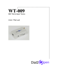
WT-009 “Dial to Open” Device Diagram
2
WT-009 USER MANUAL
Contents
1. Introduction..........................................................................................…....4
2. Advantages of WT-009 “Dial to Open” Device……………………………………………………….…4
3. WT-009 “Dial to Open” Device Operating Instruction………………………………………………5
4. WT-009 Programming Instructions….….……………………………………………………………………6
5. Additional Input & Output Programming Instructions………………………………………………8
5.1. Input Settings…………………………………………………………………………………………………….9
5.1.1. Programming the Administrator Number……………………………………………….9
5.1.2. Setting the Recipient that will Receive Alert Message…………………………10
5.1.3. Editing the Alert Message………………………………………………………………………11
5.1.4. Turn On the Function of Input………………………………………………………………12
5.1.5. Setting the Counter Alert Value for Input…………………………………………….12
5.1.6. Setting the Feature for Input………………………………………………………………..12
5.1.7. Reading the Total Increment Counter Value………………………………………..14
5.1.8. Reading the Sub Increment Counter Value………………………………………….14
5.1.9. Reset the Total Counter Value………………………………………………………………14
5.2. Output Settings……………………………………………………………………………………………….15
5.2.1. Activate the Output Relay to Stay On for a Specific Time…………………..15
5.2.2. Activate the Output Relay to Stay On…………………………………………………..16
5.2.3. Setting the Output Relay 2 to Supply Voltage or use Dry Contact……..16
5.3. Reset the WT-009 (Method 1)………….…………………………………………………………….17
5.4. Reset the WT-009 (Method 2)………………………………………………………………………..18
5.5. Auto Restart System……………………………………………………………………………………….18
6. Most common problems and solutions……………………………………………………………………19
3
WT-009 USER MANUAL
1. Introduction
“Dial to open” Device is an electronic board manufactured by Witura Corporation Sdn
Bhd that links to a SIMCOM 300 GSM module, supplied with it.
The purpose of this device is to be installed in parallel of the low voltage opening
button of an electric gate to enable it to be opened by means of a GSM phone.
It has a relay whose contact has to be connected in parallel with the button which
opens the gate. It has a White List of numbers who are enabled to open the gate, up
to 99.
When the “Dial to Open” Device receives a call, it will check to see if the calling
number is in the list. If it is in the list it will reject the call (so there will be no charge
– at least with today’s charging procedures) and click the relay momentarily.
2. Advantages of WT-009 “Dial to Open” Device
1) Safe – nobody can clone your phone as easily as they can do with a standard
remote control
2) Flexible – you can add or remove anybody number in a minute with an SMS
3) Cheap – you don’t need to buy a remote control for each member of your
family
4) Convenient – no matter if you change car, or if you have different gates to
open. Your phone will always be with you all the times your remote controls
were somewhere else!
4
WT-009 USER MANUAL
3. WT-009 “Dial to Open” Device Operating Instructions
Installation
To install the “Dial to Open” Device you need to connect the 2 wires of the relay
contact in parallel with the gate opening button. The relay contact can stand 48V 1A
maximum, this is enough for its operation but don’t try to switch higher voltages or
currents.
You also need to provide the power by means of 12 to 24 VAC or 12 to 24 VDC. The
power supply must be able to supply 2.4 Amps. DO NOT USE A GATE CONTROL PANEL
AS THE POWER SUPPLY. Don’t use telephone battery chargers! Most of them rely on
the phone battery and are unable to supply the power needed.
You should install the WT-009 “Dial to Open” Device in a place where there is GSM
signal coming from the operator you want to use. Check it with a phone before
proceeding with the installation. If you need to install the device in a place with little
signal, you may consider using an external antenna that we may supply as an option
to be purchased separately with 5m cable.
You should then insert the SIM of the operator you want to use and program in the
White List the numbers enabled to open the gate using the command WHL.
Note: You must remove the PIN request from the SIM before inserting it in
the unit, otherwise the device will not work. In order to do so, insert the SIM in a
phone and disable the PIN request (usually there is a security menu that enables you
to do so). If you don’t do it, and switch-on the unit more than 3 times you will have
to reset the PIN using the PUK!!
5
WT-009 USER MANUAL
4. WT-009 Programming Instructions
You can program the WT-009 with SMS commands using your phone. It is safe to do
so because in addition to the fact that other people may not know the number of the
SIM inserted in it, we also use a Password that makes it impossible for anybody, who
doesn’t know it, to access the system by chance.
Remember that commands must be CAPITAL LETTERS. It is PWD not pwd, CAP not
Cap etc.
Don’t add spaces or any other character.
Attention: Please program the WT-009 unit systematically begin with programming the white
list first.
The 2 SMS commands that you will certainly use in the “Dial to Open” Device are the
following:
#PWD: Password
#WHL: White List (add or remove numbers)
You could also use the following, though not necessarily:
#ACM: Access Mode
#CAP: Change password
#GOT: Gate pulse time
#CSQ: Check Signal Quality
Once you issue a command with an SMS, you will receive a confirmation SMS.
#PWD
Password. This command must always come first. Use 6 digits as a password.
The standard default one, when the device comes from the factory, is 123456.
We suggest that you change it, using the #CAP command.
In all the following examples we will use 123456 as an example of password.
#WHL
White List. This is the command that you will use most. It is used to add or remove
numbers that are enabled to open the gate into the White List. You can add up to 99
numbers in the list. Every position must be indicated in the command and we advise
you to keep a list written somewhere to know which numbers are in and in which
position.
6
WT-009 USER MANUAL
•
To add a number, the syntax of the command is the following:
#PWD123456#WHL01=3593334444
Where 01 is the position in the list and 3593334444 is the number enabled.
Please note that it is possible to program up to a maximum of 10 digits for a
number. If it has more digits you should use the rightmost ones. For example, if
your number is 33446665555 you should program 3446665555.
If your number appears as +393489999888 you should not program the country
code (+39). If your number has only 9 digits or less, it is not a problem. The
important thing is that you don’t exceed 10 digits.
•
To check which is the number in a place of the list:
#PWD123456#WHL01?
Example of Returned Message
WHL01:
3446665555
•
To erase a number:
#PWD123456#WHL01D
Returned Message
WHL01-OK
•
To erase all number
#PWD123456#WHL99D
Returned Message
DELALL-OK
Note: To erase the number stored in place 99 in the list only, you would send the
command #PWD123456#WHL99=0000000000
#ACM
Access Mode. This command allows you to open only to people that are in the white
list or to anybody calling the SIM number.
•
#PWD123456#ACM0 (it is a zero)
Warning! With the above command you allow free access to anybody calling!!
Returned Message
7
WT-009 USER MANUAL
ACM-OFF
•
#PWD123456#ACM2
With the above command, you allow only people that are in the white list
and administrator list. This is the standard and recommended option.
Returned Message
ACM-ON
#CAP
Change Password. Use this command to change the password with a new one that
you will chose for your device (don’t forget it or you will have to send the unit back
to us to reset it, and this has a cost!)
The #CAP command must be issued 2 times to be sure you don’t digit a wrong one.
Of course it must be preceded by the old password.
For example, to change the password 123456 into the new password 333444 you
need to send the following SMS:
•
#PWD123456#CAP333444#CAP333444
Example of Returned Message
CAP:
333444
#GOT
Gate pulse time. This command is useful in case you need to keep the button
pressed longer. The standard time is 1 second (Maximum 99 seconds). You can
change it with the GOT command.
The syntax of the command is the following:
•
#PWD123456#GOT02
With the above command, the opening time has been set to 2 seconds.
Returned Message
GOT:
02
#CSQ
Check GSM signal quality. This command is useful to see what is the GSM network
signal level your “Dial to Open” Device is receiving.
8
WT-009 USER MANUAL
If you send the command: #PWD123456#CSQ?
You should receive an SMS with signal quality in range 0 to 31 (if it is 0 we doubt it
will ever answer…). You should have a signal above 12 to be sure of being able to
open the gate in any condition. Better if above 16. You should add an external
antenna if this is not the case, or eventually even change operator with another that
serves your area better.
Example of Returned Message
CSQ=<21>
5. Additional Input & Output Programming Instructions
The WT-009 also comes with additional 1 Input and 1 Output. The output is
connected to an on-board relay which can be activated by sending an SMS command.
The Input can be used to generate alarms when triggered. It also can be
programmed to count the input active pulses up to 1ms fast or activate the output
relay.
Note: When used as counters input work only in ACTIVE HIGH mode, they count
ONLY High Going Pulses.
5.1) Input Settings
One of the most important functions is to receive alarms. In order to do this
properly, you must program the administrator numbers, turn on the function
of the input and tell the WT-009 which are the recipient numbers and who
should receive the alert message for the particular input.
5.1.1) Programming the Administrator Number
The 8 administrator numbers can be programmed with a text command via SMS.
Text Command:
#TEL[N]=XXXXXXXXXX
N stands for administrator number 1 – 8 (position)
XXXXXXXXXX stands for the phone number you want to program as administrator.
9
WT-009 USER MANUAL
•
To add a number, the syntax of the command is the following:
#PWD123456#TEL1=3593334444
Example of Returned Message
TEL1:
3593334444
Please note that it is possible to program up to a maximum of 16 digits for a number.
•
To check all the administrator number in the list:
#PWD123456#TEL?
Example of Returned Message
TEL1:
3593334444
TEL2:
0000000000
TEL3:
0000000000
TEL4:
0000000000
TEL5:
0000000000
TEL6:
0000000000
TEL7:
0000000000
TEL8:
0000000000
Note: Programming the administrator numbers is necessary in order to operate all the below
functions and to receive text alerts when the relays activated.
5.1.2) Setting the Recipient that will Receive Alert Message
The unit can only send text alerts to 1 or all 8 of the programmed administrator’s
mobile phone numbers and this function can be changed at any time by sending the
following commands by SMS message to the unit.
Text Command:
10
WT-009 USER MANUAL
#RERN=XXXXXXXX
XXXXXXXX stands for 8 digits value: ON (1) or OFF (0) for the 8 administrators
For example, if we assume only administrators 1, 2, 3, and 4 are to receive text
alerts you would send the following SMS message to the unit.
•
#PWD123456#RERN=11110000
Example of Returned Message
RERN:
11110000
Note: You can only put 1 in the first 4 digits of the text command if there are only phone
numbers stored in #TEL1, #TEL2, #TEL3 and #TEL4. The rest should be 0.
•
To check the setting of which recipient will receive alert messages
#PWD123456#RER?
Example of Returned Message
RERN:
11110000
5.1.3) Editing the Input Alert Message
The Input Alert Message can be edited and programmed up to 100 characters long.
You can change the displayed text by sending the following commands by SMS
message to the unit. Note: Only support normal abc/ABC English text, no special characters.
Text Command:
#STR=XXXXX…
XXXXX stands for the display text that you want to program
For example, if you want the alert message to display “Garage Opened!” when
received a text alert; you would send the following SMS message to the unit.
•
#PWD123456#STR=Garage Opened!
Example of Returned Message
String:
Garage Opened!
11
WT-009 USER MANUAL
5.1.4) Turn On the Function of Input
To turn on the function of input, you can send the following commands by SMS
message to the unit.
Text Command:
#CTR=X
X stands for ON (1) or OFF (0) value
•
To turn on the input, the syntax of the command is the following:
#PWD123456#CTR=1
Returned Message
CTR=<1>
5.1.5) Setting the Counter Alert Value for Input
An alert message will be sent when the increment of alarm counter reaches the alert
value (Default: 500). It is possible to set the alert value up to maximum value of
65535 times. To set the counter alert value of input, you can send the following
commands by SMS message to the unit.
Text Command:
#COA=XXXXX
XXXXX stands for 5 digits value: The number of times
For example, assume you want it sends a counter alert message each time the input
has triggered for 5 times, you would send the following SMS message to the unit.
•
#PWD123456#COA=00005
Example of Returned Message
COA=00005
5.1.6) Setting the Feature of Input
This input can be programmed to behave differently, it can count the input active
high pulses, generate an alarm message or activate relay. To program the input, you
can send the following commands by SMS message to the unit.
12
WT-009 USER MANUAL
Text Command:
#CTC=F
F stands for input function 1 - 5
Function Descriptions
Function 1:
-
Function as counter
-
Sends a counter alert message once alarm counter reaches the alert value
Function 2:
-
Function as counter
-
Activate the output relay 2 to stay on
-
Sends a counter alert message once alarm counter reaches the alert value
Function 3:
-
Function as counter
-
Activate the output relay 2 to stay on
-
Sends an alert message once triggered
-
Sends a counter alert message once alarm counter reaches the alert value
Function 4:
-
Function as counter
-
Activate the output relay 2 for 1 second
-
Sends a counter alert message once alarm counter reaches the alert value
Function 5:
-
Sends an alert message once triggered
For example, assume you want it to send an alert message each time the input
triggered, you would send the following SMS message to the unit.
•
#PWD123456#CTC=5
Example of Returned Message
CTC=<5>
13
WT-009 USER MANUAL
5.1.7) Reading the Total Increment Counter Value
To read the total increment counter value, you can send the following SMS message
to the unit.
Text Command:
#COU?
•
The syntax of the command is the following:
#PWD123456#COU?
You will receive the total increment value from the unit by SMS.
Example of Returned Message
INC:
00015
5.1.8) Reading the Sub Increment Counter Value
To read the sub increment counter value, you can send the following SMS message
to the unit.
Text Command:
#COT?
•
The syntax of the command is the following:
#PWD123456#COT?
You will receive the sub increment value from the unit by SMS.
Example of Returned Message
COT:
00015
Note: The sub increment counter value will be reset automatically each time the alarm
counter reached the alert value.
5.1.9) Reset the Total Counter Value
To reset the total counter value, you can send the following SMS message to the unit.
Text Command:
#CLA
14
WT-009 USER MANUAL
•
The syntax of the command is the following:
#PWD123456#CLA
Example of Returned Message
RECO-OK
5.2) Output Settings
5.2.1) Activate the Output Relay to Stay On for a Specific Time
To activate the output relay, you can send a text command via SMS specifying the
number of seconds the output should stay on to the unit. It is possible to set up to
maximum of 65,535 seconds
Text Command:
#RLY[N]=XXXXX
N stands for number 1 or 2 of Output
XXXXX stands for 5 digits value: The number of seconds
For example, assume you want to turn on the output relay number 2 for 1 hour, you
would send the following SMS message to the unit.
•
#PWD123456#RLY2=03600
Example of Returned Message
RLY2=03600
•
To check the status of output relay
#PWD123456#RLY?
Example of Returned Message
RLY1:
03580
RLY2:
00000
Note: The reply message will be send to the recipients (The Administrators) only when the
relay has turned on/off. This is to notify the administrators when someone outside the list
activates the relays.
15
WT-009 USER MANUAL
5.2.2) Activate the Output Relay to Stay On
To activate the output relay to stay on, you can send the following commands by
SMS message to the unit.
Text Command:
#RLOP[N]=X
N stands for number 1 or 2 of Output
X stands for ON (1) or OFF (0) value
•
To activate the output relay number 2 to stay on indefinitely, the syntax of
the command is the following:
#PWD123456#RLOP2=1
Returned Message
RLOP2-ON
Note: The reply message will be send to the recipients (The Administrators) only when the
relay has turned on/off. This is to notify the administrators when someone outside the list
activates the relays.
5.2.3) Setting the Output Relay 2 to Supply Voltage or use Dry Contact when Activated
To set the output relay 2 to supply DC voltage when activated, please adjust the
jumper according to the below diagram
16
WT-009 USER MANUAL
Note: Relay 2 will supply DC voltage only according to the output DC voltage of adapter used.
When 24VAC adapter is used, the voltage supplied would be 33VDC.
To set the output relay 2 to use dry contact (Default) when activated, please adjust
the jumper according to the below diagram
5.3) Reset the WT-009 (Method 1)
To reset the unit, you can send the following SMS command to the unit.
Text Command:
*REST#XXXXXX
XXXXXX stands for 6 digits password based on #PWD and it can be changed
anytime with #CAP command
Example:
•
To reset the unit (with default password 123456), the syntax of the command
is the following:
*REST#123456
Returned Message
REST-OK
17
WT-009 USER MANUAL
5.4) Reset the WT-009 (Method 2)
To reset the unit using this method, you will need to supply a DC 12 – 40V at the
input and turn on the unit. The network LED will stay lit for 1-3 seconds and off.
Once the network LED stops lit, the DC power supply at the input needs to
disconnect immediately in order to successfully reset the unit.
5.5) Auto Restart System
The WT-009 can continuously monitor the system status of its own. When there is a
problem with system operation or the module is not working properly, it will restart
the system automatically to avoid the unit stopped working. After 15 seconds of
system failure, it will restart the system for 30 seconds and then the system will be
ready to use.
18
WT-009 USER MANUAL
Some phones cannot open the gate:
Verify that they send the caller ID when calling another phone. Check that the
you
see in the
other
phone is what you have programmed in the “Dial to
6. Most number
common
problems
and
solutions
Open” Device
I have inserted the SIM but the unit doesn’t work:
Check to have removed the PIN request from the SIM. If you didn’t do it and you
have switched-on the unit more than 3 times, you may need to use the PUK. Check
with SIM instructions for details
I have checked in all possible ways but still the unit doesn’t work:
Try to change operator.
Is it possible to open to anybody?
Yes, you can do it using the #ACM command.
Please be aware that some networks will disable a SIM if it is not used to make a
call or send a text message over a period of time, please check with your network
19