1
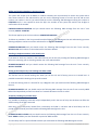
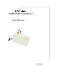
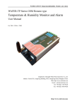
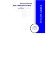
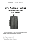
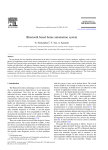
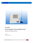
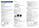
Product Model: GRC-010 V2.0
GRC-010 GSM Remote Control
GRC‐010 GSM Remote Control Electric Gate
le
p
m
Co
Introduction n
o
i
x
Existing Gate Controller The GRC‐010 has been designed to operate Gates and other electrical devices using your existing Mobile Phone or Land Line and also eliminating the problems that occur with low range wireless remote controls as this system has no range barriers. This system allows the administrator or user to operate two separate relays. One using caller ID to active relay one automatically with a voice call or alternately it is possible to SMS the system to activate Relay 2 to perform another function. Another feature is an Alarm Input function which has the ability to send up to 8 separate SMS alerts in the event of an incident such as a power failure or an alarm being activated and a personal customized message can be programmed into the system. The system comes with an in‐build power supply and external antenna and only requires a valid SIM Card n
o
i
x
le
p
m
Co
GRC010
GSM Remot
eCont
r
ol
1 | P a g e
User Manual V1.3 Updated Nov 2013
Power Supply The Power supply of 12 Volt DC supply capable of providing 1 Amp current and never use the power supply from Gate control panels as they may show a 12 Volt reading and initially Log on to the system, but can draw higher current when Network signal strengths drop and not only log off, but may also blow the fuses on the Gate control board as GSM Modems will draw excessive currents whilst searching for the network connections. Low Voltage 12 Volt Gate systems can in most cases be connected directly as they are normally connected to a permanent backup system being able to support the current required. n
o
i
x
le
p
m
Co
SIM Card The system will accept any Universal Network SIM Card and it is essential that you remove any Pin Code requests from the SIM Card which can be done by placing the SIM Card in an unlocked Mobile Phone and using the features on most Mobile Phones to disable the Pin Code request as if the Pin Request is enabled the system will not log on to the network and the unit will refuse to be programmed. In addition it is essential you also disable the Voice Mail function which can be in some case done again by placing the SIM Card in an unlocked Mobile Phone and contacting your service provider to remove this function and insure the SIM Card does not accept or store any incoming voice messages. Mobile Phone Credit It is also essential that the SIM Card is retained with enough credit at all times so as to be able to receive the SMS text alerts when making any changes to the system remotely even though the system will continue to perform and make the changes required although you just will not receive the confirmation text messages back from the unit. In addition the system will still operate by calling the unit and opening the Gate as there is no connection charge for using this function Installing the SIM Card and booting up the system To Install the SIM Card you will need use a small pointed screw driver and depress the small yellow button beside the SIM Card tray as labeled SIM Card and the SIM Card tray will pop out and you can remove the tray and locate the SIM Card in the holder and gently side the SIM Card tray back into its receiver slot. Don’t ever force the SIM Card tray or attempt to remove it out with a screw driver by levering it as you will only damage the unit and render it useless. The Red power light will come on and the Green network light will oscillate infrequently until it locates the network and once it has secured itself on the network the green Network light will flash every 4 seconds constantly. n
o
i
x
If this does not happen after say one minute the system has not logged on and you will need to check the SIM Card is positioned correctly and that the antennae is connected or it may be the signal area is too low. le
p
m
Co
Once the system is connected to the network it is now possible to actually Change the Password if required and then check the Signal Strength at the location using SMS Messaging. 2 | P a g e
User Manual V1.3 Updated Nov 2013
n
o
i
x
le
p
m
Co
Password All SMS Commands are sent to the unit with a Password prefix which is factory set as default of the password digits of 123456 #PWD123456 and this format is the prefix to any commands sent to the unit and all of the commands are always sent in CAPITAL letters with no spaces or symbols! It is possible to change this password if required and to change this to 654321 you would send the unit the following SMS Message. #PWD123456#CAP654321#CAP654321 and this is sent in this format as confirmation and you should receive the following SMS message from the unit if sent correctly. CAP: 654321 and the new password is now 654321 Checking the Signal Strength The next thing you may wish to do is check the actually signal Strength at the location and to do this you would send the unit the following SMS Message. #PWD654321#CSQ? and you should receive the following similar SMS message from the unit if sent correctly. CSQ <12 > This indicates the signal strength of <12 > from a range of between < 1 > and < 31 > and it is advised if you are registering a signal strength any lower then < 5 > or < 6 > it would be advised to add an additional external antennae to improve the signal strength or change the Network. Security Mode The system can store up to 99 numbers that are the numbers that would be authorized to access the system by calling the unit and this mode of security can be tuned on or off to suit the customer requirements. These 2 modes are either “Open Mode” in which any person calling the unit can access the system or “Security Mode” which restricts access to only the numbers programmed into the system. The system comes in “Open Mode” as factory default to allow the system to be set up and programmed prior switching the system to “Security Mode” and to change the mode is done via SMS Messaging. To switch the mode of operation to “Security Mode” you would send the unit the following SMS Message #PWD654321#ACM2 and you should receive the following SMS message back from the unit if sent correctly ACM‐ON n
o
i
x
le
p
m
To switch the mode of operation back to “Open Mode” you would send the unit the following SMS Message #PWD654321#ACM0 and you should receive the following SMS message back from the unit if sent correctly ACM‐OFF Co
3 | P a g e
User Manual V1.3 Updated Nov 2013
Adding and Deleting Numbers in the Security List The system will accept up to 99 Mobile or Landline numbers that are authorized to access the system and to store these numbers in the authorized list you can use the following format as from 01 up to 99 and to store number one number in the list you would send the unit the following SMS Message assuming the number as 023456789 and it is not required to enter the (0) in the number as the system will read the last 8 digits as confirmation of the number. PWD654321#WHL01=23456789 and you should receive the following SMS message from the unit if sent correctly. WHL01: 23456789 n
o
i
x
le
p
m
This format applies up to the last number as #PWD654321#WHL99= Co
To delete any numbers in the list you would send the following SMS Message to the unit and assuming you were deleting telephone number one of the authorized list as WHLO1=23456789 #PWD654321#WHL01D and you should receive the following SMS message from the unit if sent correctly. WHL01D <OK> and number 1in the authorized list has been deleted. Checking a telephone Number in the Security List If you want to check any number in the authorized list you can do so by sending the following SMS Message to the unit as assuming you are checking number one in the authorized list. #PWD654321#WHL01? and you should receive the following SMS message from the unit if sent correctly. WHL01: 23456789 Setting up the Output relay one Latching time when called This function sets the actual latching time when you call the unit and is factory pre‐set at 1 second but it is possible to extend this latching time up to 60 seconds To reset the latching time to 5 seconds for say a Magnetic Lock you would send the following SMS Message to the unit. #PWD654321#GOT05 and you should receive the following SMS message from the unit if sent correctly. GOT: 05 and the Output Relay one will now latch for 5 seconds whenever the unit is called Temporary latching any or both relays It is possible to temporary latch both relays independently and in the case of relay one this does not affect the default setting of the GOT command. n
o
i
x
le
p
m
Both relays can be temporary latched from 1 second up to 65,000 i.e. 18 hours and to latch Relay one for a period of 3600 seconds you would send the following SMS message to the unit. Co
#PWD654321#RLY1=03600 and you should receive the following SMS message from the unit if sent correctly. RLY1: 03600 and Relay one has latched for a period of 3600 seconds. To Latch Relay two for a period of 3600 seconds you would send the following SMS Message to the unit. 4 | P a g e
User Manual V1.3 Updated Nov 2013
#PWD654321#RLY2=03600 and you should receive the following SMS message from the unit if sent correctly. RLY2:03600 and Relay one has latched for a period of 3600 seconds. n
o
i
x
Latching the relays permanently On and Off le
p
m
It is possible to latch both relays either On or Off permanently and this will not affect the default setting of Relay one but the command to latch for the 1 second will obviously be ignored if the Relay has been programmed to be permanently switched On. Co
To Latch Relay 1 On permanently you would send the following the SMS Message to the unit. #PWD654321#RLOP1=1 and you should receive the following SMS message from the unit if sent correctly. RLOP1: ON and Relay one has been latched permanently On. To Latch Relay 1 Off permanently you would send the following the SMS Message to the unit. #PWD654321#RLOP1=0 and you should receive the following SMS message from the unit if sent correctly. RLOP1: OFF and Relay one has been latched permanently Off. The same format would be used for permanently latching Relay 2 On and off using the commands as #RLOP2=1 and #RLOP2=0 Receiving SMS Text alerts and messages from the unit It is possible to receive SMS alert messages to confirm both relay latching has been implemented and also when the Relays Latch off. In addition it is possible to receive SMS text alerts when the Input is activated as described in the Alarm Functions section. The system can send these SMS text alerts to 8 separate Mobile phones in the sequence they were programmed into the system and referred to as administrator numbers 1‐8 and can also be toggled on or off remotely via a Matrix as explained in the Administrators Matrix section. Programming in the Administrator Numbers The Administrator numbers are programmed into the system using the command #TEL1 through to #TEL8 and to program in #TEL1 you would send the following SMS Message to the unit. #PWD654321#TEL1=07847070001 and you should receive the following SMS message from the unit if sent correctly. TEL1: 07847070001 n
o
i
x
When programming the administrator numbers always enter the full telephone number and if you wish to receive SMS alerts whilst abroad always put the complete number in including the International code as this is the number the system is programmed to transmit the SMS text alerts to. le
p
m
Co
The remaining administrator numbers are programmed in the same format up to #TEL08 5 | P a g e
User Manual V1.3 Updated Nov 2013
Administrators Matrix Once you have programmed in the administrators numbers it is now possible to also now program a matrix of who should receive the SMS text alerts and confirmation messages. n
o
i
x
le
p
m
The system is pre‐set as factory default to send #TEL1 SMS text alerts and messages once that number has been entered and confirmed in the #TEL1 and the #CTR=1 alarm function turned On. Co
The Matrix is programmed using the #RERN command which can toggle the list of numbers On or Off based on using the digit 1 as On and 0 as Off as follows. The factory default has set up the #RERN as #RERN=10000000 which indicates the first administrator number in the list will receive the SMS text alerts and messages and the remaining seven administrators will not receive any SMS text alerts or messages. To change the Matrix of persons who will receive the SMS alerts or messages you would simply use this format and to assume we want only administrator 1 4 and 6 to receive the SMS alerts and messages we would send the following SMS message to the unit. #PWD654321#RERN=10010100 and you should receive the following SMS message from the unit if sent correctly. RERN=10010100 and only the administrators 1 4 and 6 will receive the SMS text alerts and messages. To change the matrix you would just over write the existing matrix by sending anther SMS message to the unit and if you want to send more than one message to one off the Administrators you would simply enter that administrator in the #TEL list the number of times you want them to receive the SMS text alerts and messages. Setting up the Alarm Input Message when activated The system has an alarm Input that will trigger a customized SMS text alert to the administrators as recorded in the #TEL list and activated in the Matrix to receive the SMS text alerts.(and you also need to have the #CTR=1 alarm function turned On) This alarm is activated by applying a 12 Volt DC supply to the alarm Input connection for a period of 5 seconds and to customize the SMS Message you would send the following SMS Message to the unit assuming the required message is to be “Gate Forced” #PWD654321#STR=”Gate Forced” and you should receive the following SMS message from the unit if sent correctly. STR: “Gate Forced” and this SMS Message will now be sent to the administrators from the #TEL list that are programmed in the Matrix to receive the SMS text alerts. Setting up the Alarm Input Message when De‐activated It is also possible to Program an alarm message that is sent when the alarm Input returns to normal status or Alarm Power is removed and to set the following message as “Gate locked again” you would send the following message to the unit. n
o
i
x
le
p
m
#PWD654321#STO=”Gate locked again” and you should receive the following SMS message from the unit if sent correctly. STR: “Gate locked again” and this SMS Message will now be sent to the administrators from the #TEL list that are programmed in the Matrix to receive the SMS text alerts. Co
6 | P a g e
User Manual V1.3 Updated Nov 2013
Setting up the alarm status Modes “Power applied” and “Normal status” The system allows you to send just an alarm message when the Power is applied and no alert messages when the Power returned to normal and this is done by sending the following message to the unit #PWD65432#CTC=5 and you should receive the following SMS message from the unit if sent correctly. #CTC <5> and you will only receive the message as programmed in as with the #STR “Gate Unlocked” when the Voltage is applied to the Input alarm connection. To receive the #STR alert message when the Voltage is applied and also to receive the #STO message when the input Voltage is removed you would send the following SMS message to the unit. #PWD654321#CTC=6 and you should receive the following SMS message from the unit if sent correctly. CTC <6> and the administrators programmed to receive text alerts will receive both messages. n
o
i
x
le
p
m
Co
To receive either Alert messages one or the other of the #CTC=5 or #CTC=6 have to be programmed into the system otherwise the alert messages will not be sent and also the following alarm function must be turned on. Turning the Alarm function On and Off The alarm function can also be turned on or off if required and to turn this function on you would send the following SMS Message to the unit. #PWD654321#CTR=1 and you should receive the following SMS message from the unit if sent correctly. CTR: ON and the Alarm Function has been turned on. To turn this function back off you would use the command #CTR=0 and you should receive the following SMS message from the unit if sent correctly. CTR: OFF and the alarm function has been turned off. Resetting the System The system can be reset to factory default by sending the following SMS Message to the unit. *REST#654321 and you should receive the following SMS message from the unit if sent correctly. REST‐OK and
the system has now been restored to factory default. The password is now restored to 123456 the default latching time for Relay one is 1 Second and the system memory is now blank! And will require reprogramming from the beginning. So please note this when sending the *REST# command. 7 | P a g e
User Manual V1.3 Updated Nov 2013
Schematic and Wiring Diagram n
o
i
x
le
p
m
Co
LIST OF SMS COMMANDS
8 | P a g e
#PWD123456
FACTORY DEFAULT PASSWORD
#CAP
CHANGE PASSWORD
#CSQ?
CHECK SIGNAL STRENGTH
#WHL
ADD USER NUMBERS
#WHL D
DELETE USER NUMBERS 1‐99
#WHL99D
DELETE ALL USER NUMBERS
#GOT 01‐60
CHANGE DEFAULT LATCHING TIME
#RLY1 #RLY2
TEMPORARY LATCHING
#RLOP1 #RLOP2
PERMINANT LATCHING
#TEL 01‐08
ADD ADMINISTRATORS
#RERN
SET ADMINISTRATOR MATRIX
#STR
SET ALARM MESSAGE Voltage High
#STO SET ALARM MESSAGE Voltage Low
#CTC=5
TURN ALARM MESSAGE ON #STR
#CTC=6
TURN ALARM MESSAGES ON #STR #STO
#CTR1 #CTR0 TURN ALARM FUNCTION ON‐OFF
*REST#
RESET UNIT
User Manual V1.3 Updated Nov 2013