1
MLR: Electrical Study Guide
Table of Contents
MLR: Electrical Study Guide .......................................................................................................................... 1
UNIT 1: ELECTRICAL THEORY .................................................................................................................... 2
Chapter 1: Electromagnetism............................................................................................................... 2
Chapter 2: Magnetic Components ....................................................................................................... 6
Chapter 3: Electrical Properties............................................................................................................ 9
UNIT 2: ELECTRICAL DEVICES AND CIRCUITS .......................................................................................... 14
Chapter 1: Circuit Components and Symbols..................................................................................... 14
Chapter 2: Ohm's Law and Circuits .................................................................................................... 19
Chapter 3: Digital Multimeters........................................................................................................... 24
Chapter 5: Testing Series and Parallel Circuits ................................................................................... 32
Chapter 6: Diagnosing Using Wiring Diagrams .................................................................................. 36
Unit 3: AUTOMOTIVE BATTERIES ........................................................................................................... 45
Chapter 1: Batteries Overview ........................................................................................................... 45
Chapter 2: Power Loss ........................................................................................................................ 51
Chapter 3: Charging and Replacement .............................................................................................. 60
Unit 4: STARTING SYSTEMS .................................................................................................................... 66
Chapter 1: Starting System Components ........................................................................................... 66
Chapter 2: Starting System Diagnosis and Service ............................................................................. 71
Unit 5: CHARGING SYSTEMS ................................................................................................................... 77
Chapter 1: Charging System Components ......................................................................................... 77
Chapter 2: Charging System Diagnosis and Service ........................................................................... 84
©2013 Melior, Inc.
MLR: Electrical Study Guide
©2013 Melior, Inc.
UNIT 1: ELECTRICAL THEORY
Chapter 1: Electromagnetism
Safety Warnings and Cautions
Safety in the workplace is of great concern to all of us. The Concepts you learn in each of the modules of
this online training program will be applied using real test equipment on live electrical circuits in related
projects. It is imperative that you understand that electrical safety is extremely important. The words
“caution,” “warning” and “danger” are related and mean this: If you do not heed the safety message,
you can damage components, equipment, or injure or kill yourself or someone else. The last thing you
want to do is become a statistic. Every year, people are injured or killed and property is damaged due to
not following electrical safety rules and common sense. Do yourself and others a favor. Pay attention
and use safe practices.
Warning! To avoid possible personal injury:
Always follow all general safety guidelines for servicing motor vehicles with regards to electrical
connections, flammable or corrosive materials, adequate ventilation, jacking and supporting,
working around hot or moving parts, proper use of parking brake, gear selector, wheel blocks, and
disabling fuel or ignition systems. Refer to the equipment User's Manual and vehicle Service
Manual for the operation you are performing.
When making electrical measurements, never exceed voltage or current limits as indicated for the
equipment.
Use extreme caution when working with circuits that have greater than 60 volts DC or 24 volts AC.
Do not operate damaged equipment.
Automotive batteries can explode, and have enough power to arc weld. Always respect the power
of a battery, even a “dead” battery. The sulfuric acid in electrolyte is extremely corrosive, and can
cause severe chemical burns to the skin and eyes. It will also damage painted surfaces and many
other materials, including clothing. Always wear approved safety glasses when working around
batteries and the use of rubber gloves is recommended when working with electrolyte. Batteries
release hydrogen and oxygen gasses. When a battery explodes, it can rupture the case and spray
acid in all directions. Avoid creating sparks around a battery.
The ground terminal of a battery should always be disconnected first and reconnected last.
Connect battery chargers to a battery before plugging in the charger.
When jump-starting a vehicle, follow the proper procedure. Do not connect the jumper cable to the
negative battery terminal of the vehicle you are jump-starting.
Do not attempt to charge, jump-start, or load test a battery with a broken or loose post, a cracked
case, or one in which the electrolyte is frozen.
Page 2 of 88
MLR: Electrical Study Guide
©2013 Melior, Inc.
Never hammer on a battery terminal or cable end, or attempt to remove a cable by prying. To
avoid damage to the battery or terminals, and possible personal injury, use a clamp-spreading tool if
the clamp doesn’t seat at the bottom of the post, and use a cable clamp puller to remove stubborn
clamps. Avoid contact with the white, flaky or powdery corrosion that builds up around battery
terminals and trays. This substance is sulfate and/or sulfide; it is corrosive and can cause chemical
burns.
Accidental shorting of the positive battery terminal or any system voltage source to ground with a
tool or metal object can cause severe burns. Metal jewelry can be heated to its melting point in
seconds. Even a brief short of this nature can damage the PCM and other electronic components.
You should know the locations of fire extinguishers and the first aid kit. First aid kits should contain a
bottle of sterile, acid-neutralizing eyewash. Larger facilities often have an emergency shower and
eyewash station located in the battery storage and service area.
What is Electricity?
In order to properly diagnose and repair automotive electrical systems, a technician must first have an
understanding of how those systems operate. In this section, we will look at electrical fundamentals and
how they determine the construction and application of all automotive circuits.
For the purposes of an automotive technician, electricity is best defined as: “The movement of
electrons through a conductor having the ability to do work". In order to understand how these
electrons move, one must understand how matter and energy interact at an atomic level.
Atoms
We have all studied the atom and how it is composed of a nucleus including Protons (which have a
positive charge) and Neutrons (which have no charge) with Electrons revolving around it (which have a
negative charge). We also know that each type of atom has a different number of electrons around its
perimeter.
Page 3 of 88
MLR: Electrical Study Guide
©2013 Melior, Inc.
Atomic Structure
The copper atom has 29 electrons around its
nucleus located in different layers or shells around
the nucleus, two in the first shell, eight in the
second and 18 in the third shell for a total of 28.
That leaves just one electron in the outer shell or
"Valence shell", and this single electron is the one
that does all of the electrical work. Atoms that have
one or two electrons in the valence shell are called
conductors. They include copper, gold, silver,
aluminum, nickel, zinc, and others. That is why they
are used to make wire.
Atom Info:
1 or 2 valence electrons are conductors
3, 4, or 5 valence electrons are semiconductors
6, 7, or 8 valence electrons are insulators
Valence Electrons:
Electrical force is applied to valence electrons, which
causes them to move through wires.
Atoms with a large number of electrons in the outer shell are called insulators and include rubber,
plastics, etc. Those atoms that have around four electrons in the valence shell are called
semiconductors. Semiconductors are used to make electronic components such as transistors, which
will be discussed in later modules. At this point you may be asking, "So what does this have to do with
electricity?" Very simple really…
Magnetism
Another electrical characteristic we'll use in a later
section is Magnetism. Magnetism, or Electromagnetism,
is also caused by the movement of electrons in a wire,
and is the property that makes generators, starters,
blower motors, EGR valves, and many other "actuators"
work.
Electromagnets:
An electromagnet is created when a
current is run through a wound wire.
Magnetism:
Magnetism is used to convert electrical
energy to mechanical energy or
mechanical energy to electrical energy.
Magnetism is used extensively in automotive applications
to convert electrical energy to mechanical energy, or
conversely, to change mechanical energy to electrical
energy. For instance, if we apply electrical current to certain devices we can create lateral (straight line)
motion such as in the starter solenoid (to engage the starter drive), or to open fuel injectors. Still other
components will use applied electricity to produce rotary (spinning) motion, as is the case with fuel
pumps and starter motors. Generators, however, use magnetism to change motion (belt driven) to
electrical output. In the automotive field there are two types of magnets used. They are:
Permanent magnets
Electromagnets
Permanent Magnets
We are all familiar with permanent magnets, those gray colored devices usually made in bar or
horseshoe shapes. It's likely most of us have a number of permanent magnets attached to our
refrigerators holding up out-of-date notes and drawings. In cars and trucks we will find permanent
magnets in Crank Position Sensors (distributor and distributorless types), Cam Position Sensors, ABS
sensors, some fuel pumps, Vehicle Speed sensors, and new style starters.
Page 4 of 88
MLR: Electrical Study Guide
©2013 Melior, Inc.
Electromagnets
Electromagnetism occurs when an electrical current is passed through a conductor and creates a
surrounding magnetic field.
Electromagnets usually consist of a wire wound around a metal core and powered by an electrical
source. Some students may have done an experiment in school where a wire was wrapped around a nail
with both wire ends attached to a battery to form an electromagnet. The device could then be used to
pick up paper clips.
Examples of electromagnetic automotive applications include starter solenoids and fuel injectors, as
mentioned earlier, as well as some EGR valves, relay contacts, transmission shift and pressure-control
solenoids, numerous vacuum control valves, blower motors, cooling fans, wiper motors, fuel pumps,
generators and, of course, old style starter motors.
Magnetic Fields
All magnets, whether permanent or electromagnet, have two poles: North and South. Like poles (N-N or
S-S) repel and unlike poles (N-S) attract.
Magnetic Field:
Automotive applications all operate by magnetic attraction
rather than magnetic repulsion. Between these two poles are
The stronger a magnet is, the
greater its "flux density".
invisible lines of force called the "flux lines" which make up the
magnetic field. A magnet with many flux lines (or high flux
density) is strong whereas a weak magnet has few flux lines or low "flux density".
Students may be familiar with instances where magnets have become
weak and caused operational problems such as a Crank Position Sensor
that causes the engine to cut out at higher rpm's or an ABS sensor that
drops to zero while the vehicle is still moving.
These problems are most often caused by a drop in the flux density of the
magnet itself but will not be seen in a resistance check of the wire
winding.
Magnetic Force
As electric current is passed through a wire, it creates magnetic lines of force around the wire. If that
wire is wound into a coil, it creates North and South Poles much like a permanent magnet except that it
can be turned on and off and made stronger or weaker. Because many metals are good magnetic
conductors, a core is often used in the center of the coil to enhance the strength of the electromagnet.
Most often, the core is part of the design like the plunger in a starter solenoid or the pintle in a fuel
injector. If a number of different magnetic devices were cut open, it would be apparent that the size of
the wire and the number of turns around the core are not the same. For various applications, designers
will change the wire size, the number of turns, the diameter of the coil, the length of the coil, and the
applied current to get just the right amount of magnetic force needed for a particular use.
Page 5 of 88
MLR: Electrical Study Guide
©2013 Melior, Inc.
Electromagnetic Induction
We have already seen that we can create a magnetic field
Electromagnetic Induction:
with an applied current, but now we will find that we can also
produce a current from a magnetic field. The process is called
Electromagnetic induction occurs
"electromagnetic induction". When a magnetic field and a
when a varying magnetic field creates
a current in a second winding.
wire are moved near each other, a voltage is produced in the
wire that causes a current to flow. This is called an "Induced
Voltage". As long as the movement continues, the current will continue, but if the motion stops, the
current will stop.
Applications of electromagnetic induction are typically in generators or alternators and in transformers
or ignition coils. Generators and alternators are designed similarly to motors in that they have a field
winding and an armature winding. How they differ in terms of their induction is this: generators have a
coil that turns and a magnetic field that is stationary whereas alternators have a magnetic field turning
inside of a stationary coil.
The amount of induced voltage (and therefore current) depends on several factors:
Strength of the magnetic field
Speed of motion between the coil and the magnetic field
Number of conductors in the coil
Chapter 2: Magnetic Components
Let's take a few moments to cover some specific applications of electromagnetism: relays, solenoids,
motors, and transformers.
Relays
A relay is an electromagnetic device that operates as an on-off
switch using a small coil current to control a larger contact
current. Inside a relay, there is a coil of wire and one or more sets
of contacts. Applying a small current to the coil creates a
magnetic field which "pulls in" the contact(s) and closes the
circuit sending the larger "controlled" current to the load device
(eg. fuel pump, ECM, etc.).
Page 6 of 88
MLR: Electrical Study Guide
©2013 Melior, Inc.
Because a relay uses a small amount of control circuit current to control the
flow of a larger current, it allows for the reduction of wire size throughout a
vehicle and a corresponding decrease in weight.
Primarily there are two types of relays on today’s vehicles. They are known as
Micro relays and Mini relays. They have normally 4 pins or 5 pins. But don’t let
the number of pins scare you. They all work in the same way!
Relay
The control side of the relay are pins 85 and 86. When
power and ground are applied to these two terminals an
electromagnetic field is created and a contact is pulled
down. When this contact is made it allows power waiting at
pin 30 to go though the contact and out pin 87 to its
destination. There are variables but remember that pins 85
and 86 are married as the control side and pins 87 and 30
are the load or work side of the relay. Pin 87A is normally
used to control another portion of a system such as the
park control in windshield wipers.
Solenoids (fuel injector)
A solenoid is an electromagnetic device that uses applied current to produce lateral
(back and forth) motion. Solenoids such as fuel injectors and transmission shift
valves have a movable metal core inside the coil. As current is applied to a coil, the
electromagnetic field it produces either pushes or pulls the core and opens or closes
a valve, or engages a starter drive. The terms relay and solenoid are sometimes
used interchangeably but in fact, they are two different things.
Motors
Electric motors also work on the principles of electromagnetism, but unlike
relays or solenoids, their function is to produce rotary (spinning) motion.
Motors have two primary components: an Armature or rotating element and
a stationary Field Coil. Motors can have permanent magnet armatures with
wound field coils, permanent magnet field coils with wound armatures, or
have both the armatures and field coils wound. Permanent magnet armature
motors are used in Alternating Current applications and are not common in
automotive applications.
In a DC electric motor, voltage is applied to the armature winding through a pair of carbon brushes and a
split ring called a commutator. The commutator has the effect of alternately changing the poles of the
armature coil from north to south and back again for each half revolution of the armature. For example,
let's assume that a point on the outer Field Coil has a north orientation. The half of the armature that
has a south polarity would be attracted to that point and would cause the unit to rotate as they pulled
closer. However, just as the two points align, the commutator switches the armature polarity and the
new south point is now on the opposite side of the armature winding which causes it to attract the
north point on the field coil and the rotation continues.
Page 7 of 88
MLR: Electrical Study Guide
©2013 Melior, Inc.
To build a simple motor, you need a loop
of wire/armature, two permanent magnets
used to form a north and south pole, a
commutator power source, and set of
brushes.
DC motors can rotate clockwise or
counter-clockwise depending on current
flow. This allows one DC motor to control
the up and down motion of the power
windows or back and forth motion of
power seats.
Transformers
Transformers are another type of device that works by
electromagnetic induction. A transformer is constructed
with two separate windings (a primary and a secondary)
wrapped around a common metal core. When alternating
current or pulsating DC current is applied to the primary
winding a voltage is created, or induced, into the
secondary winding.
Transformers are classified as either Stepup or Step-down. A Step-up transformer
will create a higher voltage in the
secondary winding while a Step-down will
cause a lower voltage. Your local electrical
sub-station has a series of Step-down
transformers to reduce the voltage before
it enters your house.
Page 8 of 88
Transformers:
Transformers use electromagnetic
induction to increase or decrease an
applied voltage or current.
MLR: Electrical Study Guide
©2013 Melior, Inc.
The Step-up or Step-down ratio is determined by the number of turns of the wire used in both the
primary and secondary windings. One other thing to keep in mind is that the primary and secondary
currents will also change except they go up as voltages drop and decrease as voltages increase.
As an example, let's use the most common transformer in automotive use - the ignition coil. In a typical
ignition coil the ignition module will apply 12 Volts pulsating DC with a current of between 4-10 Amps.
We'll use 6A as an example. The voltage that comes from the secondary to fire the spark plugs is
typically between 5,000 Volts and 20,000 Volts (some can go as high as 80,000 Volts). Our example will
use 12,000 V. If the input voltage is 12 Volts and the output voltage is 12,000 Volts, then the step-up
ratio is 1000:1 (12,000/12), while at the same time the current will drop by the same ratio from 6A to
.006 Amps (6/1000). A Step-down transformer will likewise increase the output current by the same
ratio that the voltage was decreased. It's also interesting to note that the input power and the output
power for a transformer are basically identical.
Chapter 3: Electrical Properties
In our study of electricity, we will apply, measure, and calculate four different units: Voltage, Current,
Resistance, and Power.
Voltage
Voltage can easily be described as electrical pressure. A
Voltage:
comparison to a household water hose will be useful in
discussing voltage. If you have a water hose with a
Voltage is defined as electrical pressure.
closed nozzle on the end and the spigot has been
opened, there is water pressure in the hose even though no water is able to escape through the nozzle.
What actually causes voltage can be understood by recalling the earlier discussion about "free
electrons." When there are more free electrons in one place as compared to another (such as between
the positive and negative plates of a car battery), there is said to be a "difference of potential" or
Voltage. The greater the difference between the number of electrons on one battery plate and the
number on the other plate, the higher the voltage. A dead battery has the same number of electrons on
the positive plates as on the negative plates.
As we deal with electricity we will see that this "electrical pressure" has a number of different names
which all mean the same. They are:
Voltage or "V"
Electrical Potential
Potential Difference
Electromotive Force or "EMF" or "E"
For the purposes of this course we will use the term Voltage and either the V or E designation. Also
remember that voltage is merely a "pushing" force and does not perform the real work in an electrical
circuit.
Page 9 of 88
MLR: Electrical Study Guide
©2013 Melior, Inc.
Source Voltage
Source voltage is a term used to refer to the amount of
Source Voltage:
voltage available to move electrons through a circuit.
For most automotive applications, source voltage
Source voltage is the voltage applied to a
should be in the 12-14 volt range. However, many of
circuit when there is no current flow.
today's sensors operate on a 5V supply while some
actuators will use 7, 8, or 10 volts and electronic computer components may use less than one volt. It is
most important for the electrical technician to be aware of the amount of voltage that should be applied
to a circuit to insure that misdiagnosis does not occur.
Current
Current is the movement of electrons in a circuit.
Like our voltage and water pressure analogy from
before, current would be compared to the actual
water moving through the hose. It is current,
rather than voltage or power, which causes the
lights to shine, the motors to turn, and the fuses
to blow.
Current:
Current is the movement of electrons through a
conductor.
Conventional current flow views current as
flowing from positive to negative. Electron current
flow views current as flowing from negative to
positive.
Unlike voltage, which is the presence of electrons,
current is the movement of electrons through
some sort of conductor. The greater the number of electrons past a certain point, the greater the
current, or amperage.
Automotive systems vary from very high to very low current. For instance, the starter system typically is
high current, being in excess of 100 Amps, whereas spark plug current is very low (many confuse high
voltage with high current in ignition coils) at much less than one amp.
Current is generally referred to in one of two terms:
Amperes, Amperage, Amps, or "A"
Intensity or "I"
For our purposes, "A" and "I" will be used interchangeably.
Conventional Current Flow vs. Electron Current Flow
There are two different ways to look at current flow in a complete circuit; one is called "Electron Flow"
and the other is "Conventional Flow." An understanding of the difference will help the technician in the
use of electrical diagrams.
The Electron flow theory says that since electrons do the work in a circuit and since electrons have a
negative charge, then current must flow from the negative (-) battery terminal through the circuit and
into the positive (+) terminal. This is used mostly by electrical engineers.
Page 10 of 88
MLR: Electrical Study Guide
©2013 Melior, Inc.
Conventional flow theory says that since positive is greater than negative, then current must travel from
+ to -. Conventional flow is used by the automotive and other industries.
DC and AC
The current in any circuit will be one of two types:
Direct Current (DC) or Alternating Current (AC).
Direct current always flows in the same direction in a
circuit, whereas alternating current flows in one
direction, then reverses itself and moves in the opposite
direction.
Types of Current:
Direct current always flows in the same
direction.
Alternating current must change direction.
Batteries and other steady state devices produce
DC. We will also see what is referred to as
Pulsating DC. Pulsating DC is often incorrectly
called AC although it is merely DC with a varying
voltage.
Technicians will find that the vast majority of
automotive circuits operate on DC.
Alternators and wheel speed sensors produce AC
current. In order for a current to be AC, the
current flow in a circuit must actually change
direction.
Resistance
Resistance is anything that opposes the flow of electrons. As the
resistance in a circuit is decreased, the amount of current
Resistance:
increases and as the resistance increases, the current decreases.
Resistance is anything that
Comparing this once again to our water hose analogy, we find
opposes the flow of electrons.
that if we use a larger diameter hose (less resistance) we will
carry more water (more current). Conversely, a smaller hose (higher resistance) carries less water (lower
current).
Some resistance is necessary in any electrical application, as it is used to convert electrical energy to
other forms such as heat (defogger grids) or light, and to limit circuit current. Those materials with low
resistances, such as copper wire, we use as conductors, while those with high resistances, such as
rubber, we use as insulators.
Several things determine a material's resistance:
Number of free electrons in the outer shell of the atom.
Length of the conductor – a longer wire will have a higher resistance
Page 11 of 88
MLR: Electrical Study Guide
©2013 Melior, Inc.
Cross Sectional Area: The larger the circumference of a conductor is, the less its resistance. Example:
A 1.0 mm wire (16 Ga.) has less resistance than a .35 mm wire (22 Ga.).
Temperature – generally, as a material is heated, its resistance increases (exceptions to this rule will
be seen later).
Other factors also affect the resistance in a circuit such as: loose connections, corrosion, broken wire
strands, etc. In contrast to the useful applications of resistance mentioned before, these will cause a
circuit to operate inadequately or not at all. In later sections, we will also become familiar with devices
called "resistors," whose function it is to limit the
Ohms:
current or voltage to another part of a circuit, and
thus control its operation.
Resistance is measured in Ohms and is given the
Greek letter Omega: Ω
The standard unit of measure for resistance is known
as the "Ohm" and is given the Greek symbol Omega
(Ω). An Ohm is defined as the amount of resistance that, when applied to a one-volt circuit, will limit the
current to one amp. Thus, one volt through one ohm equals one amp. Students may choose to use
either the Ohm symbol or a capital R to signify resistance. We will return to resistance and ohms later.
Power
When studying power there are a few terms that you should be
familiar with:
Power is the rate of doing work. Electrical power>is a rate of
work done at 1 joule per second. Mechanical power is work
done at a rate of 550 foot pounds per second.
Joule: A unit of energy. One joule is the amount of energy
required to move one coulomb of charge between 2 points with
a potential difference of 1 volt. Also, 3x10⁶ joule equals 1kw.
Coulomb: The basic unit of charge. The amount of electricity
represented by 6.25x10¹⁸ electrons.
Power:
Power is rated in watts and is a
measurement of work output. The
formula for measuring power is:
P=IxE
There are alternative formulas for
calculating power:
2
P=I xR
2
P=E /R
For purpose of this course we will focus on electrical power.
Unlike Voltage, Current, and Resistance, Power is not a direct measurement for an electrical property.
Power is the output or rate of work performed by a machine or electrical/electronic circuit.
Gasoline, diesel engines, and electric motors are rated as to the number of horsepower they produce.
However, many other electrical devices (e.g. light bulbs) are rated by the amount of power they
consume rather than by output. Generally, those things that are rated in watts consumed have a
different form of output. For instance, light bulbs are rated in watts but have an output in lumens. Audio
speakers have an output based on how much air they move, and resistors, also rated in watts, put out
heat. Electric motors, as mentioned before, are an exception in that they are rated in horsepower
output rather than watts consumed.
Page 12 of 88
MLR: Electrical Study Guide
©2013 Melior, Inc.
Power (symbol "P") is expressed in Watts but can be converted to horsepower using the equation:
1 Horsepower = 746 Watts
It is not as important for automotive technicians to calculate power, as compared to voltage drop or
amperage draw. However, there are circumstances when the amount of power consumed or produced
is a concern.
Power Formula
As mentioned earlier, Power is not a direct measurement but
rather the product of the voltage, current and resistance. To
calculate the power consumed the following pie chart may be
helpful. Just like with Ohms law, if any two variables are
known you will be able to determine the other two.
P=IxE
or
Watts = Amps x Volts
From this formula we can see that one Watt is equal to
one Volt multiplied by one Amp. We can also see that if
either the voltage or current is increased, then the power
(wattage) also increases. Likewise, a decrease in either
voltage or current causes a corresponding reduction in
power.
As an example, let's assume we have a device with 120
Volts applied and a Current of 10 Amps. Using the
formula we obtain:
P=IxE
P = 10A x 120V
P = 1200 Watts
General Rules of Electricity
Using our study of Ohm’s law we can see that the relationships between voltage, current, and resistance
follow general rules:
Resistance:
If the resistance remains the same:
As voltage increases, current increases
As voltage decreases, current decreases
Page 13 of 88
MLR: Electrical Study Guide
©2013 Melior, Inc.
Voltage:
If the voltage remains the same:
As resistance increases, current decreases
As resistance decreases, current increases
Voltage Drop
Voltage drop is a term that may be unfamiliar to new technicians, but it will be very important in the
diagnosis of electrical circuits. To explain voltage drop, let's return to our water hose analogy once
again. At one time or another, we've all folded a hose in half to stop the water flow so we could relocate
a sprinkler or as a joke to someone trying to wash their car. When that happens, the water pressure
remains the same between the kink in the hose and the faucet, while the pressure on the other side of
the kink is zero or almost zero. This difference is called the pressure drop and it is principally the same as
in electrical applications. Voltage drop is then defined as the difference between the voltage on the inlet
side of a device compared to the voltage on the outlet side. Comparing that value to a written
specification will assist the technician in determining the fault with the system.
Voltage Drop:
Voltage drop is the difference in electrical
pressure between the two sides of a device.
UNIT 2: ELECTRICAL DEVICES AND CIRCUITS
Chapter 1: Circuit Components and Symbols
Batteries
An automotive battery stores chemical energy that can be turned into electrical and
mechanical energy. This energy is used to operate automotive electrical systems. The
battery supplies power to the starter and ignition systems to start the engine. The
battery also supplies the extra power necessary for the electrical system when the
vehicle's electrical load exceeds the supply from the charging system, and acts as a
voltage stabilizer in the electrical system.
Battery
Symbol
In automotive circuits, as with any electrical circuit, current flows from the power
source (battery). Therefore, the battery is the first component in any electrical circuit.
Battery
Page 14 of 88
MLR: Electrical Study Guide
©2013 Melior, Inc.
Circuit Breakers
A circuit breaker is a protection device designed to open when electrical current
exceeds a calibrated amperage.
An electromechanical circuit breaker contains a metal strip made of two different
metals bonded together called a bimetal strip. When excesses current/heat is
applied, the metal strip will separate, opening the circuit and preventing current
flow. Some circuit breakers must be reset manually. Other circuit breakers reset
automatically; these are referred to as cycling circuit breakers.
Circuit Breaker
Symbol
An electronic circuit breaker will open and close automatically when the rated amperage is exceeded.
Electronic circuit breakers can be used to control power window circuits and other similar circuits.
Mechanical Circuit
Breaker
Electronic Circuit
Breaker
Fuses
A fuse is another protection device. Fuses are rated in amps, and the rating is
determined according to the maximum amount of current the circuit is designed to
safely handle. Fuses are always placed in series with the load device they are
protecting. A fuse is designed to open internally (blow) whenever current flow exceeds
its rated value.
Fuse Symbol
CAUTION: Never replace a fuse with one of a higher amperage rating for the circuit or serious circuit
damage or electrical fire could result.
Fuses
Good and Bad Fuses
Fusible Links
Another type of electrical protection device is fusible link wire. Fusible link wire works
similarly to a fuse. Most fusible link wire is used with circuits that requires 30 amps or
more.
Fusible Link
Page 15 of 88
MLR: Electrical Study Guide
©2013 Melior, Inc.
Symbol
CAUTION: Never replace fusible link wire with regular electrical wire. Fusible link wire
will open internally without burning the outer insulation.
Fusible Link
Grounds
Ground reference is a common reference point for electrical/electronic circuits
where electrical measurements can be taken.
Ground Symbol
Ground is a common point in an electrical circuit connected to the negative side of
the power supply. It’s not uncommon for more than one component to share a
ground connection. The ground provides the return path to the power source for
the circuit – all circuits must have a ground. A ground return can be either hardwired to the battery negative, or chassis grounded through the metal pieces of the
vehicle. Case-grounded components have an internal connection to their metal
casing and become chassis grounded when installed in the vehicle.
Case Ground
Symbol
Typical Ground
Switches
Electrical switches are used to control current flow in an electrical circuit. An electrical switch can be
either normally open or normally closed, depending on the type of circuit it’s controlling. Switches can
be controlled by hydraulic pressure, heat, vacuum and even light. Switches come in several different
shapes and sizes. When replacing an electrical switch, you must ensure you are using one that can
handle the circuit amperage. The symbols and diagrams pictured here are common with most
manufacturers. Switches can appear in several different shapes and sizes. Another type of switch is a
momentary switch, such as a horn or brake light switch.
Single Pole Single Throw
Single Pole Double Throw
Multiple PoleMultiple
Throw
Page 16 of 88
Momentary
MLR: Electrical Study Guide
©2013 Melior, Inc.
Relays
Another type of switch is a relay. As was discussed earlier, a relay uses a
small amount of current to control a larger amount of current flow. Relays
can be either normally open or normally closed. Relays are constructed using
an iron core, an electromagnetic coil, and an armature (moveable contact
set). Relays that are controlled electronically, such as those controlled by the
PCM (Powertrain Control Module) are usually ground-controlled. Relays that
are controlled by the operator, such as the headlight relay, are normally
power-controlled. Relays normally follow a common wiring scheme. The
main difference between a relay and solenoid is that a relay controls an
electrical output, whereas a solenoid controls a mechanical output.
Relay Diagram
Relay Symbol
Relay
Other Components
Here are a few additional common components and their symbols.
Bulbs
Automotive bulbs are used for internal and external
illumination and are often used as warning lights.
Automotive bulbs are often similar in design; however,
due to varying resistances of bulb elements, it’s
important to use the correct replacement bulb.
Page 17 of 88
Single Element Bulb
Dual Element Bulb
MLR: Electrical Study Guide
©2013 Melior, Inc.
Typical Headlight Bulb
Heater Element
Heater elements are used in several different places on modern
automobiles. Some of the more common places are:
Seats (heated seats)
Rear window defrosters
Cigar lighters
Oxygen sensors
Heater Element
Heated Seat
DC Motor
In modern automobiles, DC motors are used to
move seats, raise and lower windows, control engine
idle speed, and perform many other functions
throughout the vehicle.
Rubber Grommet
Rubber grommets are used to protect electrical
wires going through the bulkhead or other places
where there is a possibility of insulation damage that
could cause a short circuit. A rubber grommet can be
helpful when using a wiring diagram for location
purposes. The darker black section of the grommet
indicates the area going away from the passenger
compartment. The lighter area of the grommet is
inside the passenger compartment.
Motor Symbol
Motor
Rubber Grommet
Symbol
Rubber Grommet
Horn Symbol
Horn
Horn
A horn is a safety/warning device. Most modern
vehicles are equipped with two horns: one high note
and one low note.
Page 18 of 88
MLR: Electrical Study Guide
©2013 Melior, Inc.
Wiring Diagrams
In an electrical diagram, it’s important to
become familiar with connectors, splices,
and ground locations. The following is a
typical section of a wiring diagram. Please
take the time to become familiar with these
symbols. When working with an electrical
system, it’s sometimes necessary to perform
voltage drop or continuity tests. Modern
wiring diagrams use numbers and letters to
help identify circuit connector locations.
How many electrical symbols can you name
in the diagram below? Most electrical
diagrams may contain additional information
such as component location and wire size.
Most modern wiring diagrams are drawn
from the top of the page to bottom. Often,
any component that is not drawn showing all
electrical wires will have a page reference
number beside it.
Chapter 2: Ohm's Law and Circuits
Ohm’s Law
In the early 19th century, George Simon Ohm proved by experiment the relationship between voltage,
amperage, and resistance. The mathematical equation used to determine the relationship between
voltage amperage and resistance is called Ohm’s law.
In electrical circuitry, if any one of the three variables (V, A, Ω) changes, it will affect at least one of the
other two. In Ohm’s Law equations:
"E" = Electromotive Force (Voltage)
"I" = Intensity (Amperage)
"R" = Resistance (Ohms)
A value for any one of these variables can be found as long as the other two are known.
Page 19 of 88
MLR: Electrical Study Guide
©2013 Melior, Inc.
Formulas and Relationships
Formulas
The primary formula for Ohm's Law is:
Ohm's Law Formulas
E=IxR
or
Voltage E = I x R
Current I = E / R
Resistance R = E / I
Volts = Amps x Ohms.
This tells us that if we multiply the current (in amps) times the resistance (in ohms), we can find the
applied voltage or voltage drop.
To find an unknown current we use:
I = E/R
or
A = V/Ω
Divide the voltage by the resistance to find the current.
Resistance is found with:
R = E/I
or
Ω = V/A
Divide the voltage by the current to find resistance.
Relationships
To better understand the relationships between voltage, amperage and resistance, consider the
following rules:
Directly Proportional: means that as one variable increases, another variable will increase in proportion.
If voltage increases and resistance remains the same, current will increase.
If current decreases and resistance remains the same, voltage will decrease.
Indirectly Proportional: means that as one variable increases, another variable will decrease in
proportion.
As resistance increases and voltage remains the same, current will decrease.
If resistance decreases and voltage remains the same, current will increase.
Ohm's Law Solving Circle
If memorizing formulas isn't your favorite thing to do, then memorize and use
the solving circle below. All you need to do is cover the letter for the value
you don't know, and the formula to use will be shown by the remaining two.
For example: If you want to know the voltage drop in a circuit, just cover the
letter E which will leave IxR. Covering the "I" will give E÷R, and if "R" is
covered, then E÷I remains.
Page 20 of 88
MLR: Electrical Study Guide
©2013 Melior, Inc.
If you don’t have the solving circle handy and can’t remember the positions, just remember the old
mnemonic device, “Eagles flying over Indians chasing Rabbits.” It’s a little silly, but hard to forget.
Another is “Victory over Automotive Repair,” (Volts over Amps and Resistance).
Circuit Elements
Before we can learn how to apply Ohm's law in a practical setting, we must first have an understanding
of some basic circuit elements.
Source
The first requirement for any circuit is a source of power. Automotive applications
generally have two primary power sources: the battery and the generator.
Protection
A fuse, circuit breaker, or fusible link is needed to prevent wiring damage from excessive
circuit current.
Control
A control device can either turn a load on and off, or it can vary if a changing output is
required.
Loads such as headlights or fan motors will be either on or off and will use switches or
relays as controlling devices. However, applications such as instrument panel dimming, fuel
injection, and transmission valves have variable outputs and are controlled by
potentiometers, transistors, and Pulse Width Modulation computer signals.
Load
A load is any part or component in a circuit that causes resistance to the current flow in the
circuit. All circuit loads will have a corresponding voltage drop. Loads can be devices such
as bulbs, motors, and actuators as well as unintentional items including bad connections
and corrosion.
Ground
All circuits must have a complete path to operate. Automotive applications all terminate at
ground or battery negative. A ground return can be either hard-wired to the battery
negative or chassis grounded through the metal pieces of the vehicle. Recall from Module
2 that case-grounded components have an internal connection to their metal casing and
become chassis grounded when installed in the vehicle.
Page 21 of 88
MLR: Electrical Study Guide
©2013 Melior, Inc.
Series and Parallel Circuits
There are 3 basic types of electrical circuits. It is important to explore these types in a basic manner at
this point in order that we may be able to understand how to apply Ohm's law to a circuit.
Series circuit
Parallel Circuit
Series/parallel circuit.
A series circuit is a circuit that only provides one path for current to flow. A parallel circuit provides more
than one path for current to flow, and a series/parallel circuit is a combination of both types of circuits.
When using Ohm's law there are a few simple rules to remember:
When working with a series circuit:
Two or more electrical devices are required for a series circuit
Voltage changes (the point of highest resistance will be the point
of greatest voltage drop)
Amperage remains the same
Total circuit resistance will equal the sum of all resistors or loads in
the circuit
Any opening will disable the entire circuit
When working with a parallel circuit:
Voltage remains the same at the input of each branch’s first load
device.
Amperage changes, the higher the branch resistance the less
current flow in that branch.
Total resistance will be less than any individual branch resistance.
Any opening in an individual branch will not disable the entire
circuit.
Two or more load devices are required for a parallel circuit.
Page 22 of 88
MLR: Electrical Study Guide
©2013 Melior, Inc.
Calculations for Circuits
In the series circuit to the right, we have:
RT = 12 ohms (lamp 1 resistance 8 ohms + lamp 2 resistance 4 ohms)
IT = 1 amp (12 volts / 12 ohms)
ET = 12 volts (source voltage)
(T = total)
Here is where things get tricky:
Remember!
What is the voltage drop at Lamp 1?
1 amp x 8 ohms = 8 volts
In a series circuit, amperage remains the
same throughout the circuit.
What is the voltage drop at Lamp 2?
1 amp x 4 ohms = 4 volts
In the parallel circuit to the right (using the same lamps as the series
circuit above), we have:
4 ohms x 8 ohms
RT = 4 ohms + 8 ohms = 2.6 ohms
IT = 12 volts / 2.6 ohms = 4.5 amps
ET = 12 volts (source voltage)
(T = total)
Can you determine the following?
Remember!
What is the current flow through Lamp 1?
12 volts / 8 ohms = 1.5 amps
In a parallel circuit, voltage remains the
same across each branch.
What is the current flow through Lamp 2?
12 volts/ 4 ohms = 3 amps
Page 23 of 88
MLR: Electrical Study Guide
©2013 Melior, Inc.
From the equations used above, you can see that current flow through Lamp 1 and Lamp 2 equaled total
amperage.
You can also see amperage is different through each lamp. Current is less in Lamp 1 because its
resistance is greater than that of Lamp 2.
Chapter 3: Digital Multimeters
Digital Multimeters
In order for a technician to diagnose an electrical problem, he must first test the system to determine
which part is malfunctioning. Part of system testing requires the use of a Digital Multimeter, sometimes
also called a Digital Volt-Ohm-Meter (DVOM). A DMM is a versatile tool that allows for the
measurement of Voltage, Current, Resistance, Capacitance, Frequency, Pulse Width, and other aspects
of electricity.
Choosing a Good Digital Multimeter:
A good digital multi-meter must have a high
input impedance
Fluke 87
The Fluke 87 is a multi-meter that operates on a base 4 principle. Measurement ranges will be 4, 40,
400, 4000, etc. For instance, on a voltage setting, the maximum value that can be measured will be 4V,
40V, 400V, or 4000V depending on the scale selected. Some other brands of meters are base 2 (2, 20,
200, 2000, etc.) or base 10 (1, 10, 100, 1000, etc.). Either type will work equally well as long as the
technician learns to read the meter properly and accurately. As with all things, meters come with
different levels of features, quality, and prices. A technician considering the purchase of a meter should
keep two things in mind:
Does it have all the functions I need?
What is its input impedance?
Impedance is the input resistance a meter has. It prevents the meter from becoming a component of the
circuit and affecting the circuit operation. Some lower quality meters have a tendency to "load" the
circuit being tested and thus affect not only the operation of the devices itself, but also cause incorrect
readings to be displayed. To prevent this "loading", look for a meter with high Input Impedance,
generally the higher the better. This becomes even more critical when measuring electronic
components, as some low impedance meters can actually cause damage to those circuits. Our Fluke 87
has an input impedance of 10,000,000 Ohms (10MΩ).
Page 24 of 88
MLR: Electrical Study Guide
©2013 Melior, Inc.
Digital Display - The Fluke 87 Display is a digital and analog
LCD readout screen for all meter functions. Turning the meter
on while holding any button will allow the user to see all of the
possible display segments on the screen. Each screen function
is self-tested when the meter is turned on and, so to save
battery power, the meter will turn itself off if not used for a
certain amount of time.
Pushbuttons - Eight pushbuttons are used on the Fluke 87 to
change display readouts and some rotary dial functions.
Rotary Dial - The rotary dial has eight positions for selecting
the desired measurement.
Input Terminals - There are four input terminals at the bottom of the meter for inserting test probes.
The Fluke 87 is also equipped with a feature called Input Alert ™. This feature will emit a constant chirp
if a lead is inserted into either the A or the mA/µA terminal input and the rotary dial is not turned to the
mA/µA or µA position. This prevents damage to fuses or the meter by using and incorrect configuration.
Check the fuses using the alert by putting the rotary dial in a non-amperage position (V or W) and
inserting a lead into each of the amperage input terminals. Listen for the chirp indicating error. Check
both inputs as there are two fuses. Make sure leads are not connected to other sources before inserting
the leads, this can prevent damage.
Scaling
If a technician is trying to measure 10,000,000 ohms with the
meter set on a 400 Ω range, the display will read OL since the
maximum readable value is 400 ohms. After switching the meter
to the 40 mega Ω range, the display will show 10.00. Do not
confuse this with 10 ohms! That is why it is so important to be
aware of the scale currently being used, especially if Auto
Ranging is active.
The opposite condition can also be confusing in
dealing with small values. Imagine you are trying
to measure 25 mA on a 40 A scale. The meter
would basically display zero (00.03). However, by
switching to a 4A (4000mA) scale, the readout now
shows 0025 mA which is accurate.
A technician who is careful to use the correct unit
setting (Volt, Amp, Ohm) and the right scale, can
consistently rely on the meter information to assist
in proper diagnosis.
Page 25 of 88
Scaling:
Always use the correct range to
prevent reading errors.
MLR: Electrical Study Guide
©2013 Melior, Inc.
Measurements
Voltage Measurement:
To properly configure a meter for voltage
measurements, follow these steps and refer to
figure shown here.
1. Insert the meter leads into the COM and VΩ
inputs
2. Turn the rotary dial to the AC or DC Volt
position
3. Place the leads across the component to be
tested (voltage drop
4. Apply power to the circuit
Current Measurement:
Caution: To prevent blown fuses, check your meter installation thoroughly before applying power.
Remember, in this mode, all of the current in the circuit will pass through the meter.
Never place leads across a component when measuring amperage.
To measure current, follow this procedure and
refer to figure shown.
1. Insert the meter leads into the A and COM
inputs
2. Turn the rotary dial to the mA/A position
3. Make an open in the circuit
4. Place the meter leads to complete the circuit
(leads must be inserted so that all current
flows through meter)
5. Apply power to the circuit
When measuring circuit current, always begin with the red lead in the A (10 amp) input terminal. The
lead may be moved to the mA input only after you have determined that the current is below the
maximum (1A) rating for that terminal.
Resistance measurement:
Note: When measuring resistance, it is important to make sure the power is off. This is done not
because it will damage the meter, but because it will give false readings.
Resistance measurements are made according to
these steps and shown in the figure.
1. Power must be off
2. Insert the meter leads in the COM and VΩ
inputs
3. Turn the rotary dial to the Ω position
4. Place the leads across the component
5. Do not allow your fingers to touch the ends of
the leads since it will change the reading!
Page 26 of 88
MLR: Electrical Study Guide
©2013 Melior, Inc.
Converting Values
When working with meters, it may be necessary to convert the meter reading to a higher or lower unit
of measurement. When converting units, remember the following rules:
When converting from a larger unit to smaller unit, multiply:
o Example: 1 volt is converted to millivolts by multiplying 1 x 1000 = 1000mV
When converting from smaller units to the larger, divide:
o Example: 500 mV is converted to volts by dividing 500/1000= .5V
Below is a diagram that may come in handy when doing
conversions. Using the table below, the base unit
represents the number you are starting with. By moving
the decimal right or left, you can easily convert from your
base unit to the appropriate measurement.
Automotive Wire Applications
Wires in automotive applications typically come
in one of three different configurations: braided,
twisted/shielded, and ribbon cable. Braided, or
multi-strand wires are made of copper or
aluminum and are the most widely used because
of their current carrying capacity and flexibility.
Twisted or shielded wires are used in places
where electric noise may be present and the
wires need to be protected. The third type,
ribbon cable, is used between electronic printed
circuits or computers.
Automotive Wire Applications
Shielding
There are three forms of shielding used in most vehicles to protect the wires from receiving erroneous
signals or other electric noise. They are twisted wires, Mylar tape, and drain lines.
A twisted pair is simply two wires that have been wrapped around each other a certain number of times
for each foot of cable length. Any time a current is passed through a wire, a magnetic field is created
around the wire. By twisting the wires together, we can cause the magnetic fields to cancel each other
out.
The second type of shield is Mylar tape. Mylar is the same material used to make the shiny balloons, and
it has electrically conductive properties. A shield made of Mylar can be either a reflector, to prevent
noise from reaching the wires, or it can be connected to a negative point to absorb noise and send it to
ground. Any time a repair is made, Mylar shields must be re-wrapped and secured to maintain the noise
protection.
Page 27 of 88
MLR: Electrical Study Guide
©2013 Melior, Inc.
Drain lines are less commonly used than the previous
two, but they are gaining popularity. A Drain line is a
bare (non-insulated) wire that travels the length of a
cable with other circuit wires, but is connected to
ground only on the module end. Drains act like
antennas that receive spurious electrical noise and
transfer it to ground. It is important for technicians to
remember to not cut the drain wire or connect it to any
other wire.
Drain Line Diagram
Wire Sizes
In the automotive industry, there are two scales used to measure the sizes of wires: American Wire
Gauge (AWG) and metric.
American Wire Gauge is a system that has been in
use for decades but is quickly losing out to the
metric standard. The AWG scale uses a series of
even numbers to denote the non-insulated
diameter of a wire. In the AWG system, the larger
the rating number, the smaller the wire and the
lower its current carrying capability.
The metric scale for measuring wire is based on
the cross-sectional area of a non-insulated wire
expressed in square millimeters. Unlike the AWG
system, however, a larger number in the metric
scale translates into a larger wire and a greater
current capacity. Both scales and their respective
sizes are shown in the following chart.
Length vs. Resistance
All wires exhibit increased resistance as their
length is increased. Therefore, the longer a wire
needs to be, the larger its diameter must be to
ensure that the additional resistance does not
affect its current carrying capability. Refer to the
chart, which shows a comparison of the wire
length to wire size requirement for a given
amperage. These figures are typical for 12-volt
systems.
Page 28 of 88
Wire Length versus Current Capacity
MLR: Electrical Study Guide
©2013 Melior, Inc.
Stripping
Every technician knows that in order to join two wires together, or
to install a new terminal on a wire, some insulation must first be
removed from the wire. It sounds simple enough; unfortunately,
too often bad stripping technique causes the connection to be less
than ideal and possibly inoperative.
Typical Wire Strippers
The first thing to remember is to remove only as much insulation
as necessary to do the job. Too little bare wire may cause a bad
connection and too much may expose the circuit to inadvertent
contact with another circuit or to ground.
Secondly, always use a proper stripping tool in good condition. Do not use a knife, a pair of side cutters,
or any other type of sharp instrument as these will nick or cut some of the strands (called ringing the
wire) and reduce the amount of amperage the circuit can carry. Using a good pair of wire strippers also
reduces the chance of stretching and weakening the strands.
Splicing
Using Splice Sleeves
Whenever two wires need to be joined, it is advisable to crimp the wires
into a splice sleeve. Splice sleeves are connectors that have both a metal
insert to make the electrical connection, and a special glue that, when
heated, will hold the wires together by the insulation. The glue will also
protect the connection against exposure to weather that could corrode or
break the wires. Splice sleeves come in three sizes: small, medium, and
large, and in the colors red, blue, and yellow, respectively. Refer to this
figure for an illustration of the proper procedure for splice sleeve
installation.
Splice Crimp Tool
Splice Sleeve Installation
Splice Sleeve Crimping Steps
Strip each wire just enough that the bare wire is
exposed outside of the metal insert. The notch in
the middle of the connector will prevent the wire
from entering the sleeve too far. Do not twist the
wires as that will cause less contact area with the
metal insert and reduce its capacity.
After both wires are inserted, apply a firm crimp just once on each side of the notch. Multiple
crimpings will actually weaken the connection. Crimping tools will either be color coded or labeled
by wire size to ensure the correct jaws are used on the tool. Do not use pliers, vise grips, or other
improper tools for crimping as these will damage the sleeve.
Use a proper heating tool, such as a shielded butane torch, to melt the splice, always working from
the center of the sleeve outward. A proper seal will allow a small amount of glue to seep out of each
end. Cigarette lighters, propane torches, and soldering irons are not adequate for heating splice
sleeves since they are too hot and will make the connection brittle.
Page 29 of 88
MLR: Electrical Study Guide
©2013 Melior, Inc.
Soldering
Soldering can be used if two or more wires need to be joined
Taping Standards
without terminals (a splice), or to insure a better electrical
connection between wires and terminals. When properly applied,
solder will fill all of the air cavities in wires and permit better
metal-to-metal connection. Soldering done improperly, however,
results in bad connections, melted insulation, and improper circuit
operation. Some recommendations for soldering:
Choose a soldering iron or torch with enough heat to do the job but not enough to damage smaller
wires. Soldering irons are usually rated in watts.
Apply some solder to the tip and wipe it clean. This is called “tinning” and helps to transfer heat to
your work.
Apply heat directly to the terminal or “splice clip” and feed the solder into the connection as the
heat transfers to the wires.
Do not use an excessive amount of solder. Too much may not allow pins to fit into the connector
cavities and it also just looks messy.
Do not allow the soldering iron to burn the connection or insulation; too much heat for too long a
period of time can cause a bad connection.
Insure that your solder is smooth and doesn’t have any “points” that might stick through the tape.
Never solder a powered circuit, especially with an electric soldering iron.
Do not wiggle the wires or terminals until the solder has cooled completely. To do so may result in a
“cold” solder joint that could adversely affect the connection.
After the solder has cooled, apply electrical tape to splices to prevent inadvertent contact with other
metal surfaces. Insure that your tape wrap is smooth and does not leave any “flags”, which may
cause the tape to come loose. Although tape wrap sealing is acceptable, the seal of choice is heat
shrink tube. It is similar to the splice cap but is a different style of repair. You manually solder the
connection first then slide the shrink tube over the repair and then shrink the tube with a heat
source to collapse the tube.
Refer to this chart for acceptable standards
for soldering:
Page 30 of 88
MLR: Electrical Study Guide
©2013 Melior, Inc.
Terminals
From time to time, it will be necessary to replace terminal pins for loose connections, corrosion, or
breakage. It is important that technicians follow a correct procedure in replacing terminals to reduce the
possibility of a repeat failure. Some of the problems to be avoided include stripping too much insulation,
stripping too little insulation, excessive crimping force that bends and weakens the terminal, and too
little crimping force that causes a bad connection.
Releasing Terminals
There are many types of connector terminals used throughout the automotive industry, and there are
numerous methods for the removal and replacement of those terminals. Most terminals will have a
“tang” or finger that holds the terminal once it is “clicked” into place. Others use some form of cap or
wedge that is inserted to hold several terminals all at once. Some use a rubber insulator that seals
numerous wires, while others have individual insulators for each wire.
Most of the terminals, however, will have a tang and can be
removed by inserting a small pick between the connector and
terminal, and compressing the tang (see illustration). Technicians
need to be aware that there are two types of these terminals,
one with the tang facing rearward (toward the wires) and one
with the tang facing forward. It's important to note that those
terminals with the tang facing rearward (sometimes called pushto-seat) are inserted from the back of the connector while those
terminals with the tang facing forward (pull-to-seat) are inserted
from the front of the connector. Attempting to remove a
terminal in the wrong direction will obviously cause damage to
the terminal and possibly the connector. Pull-to-seat terminals
must also have their wires pushed completely through the
connector before a terminal is attached. In short, a great deal of
frustration can be avoided by verifying the type of terminal being
used before attempting to remove it.
Using a Pick
for Terminal Removal
Terminal Crimping
Let's cover some good crimping techniques:
Strip an amount of insulation such that the bare wire shows on both sides of the “core” crimp but
does not extend into the insulation crimp area. The core should also not be long enough to interfere
with the mating end of the terminal (see illustration). If it is a “pull-to-seat” terminal, the wire must
be inserted through the connector first. Do not twist the wire ends, as that will result in less wire-toterminal contact.
Select the proper anvil on the crimping tool and crimp the core first, using firm, but not excessive
force. Too much force will bend the terminal. Pliers are never to be used for terminal crimping. It is
also necessary to crimp the core first, since crimping the insulation first will cause the strands to
spread and make core crimping more difficult.
Page 31 of 88
MLR: Electrical Study Guide
©2013 Melior, Inc.
Next, select the correct anvil to crimp the insulation wings (if the terminal uses an individual
insulator, slide it into place first). This crimp is used to hold the terminal in place, rather than for
electrical contact, and therefore will not need to be quite as firm as the core crimp.
Proper
After crimping, gently tug on the wire and
Crimping Position
terminal, to check for proper tension, and
apply solder if required. Reinsert wire into
connector.
Chapter 5: Testing Series and Parallel Circuits
Voltage Drop
As explained earlier in this course, voltage drop is like the pressure decrease in a hose with a crimp in it;
it is defined as the difference between the voltage on the inlet side of a device compared to the voltage
on the outlet side. Comparing that value to a written specification will assist the technician in
determining the fault with the system.
Voltage Drop:
Voltage drop is the difference in electrical
pressure between the two sides of a device.
Parallel Circuit Formulas
Parallel Circuit Resistance
To calculate total resistance in a series circuit, we can
simply add the values of the individual resistances. In a
parallel circuit, it is a little more involved. For example,
in a circuit with three branches having 10, 20, and 30
ohms respectively, we know the total resistance must
be less than 10 ohms (the value of the smallest branch)
rather than the 60 ohms we would have in a series circuit.
Page 32 of 88
Parallel Circuit Resistance
Parallel circuit total resistance must be less
than the resistance of the smallest branch
resistance.
MLR: Electrical Study Guide
©2013 Melior, Inc.
The sum of the reciprocals can also be expressed
as:
1/RT=1/R1 + 1/R2 + 1/R3 + 1/R4 +...
Applying our values we have:
1/RT = .1Ω + .05Ω + .033Ω
1/RT = .183Ω
RT = 1/.183Ω
RT = 5.46Ω
The Windows calculator on your computer can be used to make these calculations. You can open the
Windows calculator by clicking on Start, and then Run. Type the word "calc" without the quotes in the
space provided and then click the OK button. Try both of these methods using our example numbers of
10, 20, and 30Ω
If your calculator has a 1/x (inverse) key, the formula can be entered by pressing the calculator keys
(shown in parentheses) in order as follows:
R1 (1/x) (+)
R2 (1/x) (+)
R3 (1/x) (+)
(1/x) answer
If no inverse key is available, then figure the resistances by pressing the calculator keys (shown in
parentheses) in order as follows:
1(÷) R1 (=) (M+)
1(÷) R2 (=) (M+)
1(÷) R3 (=) (M+)
1(÷) (MRC or MR) (=) answer
(1/x is the inverse key, + is the addition key, M+ is the Memory Add key, MRC or MR is the Memory
Recall key, is the Division key, and = is the Equals key).
Page 33 of 88
MLR: Electrical Study Guide
©2013 Melior, Inc.
Parallel Circuit Current
Unlike series circuits, where current is always the same,
Parallel Circuit Current
parallel circuits can have a different amperage value for
each branch in the circuit. You will recall that the voltage
The sum of the branch currents adds up
drop is the same for parallel branches, but if each branch
to the total current.
has a different resistance, then Ohm's Law can be used to
determine that the branches have different currents. The
total circuit current can then be found simply by adding the branch currents.
What is the total current for this circuit?
We know that since the two bulbs are in parallel, their voltages
are equal at 12V each.
The bulb on the left has a resistance of 6Ω and applying Ohm's
Law we have:
I1 = E1/R1
or
I1 = 12V/6Ω
so
I1 = 2 Amps
Similarly, the 24W right bulb has a current given by:
I2 = E2/R2
or
I2 = 12V/24Ω
so
I2 = .5 Amps
Total current is therefore: IT = I1 + I2 = 2A + .5A = 2.5 Amps
Now, calculate the total current if the left bulb is 2Ω and the right bulb is 12Ω.
Page 34 of 88
MLR: Electrical Study Guide
©2013 Melior, Inc.
Series-Parallel Circuits
Sometimes it is necessary to reduce the amount of voltage drop across the branches of a parallel circuit
to less than source voltage. To accomplish this we use a circuit called Series-Parallel. A Series-Parallel
circuit works by inserting a resistor in series with a parallel network. The series resistor will cause a
voltage drop that leaves less voltage available to the branch loads and therefore reduces their currents.
This illustration of a Dash-Light circuit shows how changing the resistance of the rheostat (dimmer
control) varies its voltage drop and, in turn, changes the voltage available to the dash bulbs, which
controls their brightness.
Question:
Question:
How would you calculate the total resistance of a
Series-Parallel circuit?
How would you calculate the total current?
Calculate the parallel portion of the series-parallel
circuit just as you would for and parallel network
and then add the series resistance to that total.
Use the Ohm's Law formula I=E/R just as you would
for any circuit. In this case, the voltage is the 12 volt
source and the resistance is the series-parallel value
determined in the last step.
Page 35 of 88
MLR: Electrical Study Guide
©2013 Melior, Inc.
Chapter 6: Diagnosing Using Wiring Diagrams
With an understanding of Voltage, Current, and Resistance, we can now turn our attention back to the
devices that determine those values.
Circuit Protectors
As introduced in Module 2, three types of circuit protectors
Circuit Protectors
are used in modern automotive applications: fuses, circuit
breakers, and fusible links. The primary function of these
Circuit protectors are used to prevent
devices is to protect the wiring from damage should a circuit
wiring damage from excessive current.
failure cause excessive current. Although circuit protectors
are rated in amps, it is actually the heat caused by too much current that causes the device to open the
circuit.
Fuses
Fuses are the most common circuit protectors in automotive use and are rated from 5 A to 80 A. They
are one-use devices with a metal strip inside that melts from the heat caused by exceeding the current
rating of the strip. The most common fuse types are the ATC/ATO (Auto Fuse or blade style), Mini Fuse,
and Maxi Fuse. As shown in the graph here, different colors are used to identify the amperage values of
the various fuses.
Assorted Automotive Fuses
Fuse Colors
Circuit Breakers
Unlike fuses, circuit breakers can be reset, either manually or
automatically, and reused. Circuit breakers are either "cycling" or
"non-cycling.”
Circuit Breakers
Page 36 of 88
Circuit breakers can be either
cycling or non-cycling
MLR: Electrical Study Guide
©2013 Melior, Inc.
A circuit breaker is made with a bi-metallic strip that operates much like the thermostat in many homes.
As current passes through the strip it creates heat, which causes the two metals to expand, but at
different rates. When one expands faster than the other, the strip bends and opens a contact which
stops current flow through the circuit. In a "cycling" type of breaker, the bi-metallic strip will cool, after
the current stops, and return to its original shape, which closes the circuit to current flow once again. A
mechanical turn signal flasher works this way also.
A "non-cycling" type of breaker will open from excessive current as well but must
be manually reset. Another type of circuit breaker is the solid state device called a
PTC (Positive Temperature Coefficient). PTCs have no moving parts and are
commonly used in window motors and door lock actuators to protect the circuit
from damage should a control switch become stuck or in case a limit switch fails.
They can also be used as end-of-travel stops without a limit switch.
Power Window Schematic with PTCs
A PTC is a thermistor that works by greatly increasing its resistance when too much current generates
excessive heat in the device. As the resistance increases, the current in the circuit is reduced which
protects the wiring from damage.
Fusible Links
Like fuses, fusible links are single use devices that melt internally
Fusible Links
from heat caused by too much current. Although they look like
typical wires, fusible links have an insulation designed to withstand
Fusible links should be 4 sizes
a greater amount of heat than regular wire insulation. This
smaller than the wire they protect
prevents inadvertent shorting to ground during a failure caused by
excessive current. Fusible links are being used less in modern applications as fuses with higher amperage
ratings have become available.
Page 37 of 88
MLR: Electrical Study Guide
©2013 Melior, Inc.
When replacing an open fusible link, never exceed nine inches in length and use a link that is four sizes
smaller than the circuit wire. For example, a 14 gauge wire would be protected with an 18 gauge fusible
link. This will ensure that the link burns before the circuit wire. An open fuse link can also be verified by
pulling its ends to see if it stretches, which shows failure.
Switches
Switches are simply on-off devices used to open or close an electrical circuit. You are already familiar
with some types of switches from the first two modules of this course. There are various types of
switches that are categorized by the number of positions they have, as well as the number of circuits
they control. Some of the most common types are given below:
Single Pole Single Throw (SPST) - Controls one circuit with two positions (ON-OFF)
Single Pole Double Throw (SPDT) - One circuit with three positions (two ON positions with a center OFF
position)
Double Pole Single Throw (DPST) - Two circuits with two positions
Double Pole Double Throw (DPDT) - Two circuits with three positions
Switches are rated by the amount of current the
contacts can carry.
Resistors
Resistors are devices, made of
carbon or ceramic, which are used
to limit the voltage or current in a
circuit. They can be either "fixed"
or "variable" and will be rated
both in terms of value (ohms) and
power (watts).
Switch Type Examples
Resistor Color Coding
The value of a "fixed" resistor can
be read from its color bands. Each
resistor has several color bands
that should be offset to one end.
Hold the resistor so that the color
bands are on your left, note the
colors, and compare them to the
chart.
Page 38 of 88
MLR: Electrical Study Guide
©2013 Melior, Inc.
Some resistors, such as those found
in blower motor circuits, are wirewound and have no color bands, as
shown here. Resistive values for
those should be printed in service
manuals.
Blower Motor Resistors
Just as they have an Ohms value, resistors also have a wattage value.
Recall from Module 2 that wattage (Power) is the product of Voltage
and Current given by P=IxE. As such, resistors are not rated in either
voltage or current but rather in watts to limit their heat exposure.
For example, if a resistor is rated at 10 Watts and is used in a 12 Volt
circuit, then the maximum allowable amperage is .833 Amps [I=P/E].
If we decrease the voltage by half to 6 volts then the current can
double without damaging the resistor [P=IxE or P=1.66 amps x 6
volts or P=10 watts]. Most often the wattage rating of a resistor is
determined by its size. Some of the most common sizes are shown in
the illustration.
Common
Sizes
Circuit Failure: Opens, Shorts, and Grounds
Electrical circuits can fail in several different ways. The most common types of failures are open circuits,
short circuits, and grounded circuits.
Open Circuits: An open circuit does not always indicate a fault. For example, a horn circuit is normally
open until the horn button is depressed. An open circuit that results in circuit failure is an unintentional
opening in the circuit, such as severed wiring or a faulty switch.
Page 39 of 88
MLR: Electrical Study Guide
©2013 Melior, Inc.
Normal Operation
Open Circuit
Short Circuit
Short Circuit: A short circuit will allow current to flow out of a circuit by providing a path out of the
circuit that has less resistance than the circuit itself. As a result, shorted circuits have low resistance; as
we learned when we covered Ohm's law, this results in high current flow. Fuses and circuit breakers
were designed specifically to protect against the severe consequences this high current flow can have,
and the normal result of a short circuit is a blown fuse or a tripped breaker. However, short circuits can
still result in major circuit meltdowns and fires.
Grounded
Circuit
Page 40 of 88
MLR: Electrical Study Guide
©2013 Melior, Inc.
Grounded Circuit: In an unintentionally grounded circuit, there is an unintended current path to ground
after the load. A component that is grounded in this way will operate continually until either the ground
or the source of power are removed.
When diagnosing opens, shorts, and grounds, always use a wiring diagram to determine voltage drops
throughout the circuit.
Headlight Circuits
Headlight system operation and service precautions
On several modern vehicle headlights are used for both day and night driving. During the day headlights
operate as daytime running lights. Some manufactures use the same lamps for both day and night
driving. While others use separate lamps for day and night operation. Systems that use the same
headlamps for day operation will normally wire the front lamps in series dropping 6 volts at each
headlamp. There are several precautions that should be used when servicing headlamps.
1. Avoid touching the glass of any headlamp. A thin film of oil from your hands and fingers will cause
the lamp to operate at a higher temperature. The higher operating temperature will shorten the life
of the lamp.
2. Take great care when servicing or changing headlamps. Handle all lamps new or old with great care.
Headlamps are under pressure breaking them can cause an explosion sending sharp pieces of glass
flying.
3. Install new lamps immediately after removing from packaging. Allowing them to lay on a workbench
to long will allow them to attract dust and moisture.
4. Always replace a lamp with one correct part number. Never install a lamp that is not the correct
wattage and voltage rating.
5. Always ensure the headlamp socket is installed and sealed properly after replacing a headlamp. Not
doing so will allow the lens to become cloudy or the headlamp assemble cover may fill with water,
shorting the life of the lamp.
Headlight circuits on most vehicles are protected by a circuit breaker. This is a safety precaution that will
allow headlight to operate momentarily ON and OFF in case there is a short circuit in the headlight
circuit. If this condition should occur do not operated the vehicle until repaired.
HID Headlights
CAUTION: On HID (High Intensity Discharge) headlamps never test using a DMM or test light. On HID
headlamps, a voltage of approximately 30000 is momentarily applied to the bulbs. Never touch the high
voltage sockets on any vehicle equipped with HID headlights or a serious personal injury could occur.
On HID headlamps the test and inspection procedure can be performed as follows:
1. Turn headlamps off and allow them to cool completely.
2. After they have cooled turn them on for 15 minutes.
3. After 15 minutes turn them off and on quickly 10 times in about a 15 second period.
Page 41 of 88
MLR: Electrical Study Guide
©2013 Melior, Inc.
4. If one headlamp does not obtain full brightness or burn dim the HID headlamp is nearing the end of
its useful life.
It is recommended by manufacture that HID headlight be replaced in pairs. Over time HID headlight will
not illuminate as they once did when they were new.
Using an electrical wiring diagram
A wiring diagram is an extremely valuable tool when diagnosing an electrical concern in any type of
equipment or vehicle. The proper use of a wiring diagram will reduce diagnostic time. There are several
different methods advanced by different automotive manufactures and textbook authors. Some
recommend always starting at the power source when testing an electrical circuit. Other manufactures
teach starting at the malfunctioning component and backwards testing the circuit. Still other
recommends starting at the fuse box or relay, (if the circuit is relay controlled). Before beginning
diagnostic on an electrical circuit it is recommended that a technician review circuit operation. Some
manufacture used slightly different schematic symbols to identify components.
Note: Always follow manufacture diagnostic procedure when diagnosing electrical systems. Failure to do
so could result in personal injury or death, damage to electrical system, or improper diagnostic.
Using a Test Light to Test Electrical Circuits
CAUTION: Never use a test light to test low voltage circuit. Doing so may damage or destroy expensive
electronic components. On vehicles equipped with electronic control modules only use a test light when
directed by a manufacture diagnostics test procedure.
A test light is a useful and reliable tool when used correctly. A test list can be used to test for open
circuit, closed circuits, and short circuits. In a closed circuit, the test light will illuminate when connected
to a circuit that has a current flowing on the power side. On an open circuit, a test light will not
illuminate if there is no current flowing when connected after the opening in the circuit. A test light can
be used to test for a short circuit if connected in series with the short circuit.
Normal Circuit
Open Circuit
Page 42 of 88
MLR: Electrical Study Guide
©2013 Melior, Inc.
Short Circuit
Grounded Circuit
Hybrid System Identification, Inspection and Precautions
All hybrid vehicles have two power sources. One is usually a gasoline power engine however; some
manufactures are planning to replace the gasoline engine with a small diesel engine. Hybrid vehicle are
also equipped with an electric engine. Manufactures have developed several different configurations for
hybrid vehicles. Most can be classified as either series hybrid or parallel hybrid. Both series and parallel
hybrid vehicles operated using high voltage batteries and charging systems. For that reason precaution
must be taken when servicing or repairing hybrid vehicles. High voltage wiring is bright orange in color.
Precautions must be taken when servicing hybrid electrical systems. Not following the proper service
procedures when servicing hybrid electrical systems can cause can cause personal injury and/or damage
to a hybrid electrical.
Series Hybrid: A series hybrid vehicle uses
both an electrical engine and a gasoline
engine. The system will operate on
electrical power. When the battery pack
that operates the electrical engine runs low
the gasoline engine will start to recharge
the batteries.
Page 43 of 88
MLR: Electrical Study Guide
©2013 Melior, Inc.
Parallel Hybrid: Vehicles can operate on
battery power or gasoline. When the
battery pack is fully charged and driving
condition permit the vehicle operates on
battery power alone. When the battery
pack becomes discharged the gasoline
engine starts to provide power to drive the
vehicle and recharge the vehicle. Under
heavy acceleration both the electrical and
gasoline operate.
Both series and parallel hybrid system use two electrical systems. A low voltage system is used to
operate the tradition electrical system such as the lighting, power window, wipers and entertainment
system. The high voltage system is used to drive the vehicle. Servicing the battery pack on hybrid
vehicles must be done with caution. Hybrid vehicle use device called an inverter to convert high voltage
DC to High voltage AC. Many late model hybrid electrical operate at voltage over 600 volts. Because of
the high voltages involved. Basic safety precautions must be followed when servicing or inspecting any
hybrid electrical system.
Always wear rubber gloves rated to handle high voltage
Wear safety goggles
Wear rubber-soled shoes safety shoes
Wear a clean uniform
Read and follow all manufacture service procedures before starting a repair on any hybrid vehicle.
Before servicing or testing the high-voltage electrical system or disconnecting any low voltage
connectors at the inverter take safety all recommended safety precautions. Some manufacture requires
removing the high voltage service plug from the battery pack and waiting at least 10 minutes before
disconnecting negative battery cable from the axillary 12 volt battery. After disconnecting the 12 volt
axillary battery it can be tested by following normal charging and testing procedure.
WARNING: Failure to follow manufacture procedure can result in damage to the hybrid system or
personal injury.
Page 44 of 88
MLR: Electrical Study Guide
©2013 Melior, Inc.
Unit 3: AUTOMOTIVE BATTERIES
Chapter 1: Batteries Overview
Battery Function
An automotive battery is an electrochemical device that converts electrical energy into chemical energy
and stores it until needed. When called upon, the battery converts the stored chemical energy back into
electrical energy.
The battery serves four purposes in an
automobile:
It supplies electricity to the accessories
when the engine is not running
It supplies high current to the starter,
and system voltage to the ignition
system during cranking
It provides current to the electrical
systems when the demand exceeds the
output of the generator
It acts as a voltage stabilizer in the
electrical system
Automobiles generally use what is classified as a wet cell, lead-acid battery. Batteries produce current
through a chemical reaction between the active materials of the plates and sulfuric acid in the
electrolyte.
Throughout the life of a battery, it is either
charging or discharging. When a battery is
supplying current to accessories or to the
starter, it is said to be discharging. When the
engine is running at sufficient speed, the
generator carries the electrical load and charges
the battery, and both are said to be charging.
Complete Discharge
While completely discharging an automotive
battery does not ruin a battery that is in good
condition, it may shorten the life of the battery.
A battery is discharging when:
The engine is not running (parasitic loads or self-discharging)
The engine is running at a low rpm with conditions of high electrical demand
There is a fault in the charging system
A battery that is nearly or completely discharged is commonly said to be "dead," "flat," or "run down." A
battery in this condition should be recharged to full capacity to provide proper service. Although a
generator will charge a battery, it is not designed as a "battery charger." Requiring a generator to
recharge a completely dead battery may cause overheating and damage to the generator.
Page 45 of 88
MLR: Electrical Study Guide
©2013 Melior, Inc.
Unlike "deep cycle" batteries used in some RV and marine applications, an automotive battery is
designed to remain at or near a full state of charge, and not to be completely discharged.
Battery Construction
A battery is made up of individual cells, electrically
connected in series for a cumulative voltage effect. Each
battery cell contains an element made up of positive and
negative plates, separators, and connecting straps.
Each plate consists of a stiff mesh grid of a lead alloy,
coated with porous lead on the negative plates, and lead
peroxide or lead dioxide on the positive plates. A strap of
lead connects the negative plates to form a group, and
another strap connects the positive plate group. On each
end of the battery, the straps are extended to form
battery terminals or posts. The plates are submerged in
an electrolyte solution.
Battery cells are housed in a durable, vented,
plastic case, and have terminals on the top ("top
post") or side (side terminal). Many aftermarket
batteries are equipped with both types of
terminal arrangements.
Terminal Covers:
When installing batteries equipped for both top
and side terminal arrangements, leave the plastic
covers in place on the unused terminals to prevent
corrosion or accidental shorting.
Negative battery cables are usually grounded to
the engine block. On some applications, a small pigtail wire also connects the negative terminal to the
vehicle body. The pigtail connects the body ground to the engine ground, and it must be connected for
the starting and charging system to work properly.
Acid fumes and water vapor are formed and released during the chemical reactions of charging. This
gassing causes the loss of electrolyte. Conventional batteries have removable vent caps, permitting the
electrolyte levels to be checked and topped off, as well as to allow chemical testing. "Maintenance free"
batteries are designed to minimize gassing.
Each battery cell is a separate unit that produces 2.1 volts. A "12 volt" automotive battery contains six
cells connected in series for a total of 12.6 volts.
Page 46 of 88
MLR: Electrical Study Guide
©2013 Melior, Inc.
Dual Batteries in Parallel
Many diesel applications use two 12 volt
batteries, connected in parallel, to
provide the high current required to
crank a diesel engine. Batteries
connected in this fashion still supply 12
volts, but have twice the current
capacity of a single battery.
Other Types of Batteries
Low Maintenance and Maintenance-Free Batteries
Many batteries are marketed as "maintenance-free," meaning
water should not need to be added during the life of the
battery. The plates in these batteries tend to be slightly shorter
to allow them to be submerged deeper in electrolyte.
Removable Caps:
On some batteries, it may not be
readily apparent that the cell covers
are removable, so check carefully.
Some maintenance-free batteries do not have removable covers or caps.
Others do, to allow for the addition of water in case of overcharging or
severe conditions, and to permit hydrometer testing. These batteries
should not require additional water, but if the electrolyte can be checked,
it should be checked approximately every six months.
Top Post Battery
With Vent Caps Removed
Gel Cell and Absorbent Glass Mat (AGM) Batteries
Recent innovations in battery technology include gel cell, and absorbent glass mat designs. These
designs do not have free electrolyte. Gel cell batteries were developed for use in mining equipment and
have good resistance to shock and vibration.
In AGM batteries, the elements are compressed. The plates are thinner, allowing for more plates per
cell. They are heat-resistant, and may last three times longer than wet cell batteries. The gel cell and
AGM designs have not yet seen widespread usage, due to their higher cost.
Page 47 of 88
MLR: Electrical Study Guide
©2013 Melior, Inc.
Electrolyte and Specific Gravity
Specific gravity is a measure of the density or weight of a fluid, using water as a baseline. Water has a
specific gravity of 1.000, and pure sulfuric acid has a specific gravity of 1.835, meaning it is 1.835 times
heavier than water. Electrolyte contains 64% water and 36% acid, which gives it a specific gravity of
1.265 to 1.270 in a fully charged battery (this is often expressed as "twelve seventy," etc.). If the
electrolyte is accessible, it can be checked with a hydrometer. As a battery is discharged, the electrolyte
contains less acid and more water, so a hydrometer float will not rise as high in the hydrometer barrel,
or fewer balls will float. Many maintenance free batteries have a hydrometer built into one of the cells.
We will cover those, and hydrometer testing, later in the section. For now, keep in mind that the acid is
heavier than water, and a discharged battery has more water in its electrolyte.
Chemical Reactions while Discharging and Charging
In a fully charged battery, the active materials in the positive and negative plates is distinctly different in
chemical composition, and the electrolyte has a high acid content. Positive plates contain a compound
of lead and oxygen (PbO2), while negative plates contain lead (Pb). The electrolyte is composed of water
(H2O) and sulfuric acid (H2SO4). Sulfuric acid is a compound of hydrogen, sulfur and oxygen.
As a battery begins to discharge, the composition of the plates becomes more similar, and the water
content of the electrolyte increases. Lead sulfate (PbSO4) is formed on both the positive and negative
plates, trapping the oxygen and sulfur, and leaving water molecules behind (left side of illustration). The
voltage potential of a battery is dependent on the dissimilarity of the active materials in the positive and
negative plates. As the lead sulfate content in the plates increases, the voltage and available current
decreases.
This process is reversed to charge the
battery. Current applied to the battery
causes the lead sulfate residing on the
plates to release its oxygen into the
electrolyte. This release increases the
acid content of the electrolyte, and
returns the plates to their original
compositions (right side of illustration).
Page 48 of 88
MLR: Electrical Study Guide
©2013 Melior, Inc.
Battery Safety
There are important safety concerns to keep in mind when working on or around automotive batteries.
Batteries can explode, and have enough power to arc weld. Always respect the power of a battery,
even a "dead" battery. The sulfuric acid in electrolyte is extremely corrosive, and can cause severe
chemical burns to the skin and eyes. It will also damage painted surfaces and many other materials,
including clothing. Always wear approved safety glasses when working around batteries and the use of
rubber gloves is recommended when working with electrolyte.
You should know the locations of fire extinguishers and the first aid kit. First aid kits should contain a
bottle of sterile, acid-neutralizing eyewash. Larger facilities often have an emergency shower and
eyewash station located in the battery storage and service area.
Batteries release explosive hydrogen and oxygen gasses. A battery can explode with a sound like a
shotgun discharging, rupturing the case and spraying acid in all directions. Avoid creating sparks around
a battery. The following guidelines will help to reduce the chance of arcing or sparks:
The ground terminal of a battery should always be disconnected first and
reconnected last.
Connect battery chargers to a battery before plugging in the charger.
When jump-starting a vehicle, follow the proper procedure. Do not connect
the jumper cable to the negative battery terminal of the vehicle you are
jump-starting. The procedure to follow will be presented later in this section.
Do not attempt to charge, jump-start, or load test a battery with a broken or loose post, a cracked
case, or one in which the electrolyte is frozen.
Accidental shorting of the positive battery terminal or any system voltage
source to ground with a tool or metal object can cause severe burns. Metal
jewelry can be heated to its melting point in seconds. Even a brief short of this
nature can damage the PCM and other electronic components.
Never hammer on a battery terminal or cable end, or attempt to remove a
cable by prying. To avoid damage to the battery or terminals, and possible
personal injury, use a clamp spreading tool if the clamp doesn't seat at the
bottom of the post, and use a cable clamp puller to remove stubborn clamps.
Avoid contact with the white, flaky or powdery corrosion that builds up around
battery terminals and trays. This substance is sulfate and/or sulfide; it is
corrosive and can cause chemical burns.
Page 49 of 88
MLR: Electrical Study Guide
©2013 Melior, Inc.
Always follow all general safetey guidelines for servicing motor vehicles with regards to adequate
venilation, working around hot or moving parts, proper use of parking brake, gear selector, wheel
blocks, and disabling fuel or ignition systems. Refer to equipment User's Manual and vehicle Service
Manual.
Temperature, Efficiency, and Ratings
Battery Temperature and Efficiency
As temperatures fall, chemical reactions in the battery are
slowed, and available power is reduced. At the same time,
the current required by the starter to crank the engine
increases, due to thickening of the motor oil.
Cold and Batteries:
Cold temperatures reduce a battery's
available power.
At 80° F, 100 percent of the battery's starting power is
available
At 32° F, 65 percent of the battery's power is available, but current draw may be increased to 200
percent of normal
At 0° F, 45 percent of the battery's power is available, but the starting power required may be 300
percent of normal
At -20° F, only about 20 percent of the battery's power is available, while the starting power
required can be over 300 percent of normal
At this point, it is obvious that it is especially important to have clean, tight connections and a fully
charged battery in cold weather. Keep in mind that cold temperatures have the same effect on charging
rates, that is, it takes longer to recharge a battery in cold temperatures.
Excessive heat can also have an adverse effect on
batteries. Batteries will self-discharge faster in a
hot environment. In addition, higher-compression
engines require more current to start when they
are hot.
Battery Ratings
Cold Cranking Amps (CCA)
The Cold Cranking Amps rating indicates how much current (in
amps) a battery can provide for 30 seconds at 0° F, while
maintaining a minimum terminal voltage of at least 7.2 volts.
Page 50 of 88
Battery CCA:
The CCA rating is the most
important rating of a battery.
MLR: Electrical Study Guide
©2013 Melior, Inc.
This is the most important rating of a battery and it is used both in application specifications and in
battery testing. The cold cranking rating is usually provided on a label or stamped into the battery case.
Ratings from 350 CCA to 1000 CCA are common. The higher the number, the more powerful the battery,
and the longer it takes to recharge.
Cranking Amps (CA)
The Cranking Amps rating is similar to the Cold Cranking Amps rating, except the rated temperature is
32° F, instead of 0° F. Naturally, this will yield a higher number than the CCA. This rating may be useful in
comparisons of cold weather operation between batteries.
Reserve Capacity (RC)
The Reserve Capacity rating is the time (in minutes) required for a fully charged battery to reach a
terminal voltage of 10.5 volts, at 80° F, when placed under a constant load of 25 amps. This rating is
useful in determining how long a vehicle with a fully charged battery can travel at night with zero
generator output. Typical ratings range from 90 to 200 minutes. The battery in a vehicle, with a charging
system failure, will become too weak to start the engine before the reserve capacity is reached. It may,
however, provide enough voltage to keep the spark plugs firing for a few minutes after this time.
Reserve Capacity ratings usually appear on a battery's label.
Ampere-Hour Rating (AH)
This rating has been largely replaced by the other ratings, but is still sometimes used to calculate
recharging times. The Ampere-Hour rating is a measurement of how much current a battery can
produce for 20 hours at 80° F without the voltage dropping below 10.5 volts.
Chapter 2: Power Loss
How Batteries Lose Power
Several factors contribute to the discharging or weakening of a battery. These factors may include:
Normal aging
Overcharging or undercharging
Parasitic loads and phantom drains
Self-discharging
Inoperative or missing hold-downs
Normal Aging
Any lead-acid battery will eventually wear out, due to
normal cycling, overcharging, and undercharging.
A new battery that has never been in service has not yet
developed its full power potential, although normal
cycling soon brings the battery to its capacity.
Page 51 of 88
Testing New Batteries:
Load testing a new battery at its rated
capacity may result in false test failures.
MLR: Electrical Study Guide
©2013 Melior, Inc.
The voltage difference between cells in a new battery is zero or negligible. As a battery ages, the voltage
difference increases. When the voltage difference reaches .05 volts, the battery must be replaced. The
cell with the lowest voltage will drain the other cells.
Years of cycling will finally take their toll on any battery. Small amounts of the active material on the
positive plates are shed during cycling, and fall to the bottom of the battery. If the sediment at the
bottom of the battery builds up enough to bridge the positive plates to the negative plates, a shorted
cell will result.
Overcharging
Overcharging, either by the vehicle's charging system or an
external battery charger, speeds the shedding of plate materials,
shortening battery life. Excessive gassing also carries away water
from the electrolyte. In a sealed battery, the water cannot be
replaced, and the battery will fail prematurely. In a conventional
battery, the water can be replaced, but if the level is far enough
below the tops of the plates to allow them to become dry, they
harden and become chemically inactive.
Overcharging promotes corrosion on the plates, and may cause the battery to heat up. Severe
overcharging can cause a battery to swell, puffing the ends out noticeably. A strong acidic or sulfurous
smell may also be noticed.
Use care when working around a battery that has been overcharged as an overflow or residue of
concentrated electrolyte is likely to be present. The battery tray and hold down should be cleaned and
treated to prevent deterioration. A mixture of baking soda and water, or a commercially available
treatment, are effective for this purpose.
Undercharging and the Result: A Sulfated Battery
A battery that is less than fully charged is obviously not storing its capacity of energy. More importantly,
it will be permanently damaged if left in this condition very long.
Page 52 of 88
MLR: Electrical Study Guide
©2013 Melior, Inc.
A battery that remains in a discharged condition for longer than approximately 30 days will begin to
sulfate. Sulfating occurs when the lead sulfate on the plates crystallizes, becoming dense and hard, and
difficult to break down. If the process has not gone too far, the battery may be restored to a serviceable
condition by recharging at a reduced rate. A long, slow charge at half the normal rate may succeed in
recharging the battery. A battery in this condition will not accept a normal charging rate and will simply
overheat. In the same manner, a battery that remains in service in a partially charged condition, due to
poor connections, abnormally high electrical demands, or a low charging rate, will become partially
sulfated, and battery performance will be diminished. The result will be premature failure.
Parasitic Loads
In modern vehicles, batteries are constantly being
High Parasitic Draw:
discharged by very small current loads needed to power the
memory circuits of electrical devices such as electronic
Some special applications may have a
control modules and digital clocks. These are known as
high parasitic draw - up to .06 amps.
parasitic loads, because the circuits involved are always
connected to the battery and continue to drain small amounts of current, even when the ignition is
turned off. One or more control modules may, at some time, exhibit a failure mode that causes a high
parasitic drain. The total parasitic draw for a particular vehicle varies according to the level of electrical
equipment on the automobile. For example, a fully equipped luxury car would normally have a much
greater parasitic draw than a smaller economy car. The table shows examples of typical parasitic draws,
measured in milliamps (mA), for various automotive components.
Component
Adapative Lamp Motor
Blower Control Module
ELC (After 7 Minute Time Out)
Electronic Brake (& Traction) Control Module
After 4 Minute Time Out
Generator
Heated Seat Control Module (LH/RH)
HVAC Programmer
Instrument Panel
Digital Cluster
Gages Cluster
Lamp Control Module
Oil Level Module
PCM
Pull-Down Unit
RAC Module
(Retained Accessory Power)
(Illuminated Entry)
(Remote Keyless Entry)
Radio
CD
Typical Milliamp (mA) Draw
0.5
1.0
0 to 1.0 max
1.0
2.0
0.5
0.5
4.0
0.5
0 to 0.1 max
5.0
1.0
0 to 3.8 max
7.0
1.8
Page 53 of 88
MLR: Electrical Study Guide
©2013 Melior, Inc.
Parasitic draw can be measured by connecting an ammeter in series with the battery, or by using an
ammeter with an inductive pickup that closes around a battery cable. All of the leads going to the
battery terminal must be enclosed in the probe. The inductive amps probe on starting and charging test
equipment is typically accurate to only about .1 amps, so in most cases an ammeter in series, accurate in
the milliamps range, is needed. Current draw from 5 to 30 milliamps is usually considered normal
parasitic draw; however, some RV applications may have a normal parasitic load of up to 60 milliamps.
To properly test for parasitic loads with an ammeter connected in series requires a special tool. The tool
maintains continuity through the system until you are ready to take the reading. This is necessary
because current drain may not occur after the battery is disconnected to install an ammeter. Cycling the
ignition key to the RUN and then to the OFF position may cause the drain to recur, but there may be
drains that will not recur unless the vehicle systems are reactivated in a road test. The key must not be
turned to the START position with an ammeter installed (except with a high-current shunt installed,
such as when checking starter draw). The special tool does enable the vehicle to be driven to assure that
all systems are ready for testing.
When using a hand-held DVOM, be sure to use the highest amperage range to prevent blowing the
meter's fuse in a lower range range. Furthermore, be sure not to cause a current overload by opening a
door (courtesy lights) or by any other means with the tool in the OFF position. When testing is complete,
turn the special tool to the ON position (continuity through battery cable) to guard against current
overload, and never turn the tool to the OFF position with the vehicle's engine running. To do so could
damage the meter and the vehicle's electrical system.
Any time the battery is disconnected from the system, you
Memory Saver:
may want to use a memory saver. This device plugs into the
vehicle cigarette lighter receptacle, and provides voltage to
Using a memory saver is helpful for
the system when the battery is disconnected. Using a
retaining programmed information.
memory saver will prevent driver-programmed information
from being lost (radio station presets, clock, etc.) as well as possibly avoiding driveability problems
associated with the control modules having to relearn information. It can take up to one hundred miles
of driving to relearn everything (ideal ignition timing, injector pulse width, etc.) and operate normally.
The service manual provides the procedure for Battery Electrical Drain/Parasitic Load testing using an
ammeter in series, and the special tool. Follow the procedure exactly to avoid damage to the vehicle or
meter.
Special Tool
Parasitic Draw Test
Page 54 of 88
Follow the Procedure Exactly
MLR: Electrical Study Guide
©2013 Melior, Inc.
Phantom Drains
A phantom drain is an abnormal parasitic load caused by a component such as a trunk or glove box light
bulb that stays on all the time. This can be caused by misadjustment, a bad switch, or a short. A
phantom drain can draw up to several amps, and will discharge the battery faster than a normal
parasitic load.
Once it has been established that there is an excessive parasitic load, the problem can be isolated by
pulling fuses or disabling circuits until the circuit causing the drain is identified. The fuse is then replaced
and each component on that circuit is checked one at a time until the trouble is isolated. It may be
necessary to remove the fuse for the interior lights so the doors can be opened.
Self-Discharging
When a battery is stored, a slow chemical reaction
Stored Batteries:
causes the battery to self-discharge. A significant
amount of power is lost after one month, and after four
Stored batteries self-discharge over time.
months of storage at 80° F, a battery can be 50%
discharged. For this reason, stored batteries must be
recharged periodically, before they become significantly discharged.
Self-Discharge Rates
Cold temperatures, on the other hand, slow the
rate of self-discharge. A battery can be stored at
0° F for an extended period without selfdischarging.
Dirt and/or electrolyte residue between the
battery terminals can speed self-discharging.
Current can track across the residue, to ground, so
the area between the terminals should be clean.
This is more prevalent with top post batteries.
Contrary to popular myth, setting a battery on a
cement or concrete floor has no effect on the rate
of self-discharge.
Corrosion
Corrosion forms on and around the battery cable ends, between
the cable ends, on the battery terminals, and inside the battery.
The positive terminal is particularly susceptible to corrosion buildup, which can creep down the cable where it is not visible. Look
for a swollen cable or discolored insulation. The positive terminal
of the battery to the right corroded so badly it became fused to
the cable and broke. Note the internal corrosion on the strap and
plates.
Page 55 of 88
Self-Discharge Rates
MLR: Electrical Study Guide
©2013 Melior, Inc.
When corrosion builds up between the points of contact, it creates excessive resistance to current flow
and can prevent starting and proper charging. This type of bad connection may allow small amounts of
current to pass, but not the larger current needed for starting.
Note: Avoid replacing corroded cable ends with units that splice to the end
of the cable. These invite corrosion at the splice. The splice also tends to
come loose and cause a poor connection. Replace the cable, if at all practical.
"Universal" Terminals
are Not Recommended
Battery Testing and Service
There are several methods for determining the condition of a battery. A battery that fails these tests can
often be condemned immediately.
Electronic battery testers that run a series of tests on a battery are available. These testers are simple to
use, and can determine the condition of batteries without having to take the time to recharge them.
However, these testers may return a result of "Charge and Retest." This means the battery is
insufficiently charged to be tested. A battery must be fully charged in order to be accurately load
tested.
Initial Assessment
Battery testing begins with a visual inspection of the battery,
connections, and cables. A battery with a cracked case, broken
or loose posts, or a sealed battery with insufficient electrolyte
must be replaced. No testing is necessary; do not attempt to
test such a battery. During your visual inspection, also note the
general condition and age of the battery.
Battery Life
Despite marketing claims, many batteries do not last the length of their extended, prorated warranty
period. The normal lifetime of most batteries is from three to five years.
The date of manufacture is stamped into the battery
case, and/or punched out of the label.
Most manufacturers use a date code with a letter
corresponding to the month, and a number
corresponding to the last digit of the year. For
example, a date code of "A-1" means the battery was
produced in January of 2001.
Page 56 of 88
Battery Information
MLR: Electrical Study Guide
©2013 Melior, Inc.
Open Circuit Voltage
Open circuit voltage is the voltage in a battery without any loads connected. Checking the open circuit
voltage will give you a quick check of a battery's state of charge.
Remove the surface charge by turning on the
headlights for one minute, then connect a voltmeter
across the battery. The reading should be 12.6 volts or
more for a fully charged battery.
Discharged Batteries May Still be Viable:
Approximately 40% of condemned batteries
are fit for recharging and continued service.
A weak or discharged battery is often a symptom of a problem elsewhere in the vehicle. Regardless of
the testing method used, be sure the battery is bad, and not merely discharged before recommending a
replacement.
Hydrometer Testing
Hydrometers are used to measure the specific gravity of electrolyte. A
hydrometer with a single float and a numerically graduated scale is
recommended. This type of hydrometer usually has a built-in thermometer to
make necessary temperature corrections. Smaller hydrometers that use
multiple, colored balls are generally not reliable. The hydrometer pictured is
a Snap-on BB4A.
This chart shows the charge level and voltage for specific gravity readings
taken with a hydrometer.
Charge Level, Specific
Gravity, and Voltage
Built-In Hydrometers
Many maintenance free batteries are equipped with a
Built-In Hydrometer Limitations:
built-in hydrometer. Hydrometers will indicate the state of
charge in only one cell of the battery, and therefore have
Keep in mind that a built-in
limited diagnostic value. The built-in hydrometer contains
hydrometer indicates the state of
a ball (usually green) and a round sight window or "eye" on
charge for only one cell.
top of the battery. Information on interpreting built-in
hydrometer readings is printed on the top of most batteries. Wipe the window clean and look straight
down at it in sufficient light. The eye will appear green, dark, or yellowish.
Page 57 of 88
MLR: Electrical Study Guide
©2013 Melior, Inc.
Green eye – The battery is charged to at least 65% of
its specific gravity. Some battery manufacturers
consider this sufficient for testing.
Dark eye – The ball is not floating high enough to be
seen, indicating the battery is less than 65% charged.
This does not necessarily mean the battery is bad,
merely discharged. The battery may be tested with an
appropriate electronic tester, but results may be
inconclusive. The battery must be recharged in order
to perform conventional load testing.
Yellowish eye (clear) – The electrolyte level is low;
replace the battery. Sometimes a gas bubble will
cause a false yellow reading. Tap the hydrometer
lightly with a small screwdriver handle or shake the
battery gently and check it again. Do not attempt to
charge or load test a battery with a yellow eye.
Conventional Hydrometers
A conventional hydrometer works like an eyedropper or
a turkey-baster. The battery caps are removed, and the
bulb is squeezed before immersing the pick-up tube in
the electrolyte. When the bulb is gently released,
electrolyte fills the tube, and the float rises to a certain
level, indicating the state of charge of the cell. A reading
is taken and noted, and each cell is checked in this
manner.
Built-In Hydrometer
Battery Explosion Risk:
Load testing, charging, or jump-starting a
battery with insufficient electrolyte or a
loose post poses an explosion risk!
Hydrometer Float:
The float will rise higher in a fully charged
battery because the electrolyte is heavier.
The float will rise less or not at all in a
discharged battery.
Here are some guidelines for using a hydrometer:
Remember – electrolyte is acidic. Be careful, and avoid allowing the
hydrometer to drip. Release the electrolyte back into the battery
slowly.
The float should be lifted free, and not touch the sides or bottom of
the barrel.
Take the reading with your eye level to the surface of the fluid.
If there is a difference of .050 between the lowest and highest
readings, or if all readings are below 1.225, recharge the battery.
If, after recharging the battery, there is still a .050 difference between
the highest and lowest reading, or there is still a reading below 1.225,
replace the battery.
If the battery passes this test, proceed with a load test.
Conventional Hydrometer
Frequently, five cells will show good readings in the 1.250 to 1.270 range, with one cell showing a very
low reading or not moving the float at all. Commonly called a "dead cell," this usually indicates a short.
No further testing is necessary; the battery must be replaced.
Page 58 of 88
MLR: Electrical Study Guide
©2013 Melior, Inc.
Drawing Electrolyte
into the Hydrometer
Buoyant
Float
Last Cell
Doesn't Float
Reading Below
1.100
Cell Reading:
1.265
Keep in mind that hydrometer testing must be done while correcting for outside temperature.
Hydrometer and
Temperature Correction
Page 59 of 88
MLR: Electrical Study Guide
©2013 Melior, Inc.
Chapter 3: Charging and Replacement
Load Testing
Load testing a battery is an effective way to test the
Charging Before Testing:
battery's actual performance ability. To perform a load
test, a specified current load is applied to the battery
For a load test to produce an accurate
while its voltage is monitored. If a battery's voltage drops
result, the battery must be fully or
below a specified value, it fails the test and the battery
near fully charged.
should be replaced. To load test a battery, testing
equipment that can apply a load of ½ the battery's CCA is needed. This is usually in the 200 to 500 amp
range. The machine should be equipped with a voltmeter, ammeter, heavy gauge clamps, and a load
control knob. The load is applied using a carbon pile, and is adjusted with the load control knob. Many
different types of battery/starting/charging system testers are available, and most are operated in a
similar manner. Refer to the manufacturer's instructions for use.
Load testing a battery is an effective way to test the battery's actual performance ability. To perform a
load test, a specified current load is applied to the battery while its voltage is monitored. If a battery's
voltage drops below a specified value, it fails the test and the battery should be replaced. To load test a
battery, testing equipment that can apply a load of ½ the battery's CCA is needed. This is usually in the
200 to 500 amp range. The machine should be equipped with a voltmeter, ammeter, heavy gauge
clamps, and a load control knob. The load is applied using a carbon pile, and is adjusted with the load
control knob. Many different types of battery/starting/charging system testers are available, and most
are operated in a similar manner. Refer to the manufacturer's instructions for use.
Adapters
Follow the equipment manufacturer's instructions regarding
connection adapters and procedures. Use the side terminal
adapters that are provided with the equipment. Do not
substitute standard bolts for proper adapters, as this may
damage the battery terminals. Do not use adapters that consist
of a post of lead poured around a steel stud that screws into the
battery terminal. These adapters may cause high resistance and
are a common cause of false test failures.
The connection inside the post can become faulty, due to
breakage or hidden sulfide build-up between the stud and
the lead post. Acceptable adapters are usually brass or
steel.
Page 60 of 88
Side Terminal Adapters
Insufficient Electrolyte Warning:
Do not attempt to load test a battery
with insufficient electrolyte. Observe all
battery safety precautions.
MLR: Electrical Study Guide
©2013 Melior, Inc.
The Test
To perform a load test:
1. Verify that the battery is sufficiently charged for testing by
Minimum Voltages
observing the hydrometer eye or performing a hydrometer
check. An alternate method is to perform step 4 and then
check for open circuit battery voltage of at least 12.4 volts.
2. Connect the test machine heavy clamps to the battery. If the
battery is in a vehicle, connect to the terminals. Rock the
clamps back and forth to ensure a good "bite" on the
terminals. If not in a vehicle, install adapters (side terminal
applications).
3. Follow the equipment instructions for connecting the
inductive amp probe. This usually involves installing the
probe around the negative tester cable, with the probe
arrow pointing in the direction of current flow (towards the
machine). The instructions may also direct you to zero the
ammeter.
4. Remove the surface charge by applying a 100 amp load for 10 seconds. Wait 15 seconds to let the
battery recover before testing.
5. Apply a load of ½ the battery's CCA rating, using the tester's carbon pile.
6. After 15 seconds, note the voltage and remove the load.
7. Measure or estimate the battery temperature and compare the voltage reading to the appropriate
value on the chart. At 70° F, the voltage should not drop below 9.6 volts.
Useful Quick-Checks
To check for electrical leakage across the surface of the battery,
touch the positive probe of a voltmeter to the surface of the
battery between the terminals, and the negative probe to the
negative battery terminal.
Checking for Electrical Leakage
Any voltage reading indicates electrical leakage. This test is most
useful with top post batteries.
To check for a poor connection between the battery post and
the cable clamp, measure the voltage drop. Disable the fuel
system to prevent starting. Probe the top of the positive post
with the positive probe, and probe the body of the clamp with
the negative probe while cranking the engine. A reading greater
than .2 volts indicates the terminal and cable end need cleaning.
Page 61 of 88
Checking for Poor Connection
MLR: Electrical Study Guide
©2013 Melior, Inc.
Using Battery Chargers
A discharged battery that is otherwise good can be restored to a charged condition with the use of a
battery charger. The charger forces current through the battery and replaces the energy that has been
drained.
The time required to bring the battery to full capacity depends on several factors:
The condition of the battery
State of charge of the battery
Battery temperature
Battery size and rating
Rate of the charger/rate selected
Recharge Rate:
Recharging at a low rate is preferable.
A slow charge at a low rate of about 10 amps provides better results and less wear on the battery than a
fast charge at high amperage. This is especially true of batteries that have been in service for an
extended period. Generally, the lowest rate that time permits should be used.
Battery Condition
A battery that is sulfated will not accept a high current. Attempting to fast-charge a sulfated battery will
cause it to overheat. No battery should be allowed to reach a temperature of over 120° F, or a voltage of
over 15.5 volts when charging.
When charging a partially sulfated battery, a lower charging rate may allow the sulfate to break down,
permitting the battery to be recharged and returned to service.
Similarly, a battery that is severely discharged will not accept a high current. A completely discharged
battery will take more than twice as long to charge as a half-charged battery of the same size. As the
state of charge increases, the battery accepts more current, and the remaining time required for
recharging is reduced.
A completely discharged battery may not have sufficient voltage to activate the polarity protection
circuits on some chargers. These circuits are designed to prevent accidental reversing of the charger
leads at the battery, and usually require at least two volts from the battery before they allow the
charger to operate. Carefully follow the manufacturer's instructions on bypassing or overriding this
circuitry when charging a completely drained battery.
Using a high charging rate to fast-charge a battery will not damage a battery that is in good condition;
however, it will not bring the battery to as full a state of charge as a slower rate will. To recharge a
severely discharged battery in a reasonably short period of time, start with a high charging rate of
around 20 to 35 amps. As time permits, switch to a lower charging rate of around 5 to 10 amps to finish.
Higher beginning charge rates may be used, but they do not promote extended battery life. Some
chargers automatically reduce the charging rate as the battery's state of charge increases.
Page 62 of 88
MLR: Electrical Study Guide
©2013 Melior, Inc.
Battery Temperature
We have said that cold temperatures slow the chemical reactions inside batteries. This increases the
time required for recharging. The current accepted by the battery is very low at first. As the battery
warms up, it accepts a higher current. A deeply discharged battery may take quite a long time to
recharge, if charged in cold temperatures. A temperature of 70° to 80° F is optimal.
Battery Size and Rating
Larger, more powerful batteries will take longer to recharge. A battery with a high CCA rating may take
more than twice as long to recharge as one with a low CCA rating. The battery with the higher rating is
denser, having more plate material.
Charging Rate
The more amps a charger can supply, the faster it can recharge a battery. Recharge time is often
measured in ampere-hours. Look at the comparisons of recharging times for a battery that has been
discharged at a rate of 20 amps for one hour (20-ampere hours).
A charging rate of 20 amps will recharge the battery in one hour
o 20 amperes x 1 hour = 20 ampere hours
A charging rate of 10 amps will recharge the battery in two hours
o 10 amperes x 2 hours = 20 ampere hours
A charging rate of 5 amps will recharge the battery in 4 hours
o 5 amperes x 4 hours = 20 ampere hours
When fast charging a battery at a high rate (20 to 50 amps) to
bring it to a serviceable level of charge in the fastest possible
time, it must be checked frequently. Check to see that the
terminal voltage does not exceed 15.5 volts, that electrolyte
doesn't spew from the vent holes, and that it does not feel
excessively hot.
High Rate Charging:
Carefully monitor batteries when
charging at a high rate.
Battery Charging
Charging a Single Battery
Charging a single battery with a fast charger is a simple operation. Ensure that there is sufficient
electrolyte before charging the battery. Remove the cell caps on non-sealed batteries and add clean
water to bring the electrolyte level to the bottom of the filler neck, then replace the caps. On sealed
batteries, check the built-in hydrometer. Do not attempt to charge a battery with a yellow (clear) eye;
replace the battery. The eye should be dark. If the eye is green, proceed with a load test.
Page 63 of 88
MLR: Electrical Study Guide
©2013 Melior, Inc.
Charging a Single Battery
If the battery is out of the vehicle, install appropriate side
terminal adapters, as described in the section on load testing. If
it is installed in the vehicle, ensure that the cable ends and
battery terminals are clean and in good condition, and that the
ignition is off.
Considering the above factors, make a judgment about how long
and at what rate to charge the battery.
Ensure that the charger is unplugged or turned off before
connecting the charger clamps to the battery.
Check the battery at least every hour for excessive heat or spewing of electrolyte, and observe the
hydrometer. High charging rates require checking more frequently. After the battery is charged,
check the electrolyte level and perform a load test.
Three-Minute Charge Test
The three-minute charge test, or "quick charge" test can be used to determine if a battery will accept a
charge. A battery that fails this test usually has sulfated plates.
To perform a three-minute charge test, connect a battery charger as previously outlined. Connect and
observe a voltmeter while charging the battery at a rate of 30 to 40 amps. If the voltage rises above 15.5
volts, replace the battery.
Charging Multiple Batteries
Larger service centers may have a battery charger for charging multiple batteries at once. These
chargers are usually maintained at a low charging rate of three to 10 amps per battery, and are used for
slow, "trickle" charging. The charger and batteries are collectively referred to as the "charging line," or
"charging rack." The charging line should be carefully monitored throughout the day.
Two different types of chargers can be used for group charging batteries. These are:
Current-Limiting (constant current or series chargers)
Voltage-Limiting (constant voltage or parallel chargers)
With series chargers, the batteries are connected in series, so that each battery receives the same
amount of current. As such, the charging procedures are different from parallel chargers.
With parallel chargers, the batteries are connected in parallel, so that the charging current is divided
among the batteries. Each battery receives only the charging current it can accept at the charger's
voltage.
Regardless of which type of charger is used, the procedures outlined here must be followed closely to
prevent undercharging or overcharging and battery damage on the charging line.
Series Charging
Batteries on a charging line may vary in age, capacity or size, state of charge, and type. For this reason
and other considerations, series charging is not recommended. The procedure has been included for
your information, and in case you should be required to use a series charger.
Page 64 of 88
MLR: Electrical Study Guide
©2013 Melior, Inc.
Batteries on a series charger should be closely monitored for spewing,
gassing, high temperature, or voltage of over 15.5 volts.
To charge batteries in series:
Connect all the batteries, negative terminal to positive terminal,
using single jumper cables
Connect the charger to the remaining positive terminal on one
battery and the remaining negative terminal on the other battery
to complete the series circuit, as shown in the illustration.
Series Charging
Connect the charger to a power source
Set the charger to maintain a charging rate of 5 to 10 amps
Monitor each battery and the charging rate every 30 minutes
Turn off the charger and disconnect any recharged battery
Parallel Charging
When charging batteries in parallel, the current rate is dependent on the voltage setting. Most parallel
chargers have a number of switches that adjust the charging rate. The switches are adjusted to obtain
the desired voltage, and the ammeter reading indicates the amount of current being accepted by the
charging line. To charge batteries in parallel:
Parallel Charging
Connect all the batteries to the buss bars, positive terminals
to the positive bar, and negative terminals to the negative
bar, as shown.
Connect the charger to a power source and turn it on
Adjust the voltage to the desired setting (between 14.2 and
15.5 volts)
Monitor each battery every hour or two
Disconnect any recharged battery. It is not necessary to turn off the charger as long as there is at
least one battery on the line, but the line voltage will increase as batteries are removed, so it may
need to be reduced
Keep in mind that even if the charger is turned off,
any batteries connected to the bus bars are
connected electrically, and the line contains the
amperage potential of all of the batteries
combined!
Jump-Starting
Observe all safety precautions when jump-starting.
To jump-start a vehicle:
Bus Bar Clamps Storage and Precautions:
If the bus bar clamps are normally clamped to
their bus bar when not in use, double-check for
proper polarity before returning them to the
bus bar. Crossing the polarity of the clamps will
cause a fire and possible explosion.
1. Set the parking brake in both vehicles and place the transmission in Park, if the vehicle has an
automatic transmission, or Neutral for vehicles with manual transmissions. Start the engine of the
vehicle providing the jump.
2. Turn off the lights, heater, or other electrical loads.
Page 65 of 88
MLR: Electrical Study Guide
©2013 Melior, Inc.
3. Attach one end of one jumper cable to the positive terminal of the stalled vehicle battery, and the
other end of the same cable to the positive terminal of the donor (good) vehicle battery as shown.
4. Attach one end of the remaining jumper cable to the negative terminal of the donor vehicle battery,
and the other end of that cable to a ground at least 12 inches from the battery of the stalled vehicle.
This procedure is used in order to reduce the chance of a battery explosion. There is likely to be a spark
when making the final connection, due to the difference in voltage between the two systems. If the
spark occurs near a battery, it could ignite explosive gasses. Do not make the final connection to the
negative battery terminal, to metal tubing, or anywhere gasoline fumes may be present.
Jumper Cable Hookup
Battery Safety:
Keep your face away from batteries. Wear safety
glasses.
Replacing a Battery
Replacing a battery is typically a simple job. There are some things to keep in mind, however.
After installing a new battery, the vehicle's starting and charging system should be checked to ensure
satisfactory performance from the battery.
Battery terminals are
made of lead, a very soft
metal. Below are the
torque specifications for
battery connections.
Unit 4: STARTING SYSTEMS
Chapter 1: Starting System Components
Starting System
The starting system uses power from one or more batteries to spin a cranking motor (starter). When the
starting circuit is energized, a pinion gear mounted to the shaft of the cranking motor engages with
teeth on the flywheel, and the engine is cranked for starting. The components involved in the starting
system include:
Battery – provides power to the cranking motor and ignition system
Ignition switch – permits operator to control starting system operation
Page 66 of 88
MLR: Electrical Study Guide
©2013 Melior, Inc.
Solenoid – high-current relay that permits connecting the battery to the cranking motor at a
convenient physical location in the circuit. Provides the movement for engaging the pinion gear to
the flywheel
Starter – high-torque electric motor for cranking the engine. Includes the drive mechanism for
engaging the pinion gear with the flywheel
Battery cables, wiring, starter relay, fusible links, etc.
When the ignition key is turned to the START position, a circuit to the solenoid is completed to ground.
The circuit current causes the solenoid contact points to close, completing the cranking motor's circuit
to ground, and the battery is connected to the starter. The starting system circuit will be covered in
more detail, but first let's examine some starter engagement components.
Note that in the system pictured here, used
on many Fords, the solenoid does not
engage the pinion with the flywheel; it is
merely a high-current relay. This is not a
true solenoid, because it does not produce
linear movement, but it is often referred to
as a solenoid.
Motor Drive Mechanism
The motor drive mechanism is the component through which power is transmitted from the starter
armature to the engine flywheel during cranking. The main components of the drive mechanism are the
pinion gear and the overrunning clutch. These components work together with one of the several
methods used on various vehicles to engage the pinion with the flywheel.
As the armature spins, it turns the pinion gear. As
the vehicle's key is held in the START position, the
pinion gear meshes with teeth on the flywheel as
voltage is applied to the starter motor. When the
key is released from the START position, a return
spring disengages the pinion from the flywheel.
Page 67 of 88
Typical Motor Drive Mechanism
MLR: Electrical Study Guide
©2013 Melior, Inc.
Pinion and Gear Reduction
Several different types of drive mechanisms are used on starting motors,
but in all cases, gear reduction occurs between the pinion and the
flywheel. The amount of gear reduction designed into the application is a
balance between the torque required of the starter and the speed
required for reliable engine starting.
Proper disengagement of the pinion is critical to cranking motor
operation. Because of the gear reduction ratios, if the pinion were to
remain engaged after the engine started, the flywheel would drive the
armature at speeds that could damage the cranking motor. This is where
the overrunning clutch comes into play. When the flywheel begins to
drive the pinion, the overrunning (or "one way") clutch freewheels to
prevent damage to the starter.
Starter-Mounted Solenoid
The starter-mounted solenoid is a powerful
electromagnetic coil that is energized with a relatively
low amount of current when the ignition switch is
turned to the START position. When energized, the
solenoid draws a plunger into a coil and holds it
there.
As the magnetic field created by the coil pulls the
plunger in, a shift lever moves the pinion toward the
flywheel. When the plunger reaches the end of its
throw, a contact disk is pushed into firm contact with
two terminals. One terminal is connected to the
battery and the other is connected to the starter,
thus completing the circuit. By this time, the pinion is
fully engaged with the starter, and cranking begins.
Observe the shift lever and its link to the
solenoid in this illustration.
Page 68 of 88
Solenoid and Starter Motor
MLR: Electrical Study Guide
©2013 Melior, Inc.
Solenoid Pull-in Winding and Hold-in Winding
Some solenoids have two separate windings: a pullin winding, and a hold-in winding. The pull-in
winding has many turns of wire, and the hold-in
winding has the same number of turns of smaller
wire. The illustration shows both windings.
Solenoid Windings
As the ignition is turned to START, current flows
from the battery to the S terminal on the solenoid,
and through the hold-in winding to ground. Current
also flows through the pull-in winding to the
solenoid M terminal, and through the motor
windings to ground. When the solenoid contacts are
connected, there is equal voltage on both sides of
the pull-in coil; thus, no current flows through that
branch of the circuit.
Diagnostically, if a hold-in winding fails, the pinion will engage repeatedly but it will not remain engaged.
Likewise, a pull-in winding failure will prevent the pinion from engaging at all. On some starters, a pull-in
winding failure will allow the motor to run, even if the pinion is not engaged.
Reduction Starters
On some starters, called reduction starters, extra gears are used to achieve even more reduction and
develop higher torque. A planetary gearset or an idler gear arrangement provides the additional gear
reduction.
Page 69 of 88
MLR: Electrical Study Guide
©2013 Melior, Inc.
Starting Circuit
In a typical starting circuit the ignition switch is powered from a battery junction block and protected by
a fusible link. When the ignition switch is turned to the start position, a current of less than 10 amps
travels through a fuse. The current then flows through the park neutral position and back-up lamp
switch PNP. Proved the switch is in the park or neutral position. The PNP is a safety feature to prevent
cranking with the vehicle in gear. Manual transmission equipped vehicles have a clutch/petal position or
CPP switch. From the PNP switch, current flows through the starter relay coil and to ground. Energizing
the relay coil causes the contacts to close, supplying current from the junction block to the solenoid. The
hot at all times portions of the relay and solenoid circuits are protected with fusible links. Energizing the
solenoid causes the plunger to move engaging the pinion gear with the flywheel and the contact disc
connects the solenoid’s battery and starter terminals. High current then flows from the battery cable,
through the solenoid to the starter motor. The starter motor case completes the circuit to ground and
starting begins.
Page 70 of 88
MLR: Electrical Study Guide
©2013 Melior, Inc.
Current Draw and Torque
A direct relationship exists between the current draw of the starter
motor and the torque it produces. Torque and current flow are
both greatest when the armature is stalled. Electric motor stall
occurs at that point when voltage has first been applied but the
motor has not yet begun to turn.
CMEF
Chapter 2: Starting System Diagnosis and Service
Starting System Diagnosis
Diagnosis of starting system failures is straightforward. Common causes of starting system problems are:
Dead battery
Poor battery cable connections
Burned solenoid contacts
Burned fuse or fusible link
Loose starter or solenoid mounting bolts
Loose starter cable connection(s)
Bad or misadjust PNP or CPP switch
Ignition switch problems (tumbler, actuator, or contacts)
Theft deterrent system active
Bad cranking motor
The service manual provides detailed diagnostic flow charts, procedures, and specifications. We will
present some general testing guidelines here.
Common Starting System Problems
This chart addresses some common starting system problems.
Result
1. Engine cranks slowly but does
not start.
Possible Cause
Battery discharged.
Very low temperature.
Undersized battery cables.
Cranking motor defective.
Mechanical trouble in
engine.
Page 71 of 88
Problem Source
Check Battery
Battery must be fully charged;
engine wiring and starting motor in
good condition. Install proper
cables.
Install proper cables.
Test cranking motor.
Check engine.
MLR: Electrical Study Guide
©2013 Melior, Inc.
Result
2. Solenoid plunger
chatters.
Possible Cause
Problem Source
Low battery, loose or corroded
Check battery, clean and tighten
terminals.
terminals.
Hold-in winding of solenoid open.
Replace solenoid.
3. Pinion disengages
Sticky solenoid plunger.
Clean and free plunger.
slowly after starting.
Overrunning clutch sticks on
Clean armature shaft and clutch
armature shaft.
sleeve.
Overrunning clutch defective.
Replace clutch.
Shift-lever return spring weak.
Install a new spring.
Tight alignment between flywheel
Realign cranking motor to flywheel.
and pinion.
4. Cranking motor turns
Pinion not engaged.
Realign cranking motor to flywheel.
but engine doesn’t.
Pinion slips.
Replace defective drive.
Some medium duty diesel applications are equipped with starter overcrank protection. These starter
motors have a built-in thermostat that opens the circuit to the solenoid if the starter gets too hot. The
thermostat closes the circuit when the starter cools. An open in the thermostat will cause a "no start"
condition. The thermostat terminals are on the front of the starter, and should show continuity when
with checked an ohmmeter.
Testing
Current Draw Testing
A starter current draw test can quickly tell you the condition of
the starter motor and other system components. Current draw
should not be higher or much lower than specifications.
To perform a current draw test:
1. Disable fuel delivery system to prevent the engine from
starting. Refer to the service manual to find the procedure
for the application on which you are working.
2. Connect an ammeter in series between the negative
battery terminal and cable end, or clamp the ammeter's
inductive pickup around the negative battery cable. A
meter rated to 500 or 600 amps is recommended. Do not
exceed the meter's range. If using a hand-held DVOM, be
sure to use the correct high-current shunt to avoid damage
to the meter.
Page 72 of 88
Current Draw Testing
MLR: Electrical Study Guide
©2013 Melior, Inc.
Headlights Quick Check
Attempting to crank the engine with the headlights or dome light on while observing what happens may
quickly point you in the right direction. This chart lists possible conditions, related causes, and problem
sources.
Result
1. No cranking, lights
stay bright.
Possible Cause
Open circuit in switch.
Cranking motor.
High resistance at battery connection.
Theft deterrent system active.
2. No cranking, lights
dim significantly.
Battery discharged or malfunctioning.
Very low temperature.
Pinion jammed.
Stuck armature.
Short in cranking motor.
Engine malfunction.
3. No cranking, lights
dim slightly
4. No cranking, lights
out.
5. No cranking, no
lights.
Loose or corroded battery terminals.
Pinion not engaging.
Solenoid engages but no cranking.
Excessive resistance or open circuit in
cranking motor.
Poor connection, probably at battery.
Open circuit.
Discharged or malfunctioning battery.
Problem Source
Check switch contacts and
connections.
Check commutator, brushes, and
connections.
Clean and tighten terminal
connections.
Check theft deterrent system for
proper operation.
Recharge and test battery.
Check wiring circuit and battery.
Poor alignment between cranking
motor and flywheel – free pinion,
check gear teeth.
Frozen bearings, bent shaft, loose
pole shoe.
Repair or replace as necessary.
Check engine for loss of oil,
mechanical interference.
Remove, clean, and reinstall.
Clean drive and armature shafts,
replace damaged parts.
Clean commutator, replace
brushes, repair poor connections.
Clean commutator, replace
brushes, repair poor connections.
Clean and tighten connections,
replace wiring.
Recharge and test battery.
Voltage Drop Testing
Voltage drop tests are useful for quickly finding sources of high resistance in the circuit. Either the
positive or the ground side can introduce excessive resistance to the circuit, and both can be checked
with a voltmeter. Step 3 of the current draw test is actually a voltage drop test of the entire starting
circuit. If the battery is known to be in good condition and excessive voltage drop is indicated, proceed
to test the circuit components.
To check the voltage drop of the positive battery cable, measure the drop from the positive battery
terminal to the battery terminal on the solenoid while cranking with the fuel system disabled. The
reading indicates the voltage drop. The rest of the circuit can be checked in a like manner.
Page 73 of 88
MLR: Electrical Study Guide
©2013 Melior, Inc.
The illustration shows
meter connections for
all three of the common
voltage drop tests. If you
use the starting and
charging system tester's
external volts leads, the
load clamps must be
connected to the battery
to power the meter's
display.
Checking Voltage Drop
In general, a .2 voltage drop is acceptable for each
Cranking the Engine:
cable or the solenoid. If a higher voltage drop is
indicated, clean the connections and retest. If the
Do not crank the engine for more than 30
seconds at a time. Five to ten seconds should be
voltage drop is still high, replace the component.
adequate to obtain the reading.
Starter relays and other small components are
generally allowed a voltage drop of .2 volts. Total
starting system voltage drop should not normally exceed .6 volts.
No-Load Test
When removed from the vehicle, the starter can be
no-load, or "bench tested." First, attempt to turn the
pinion with a screwdriver. If the pinion does not turn
freely, the motor may have binding bearings, a bent
armature shaft, or other internal problems. If the
pinion turns freely, the starter can be no-load tested.
Important Safety Precautions:
To minimize the risk of eye injury, wear
safety glasses when performing this test.
A no-load test may point to specific defects in the motor, and
is also useful for testing new or rebuilt units for proper
operation prior to installation on the vehicle. To perform a noload test, make the connections as shown. When the switch is
closed, compare the current and voltage readings with the
specifications. A higher voltage will yield higher rpm, with the
current remaining essentially unchanged.
No-Load Test
An even simpler form of this test can be used to verify that a unit will operate. This is especially useful
for checking new or rebuilt units before installation. The starter motor is held firmly by a suitable means,
and connected to a battery with jumper cables and a jumper wire across the solenoid. Connect the
Page 74 of 88
MLR: Electrical Study Guide
©2013 Melior, Inc.
positive cable to the solenoid battery terminal first, and then connect the negative cable to a suitable
ground on the starter (otherwise arcing may damage the threads on the terminal). The solenoid will kick
the pinion out, and the motor will spin. With experience, the sound and pitch of the starter at free
speed can be used to estimate starter condition.
Wires and Cables
When checking wiring, ensure the following conditions are met:
Cables are routed to avoid heat, abrasion, and vibration
Grommets are in place where cable passes through holes in
sheet metal
Insulation is intact
Cables are supported every 24 inches
A strain relief or anchor point is provided a short distance
from the battery terminal
Connection Points:
When testing an electrical circuit,
never pierce an electrical wire with
any type of probe. Doing so will allow
moisture to enter the circuit, causing
corrosion and high resistance. Always
test circuits at connection points.
Keep in mind that the longer a cable is, the more voltage drop will occur. Be sure adequate sized cable is
used. For example, a cable 22 feet long that is required to carry 150 amps should be 00 AWG, which has
a conductor approximately 3/8 of an inch in diameter. Rope stranded core is recommended.
Cable gauge must be sufficient to prevent voltage drop from exceeding the following SAE specifications:
6 volt light and medium duty-- .12 volts per 100 amps
12 volt heavy duty-- .12 volts per 100 amps
12 volt light and medium duty-- .20 volts per 100 amps
24 and 32 volt heavy duty-- .20 volts per 100 amps
24 volt light and medium duty-- .40 volts per 100 amps
12 volt high-output heavy duty-- .075 volts per 100 amps
12 volt super heavy duty-- .060 volts per 100 amps
Minimum gauge size for 12 volt, high-output systems must be 00. Dual path circuitry is preferred.
Symptoms
1. High-pitched "whine" during cranking (before engine fires)
but engine cranks and fires okay.
2. High-pitched "whine" after engine fires, as key is being
released. Engine cranks and fires okay. This intermittent
complaint is often diagnosed as "cranking motor hang-in" or
solenoid weak.
3. A loud "whoop" after the engine fires but while the
cranking motor is still held engaged. Sounds like a siren if the
engine is revved while cranking motor is engaged.
4. A "rumble, growl" or (in severe cases) a "knock" as the
cranking motor is coasting down to a stop after starting the
engine.
Page 75 of 88
Probable Cause
Distance too great between starter
pinion and flywheel.
Distance too small between starter
pinion and flywheel. Flywheel runout
contributes to the intermittent nature.
Most probable cause is a defective
clutch. A new clutch will often correct
this problem.
Most probable cause is a bent or
unbalanced motor armature. A new
armature will often correct this problem.
MLR: Electrical Study Guide
©2013 Melior, Inc.
Pinion Clearance
Insufficient clearance between the pinion and
flywheel may also cause a grinding sound during
cranking. If improper clearance is suspected of
causing an abnormal noise:
Remove the flywheel housing cover and
check for obvious problems such as broken
or damaged teeth on the flywheel and
pinion, a bent flywheel, cracked starter
housing, or unusual tooth wear.
Mark the flywheel to identify the high point
of tooth runout. To do this, start the engine
and carefully touch the outside diameter of
the rotating flywheel with chalk or a crayon.
Turn off the engine and disconnect the negative
battery terminal to prevent inadvertent cranking of
the engine.
Rotate the flywheel so that the marked teeth are in
the cranking motor pinion gear area.
Move the pinion into mesh with the flywheel. Some
applications provide a hole in the bottom of the
starter housing for inserting a screwdriver to do this
(illustration).
Flywheel to Pinion Clearance
Turn the flywheel if necessary, so that a pinion tooth is centered directly between two flywheel
teeth (illustration).
Check the clearance with a wire gauge or an Allen wrench and compare to specs. Clearance is
generally between .020 to .125 inches.
On some applications, pinion gear clearance can be corrected with shims. To increase the clearance,
install shim(s) to contact both starter motor mounting pads, as shown in the illustrations.
When replacing a starter motor, always re-install any original shims.
Shimming is not recommended on diesel applications.
Page 76 of 88
MLR: Electrical Study Guide
©2013 Melior, Inc.
Starter Replacement and Repair
Starter replacement is a straightforward affair. Procedures are in the service manual.
Be sure to disconnect the negative battery cable before you begin.
Re-install any heat shields or support brackets.
Starter mounting bolts are hardened to withstand the repeated torque produced by the starter
motor. Do not replace them with standard hardware.
It is much easier to make the solenoid connections before mounting the starter to the engine.
Avoid allowing the starter to hang from the cables.
In many cases, it may be more practical for both you and the customer to replace the starter and
solenoid as a unit. This is a good preventive-maintenance practice, because trouble with one component
may foretell trouble with the other.
Starter Motor Repair
The service manual contains detailed procedures and specifications for repair and rebuilding of starter
motors. Again, this requires a judgment call, and may not be practical. With some units, rebuilding is not
recommended. Check the service manual.
Unit 5: CHARGING SYSTEMS
Chapter 1: Charging System Components
The charging system uses power from the engine to keep the battery fully charged and supply the
vehicle's electrical needs when the engine is running. Major components of the charging system include:
Generator – generates electrical power to recharge the battery. Supplies electrical needs of the
vehicle's accessories
Voltage regulator – an electronic device that sets an upper limit on the amount of voltage
generated and sent to the battery and accessories, thus protecting them from damage.
Page 77 of 88
MLR: Electrical Study Guide
©2013 Melior, Inc.
Battery – receives electric power from the generator. Supplies initial current to energize the
generator. Provides for electrical needs when generator output is insufficient. Helps stabilize
generator output
Drive belt – transmits mechanical power from the engine to the generator pulley
Charge indicator – voltmeter or ammeter, and/or generator warning lamp
Generators and Their Functions
Generators are the primary components of charging
Generator Operation:
systems. Just as motors convert electrical energy into
motion using conductors and electromagnetic fields,
Generators use the principle of
generators use the same principles to convert
electromagnetic induction to perform their
mechanical rotary energy into electrical energy. In
functions. Induction occurs when a conductor
other words, instead of using electrical power to turn
moves through a magnetic field.
a starter, mechanical power is used to turn the
generator, which produces electricity. Motors and generators both use the principle of electromagnetic
induction to perform their respective functions.
The increased output possible with newer AC generator compared to older
DC generators is due to a fundamental difference in design. In a DC
generator, the conductor windings (armature) rotate within a stationary
magnetic field, but in an AC generator, the magnetic field rotates within a
stationary conductor winding assembly.
Modern AC generators are commonly called alternators, and today the
terms "generator" and "alternator" are used interchangeably.
Charging System Modes of Operation
This illustration shows a typical battery, generator, and electrical load
configuration. In this mode, the generator is not producing current and
the battery is supplying all of the available current. This condition occurs
when accessories are operating without the engine running, and or
during a charging system failure.
If this situation were allowed to continue for an extended period, the battery would become discharged.
Battery and Generator Supplying Current
This illustration shows both the battery and generator supplying
current. This situation occurs when the generator is not operating at a
sufficient speed to meet the electrical demand, and the battery is
required to make up the difference. A high electrical demand at idle
could cause this condition.
This condition will also cause the battery to become discharged.
Page 78 of 88
MLR: Electrical Study Guide
©2013 Melior, Inc.
Generator Supplying Current
In this illustration, the generator is operating at a sufficient speed to
supply both adequate operating current and to recharge the battery.
The generator recharges the battery by creating a voltage high
enough to send current through the battery in the opposite direction
as during discharge. This is the normal, desired operation.
Generator Voltage Output
A generator's output can be varied three ways:
Alter the number of turns, or windings, in the stator (stationary winding)
Change the speed of rotor rotation
Vary the strength of the rotor's magnetic field
The first two ways are determined from a design standpoint, and the third is used by the voltage
regulator to control the generator's voltage during operation.
If the number of windings in the stator is increased, the magnetic field cuts through more conductors,
and amperage in the stator is increased.
If the speed of the rotor rotation is increased, the magnetic lines of force are cut through with greater
frequency, increasing the voltage produced in the stator windings. Rotor speed, which increases with
engine rpm, is determined by pulley size and design.
Altering the rotor's magnetic field strength controls the generator's voltage output. The stronger the
field, the greater the voltage induced in the stator. Voltage regulators control generator output by
varying the amount of current, and thus the magnetic field, which passes through the rotor (rotating
winding).
Generator Components
A generator is made up of four primary components:
Rotor and brushes
Stator
Diode bridge
Voltage regulator
Page 79 of 88
MLR: Electrical Study Guide
©2013 Melior, Inc.
Rotor and Brushes
Rotor
A generator rotor is rotating a magnetic field
assembly, mounted on a shaft, that rides in
bearings located in the front and rear of the
generator case.
Brushes
The spring-loaded, carbon brushes are in
constant contact with the slip rings. The slip
rings are insulated from the rotor shaft and are
connected to opposite ends of the rotor
windings. One of the brushes is connected to
system voltage and the other to an alternating
ground. As a result of the applied voltage, a
variable current flows through the field
windings, and creates a variable magnetic field.
Note the alternating N and S fingers of the pole
pieces in the illustration.
The brushes in an AC generator tend to be much smaller than brushes in starter motors since they carry
only field current to the rotating field.
Stator
In an alternator, the stationary winding assembly
is called a stator. A stator consists of three
windings, called phases, assembled onto an iron
frame. The currents that are induced in each
winding, by the rotor, are added to produce the
alternator's total output current. As the
alternating N and S poles of the rotor pass next to
the stator coils, three distinct AC voltage cycles are
produced.
Page 80 of 88
Stator Assembly
MLR: Electrical Study Guide
©2013 Melior, Inc.
Delta and Y
The output from each stator winding is connected
in either a delta (D) or a Y configuration. The Y
configuration provides good voltage levels with
acceptable current output for many applications.
The delta configuration produces good current at
an acceptable voltage level, and a high maximum
output. The delta configuration is the most
common in automotive applications.
Delta and Y Connections
Diodes and Diode Bridges
Automotive circuitry operates on direct current (DC), and
generators produce alternating current (AC). As a result, we
must convert the current from AC to DC before it can be used.
To accomplish this we use a series of diodes, or rectifiers, to
make the conversion.
Diodes are electronic devices that only allow current
to flow in one direction through the device. By
incorporating a series of diodes, called a rectifier
bridge, we can convert 3-phase AC to 3-phase DC.
Waveforms
Diodes:
A diode is an electronic component that acts as
an electrical check valve allowing current to flow
through it in only one direction.
A rectifier bridge, also referred to as a
full-wave rectifier, commonly consists of
six diodes, which convert all of the AC
voltage to DC.
This illustration shows a four-diode
bridge and its output waveform pattern.
Delta Stator
This diagram shows a delta stator wired to a sixdiode bridge. Note that the current is blocked
from flowing from the stator to the grounded side
of the bridge.
Delta Stator and Six Diode Bridge
Page 81 of 88
MLR: Electrical Study Guide
©2013 Melior, Inc.
Here, a typical diode bridge is illustrated.
Typical Diode Bridge
Voltage Regulator
All alternators have a voltage regulator, and most
are internally mounted as part of the unit. This
illustration shows some typical alternators with
internal regulators and with both internal and
external cooling fans.
Limiting Voltage
Voltage regulators limit generator output to a level
approximately two volts higher than battery voltage. This
higher voltage level provides the "push" necessary to
force current through the battery, recharging it (when the
engine is running at a sufficient speed and without
excessive electrical loads). As shown in this illustration,
system voltage must be kept to a safe level (14.7 V ±.5) to
prevent damage to electrical components.
Temperature vs. Voltage
Voltage regulators sense system voltage, and many also
sense battery or generator temperature. Regulators will
increase the system voltage setting to compensate for
cooler temperatures and reduce voltage output for higher
temperatures. In this way, overheating of charging
components can be avoided. This graph displays the
temperature/voltage curve for two typical applications.
Page 82 of 88
Voltage Limiting
Temperature vs. Voltage Regulation
MLR: Electrical Study Guide
©2013 Melior, Inc.
Duty Cycle
In order to achieve a regulated system voltage, a voltage
Voltage Regulator:
regulator will switch the field (rotor) current on and off at a
fixed frequency of about 400 cycles per second. System
The voltage regulator controls the
magnetic field strength by rapidly turning
voltage is then controlled by varying the on/off time of the
the field current on and off.
field current. For example, at low speeds, the field may be
turned on 90 percent of the time and off 10 percent of the
time. This yields a relatively high average field current which, when combined with the low generator
speed or high electrical demand, produces the desired system voltage.
As generator speed increases, less field current may be
needed to generate the desired system voltage, and the
duty cycle changes to reduce the average field current.
At high engine speeds, the regulator may be on for only
10 percent of the time and off 90 percent of the time.
The duty cycle will change as operating factors and
loads change, to provide just the right amount of field
current to produce the necessary system voltage.
Observe how the on/off cycle can vary.
High Electrical Demands
Keep in mind that the voltage regulator only limits the
High Electrical Demand Causes:
maximum voltage output of the generator. When demands
on the vehicle electrical system are such that the full output
High electrical demands can cause the
of the generator is insufficient, the regulator will provide
actual system voltage to be less than the
continuous (full) field current in order to obtain the
regulator setting.
maximum possible output from the generator. In other
words, the regulator limits the maximum voltage the generator can produce; however, combining many
high electrical loads on a vehicle can often cause the actual system voltage to be less than the regulator
setting.
Methods of Regulating Voltage
Several different methods of regulating system voltage have been used, and late model vehicles are
increasingly using electronic control modules to supplement or replace conventional voltage regulators.
Computerized ECM or PCM control of system voltage offers several benefits, such as greater accuracy
and consistency. Other advantages include the ability to set diagnostic codes, and to enhance
driveability such as turning off the alternator at full throttle to reduce engine load.
Page 83 of 88
MLR: Electrical Study Guide
©2013 Melior, Inc.
This diagram is an example of a
system in which voltage is
controlled by the PCM. Carefully
examine this schematic and the
components. Note the battery
thermister, which provides battery
temperature information to the
system for voltage corrections.
PCM Control of System Voltage
Chapter 2: Charging System Diagnosis and Service
While there are relatively few components involved in the charging system, they are interdependent,
and troubleshooting should be systematic and methodical to ensure an accurate diagnosis. Refer to the
appropriate service material for diagnostic flow charts, procedures, and specifications.
Visual and Mechanical Inspection
Begin by checking that all battery terminal and alternator connections are clean and tight.
Check the drive belt condition and tension. Look for glazing or oil on the
belt, which may cause slippage. Even a small amount of slippage may
prevent the battery from receiving an adequate charge. On V-belt
applications, check for proper fit and alignment. The belt should be
driven by the sides of the V and should not ride low in the pulley nor
contact the bottom of the pulley, as shown. Any belt that "bottoms out"
must be replaced.
V-Belt Fit
One method of checking for slippage is to firmly grasp the generator by
the fan blades or pulley and attempt to rotate it. If the pulley can be
rotated by hand, excessive slippage is present and must be corrected. Do
not overtighten a worn-out or oily belt as this can ruin the bearings in
the alternator or other accessories.
Listen for unusual noises from the alternator. A buzzing, grinding or rattling can indicate mechanical
problems such as a bad bearing or broken internal parts. A loud whining can be caused by bad diodes or
overcharging.
Page 84 of 88
MLR: Electrical Study Guide
©2013 Melior, Inc.
Checking for Belt Slippage
The system to the right uses a flat, serpentine belt
with an automatic self-tensioner. A spring inside
the unit applies the proper tension to the belt.
A Spring Applies Proper Tension
Electrical Testing
For accurate electrical testing, the vehicle must have a known-good sufficiently
charged battery. A sulfated, shorted, or dead battery can cause misleading test
results.
Connect a voltmeter across the battery with the engine running at about 2000
rpm for a quick functional check of the alternator. A no-load voltage, or opencircuit voltage, of approximately 13.2 to 14.7 volts indicates some output is
being generated.
An output lower than 13.2 V indicates battery voltage only. If
battery voltage is indicated, check wiring harnesses and
generator connections. Jiggle the wires while observing the
voltmeter. If the system begins charging, you have located a
wiring problem. You may notice a whining as the generator
begins to charge, and a brief loading of the engine before the
PCM adjusts the idle speed.
Page 85 of 88
Safety Precautions:
Never short or ground any charging
system terminal unless instructed to
do so by the service manual.
Never remove the battery from the
circuit with the engine running!
MLR: Electrical Study Guide
©2013 Melior, Inc.
Never remove the battery from the circuit with the engine running! The resulting voltage spike may
ruin the PCM or other electronic components. Never short or ground any charging system terminal
unless instructed to do so by the service manual. On older vehicles, a common diagnostic method was
to bypass the regulator and apply full system voltage to the field circuit in order to determine whether
the alternator was capable of charging. Bypassing in this manner causes the alternator to begin
unregulated charging, which can damage electronic components.
Scan Tools and Scopes
For many vehicles a scan tool can be useful in diagnosing charging
systems. Scan tools can display charging rate, battery
temperature, and other useful data. Oscilloscopes can be used to
display voltage waveforms to diagnose diode failures that
voltmeters cannot detect. Study the waveform examples on the
following screens, and refer to the scan tool instructions.
Scan Tool
Digital Oscilloscope
Waveforms
This is a typical normal output waveform. The alternator is
charging correctly.
Normal Waveform
This waveform is also normal, but indicates the alternator
is under a heavy load.
Waveform Under Heavy Load
This pattern is seen with some charging systems that use
electronic regulators and duty cycles. The higher inductive
spike is normal on these systems.
Waveform with Inductive Spikes
This pattern shows a duty cycle from a control module to
the field windings.
Page 86 of 88
Duty-Cycle Waveform to Field Windings
MLR: Electrical Study Guide
©2013 Melior, Inc.
This is an unacceptable waveform. The high spikes in this
pattern indicate an open diode.
Open Diode Waveform
This unacceptable waveform is showing one open diode
and one shorted diode.
Waveform of Open and Shorted Diodes
This waveform, also unacceptable, shows shorted diodes
or stator windings.
Waveform Showing Shorted Diodes or
Stator Windings
Tests
Charging System Output Test
The load-testers used for checking batteries and starting systems also provide an effective means for
testing charging systems. They can test for adequate current and voltage output under varying loads up
to the rated capacity of the generator. Load-testers also have features for testing alternator diodes and
stator windings.
In general, the procedure consists of the following:
Connect the tester's heavy clamps to the battery terminals, and clamp the inductive amps probe
around the negative battery cables
Start and run the engine at approximately 2000 rpm.
Gradually rotate the load control knob until the ammeter indicates the specification for current.
Observe that the voltage remains in the acceptable range (13 to 15 volts). Remove the load.
Note: Alternator current output should be within approximately 20 percent of its rated capacity.
Press the DIODE key (or rotate the tester's function selector knob to the diode/stator test) and
observe the reading.
Page 87 of 88
MLR: Electrical Study Guide
©2013 Melior, Inc.
Circuit Resistance Tests
If you suspect poor test results are due to circuit problems, rather
Positive Side
than the alternator/regulator, circuit resistance tests can pinpoint
problems in the wiring. These are voltage drop tests similar to the
starting system tests described in the Starting Systems section. To
perform a circuit resistance test on the positive side of the circuit:
Connect the positive probe to the alternator output terminal
and the negative probe to the positive battery terminal, as
shown.
Start and run the engine at approximately 2000 rpm.
Adjust the load control knob to approximately half of the
alternator's rated output.
Observe the voltmeter reading. Voltage drop should not exceed .5 volts in most cases.
Circuit resistance test for the ground side is similar to the test for
the positive side, but the positive probe is connected to the
negative battery terminal and the negative probe is connected to
the alternator housing, as shown. If you use the starting and
charging system tester's external volts leads, the load clamps must
be connected to the battery to power the meter's display. Refer to
the service manual for applicable specs and exact procedures. Most
applications specify not more than a .6 volt drop for both sides of
the circuit.
Generator Repair
Although some generator units are "serviceable", it is recommended
that any repair of these units be left to electrical repair facilities with
the proper tools and test equipment.
Page 88 of 88
Negative Side


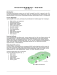
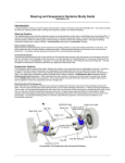


![Overview cPR67 and cPR84 [v00]](http://vs1.manualzilla.com/store/data/005648847_1-d158a5d3d4b92d14c7a3179652b88ffd-150x150.png)