1
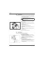
CLIPLINE
UM EN CF 3000-2,5 (2888149)
EN
User Manual
CF 3000-2,5
CF 3000-2,5 120 V
English
CLIPLINE
User Manual
Stripping and crimping automat for insulated ferrules in reel packaging
CF 3000
2010-08-16
Designation:
UM EN CF 3000-2,5
Revision:
01
Order No.:
2888149
This user manual is valid for:
Designation
Order No.
CF 3000-2,5
1205477
CF 3000-2,5 120 V
1205516
102649_en_01
PHOENIX CONTACT
CF 3000
Please observe the following notes
In order to ensure the safe use of the product described, you have to read and understand
this manual. The following notes provide information on how to use this manual.
User group of this manual
The use of products described in this manual is oriented exclusively to qualified electricians
or persons instructed by them, who are familiar with applicable standards and other
regulations regarding electrical engineering and, in particular, the relevant safety concepts.
Phoenix Contact accepts no liability for erroneous handling or damage to products from
Phoenix Contact or third-party products resulting from disregard of information contained in
this manual.
Explanation of symbols used and signal words
This is the safety alert symbol. It is used to alert you to potential personal injury
hazards. Obey all safety messages that follow this symbol to avoid possible
injury or death.
DANGER
This indicates a hazardous situation which, if not avoided, will result in death or serious
injury.
WARNING
This indicates a hazardous situation which, if not avoided, could result in death or serious
injury.
CAUTION
This indicates a hazardous situation which, if not avoided, could result in minor or
moderate injury.
The following types of messages provide information about possible property damage
and general information concerning proper operation and ease-of-use.
NOTE
This symbol and the accompanying text alerts the reader to a situation which may cause
damage or malfunction to the device, either hardware or software, or surrounding
property.
This symbol and the accompanying text provides additional information to the reader.
It is also used as a reference to other sources of information (manuals, data sheets,
literature) on the subject matter, product, etc.
PHOENIX CONTACT
102649_en_01
General terms and conditions of use for technical documentation
Phoenix Contact reserves the right to alter, correct, and/or improve the technical documentation and the products described in the technical documentation at its own discretion and without giving prior notice, insofar as this is reasonable for the user. The same applies to any technical changes that serve the purpose of technical progress.
The receipt of technical documentation (in particular data sheets, installation instructions, manuals, etc.) does not constitute any further duty on the part of Phoenix Contact to furnish information on alterations to products and/or technical
documentation. Any other agreement shall only apply if expressly confirmed in writing by Phoenix Contact. Please
note that the supplied documentation is product-specific documentation only and that you are responsible for checking the suitability and intended use of the products in your specific application, in particular with regard to observing
the applicable standards and regulations.
Although Phoenix Contact makes every effort to ensure that the information content is accurate, up-to-date, and stateof-the-art, technical inaccuracies and/or printing errors in the information cannot be ruled out. Phoenix Contact does
not offer any guarantees as to the reliability, accuracy or completeness of the information. All information made available in the technical data is supplied without any accompanying guarantee, whether expressly mentioned, implied or
tacitly assumed. This information does not include any guarantees regarding quality, does not describe any fair marketable quality, and does not make any claims as to quality guarantees or guarantees regarding the suitability for a
special purpose.
Phoenix Contact accepts no liability or responsibility for errors or omissions in the content of the technical documentation (in particular data sheets, installation instructions, manuals, etc.).
The aforementioned limitations of liability and exemptions from liability do not apply, in so far as liability must be assumed, e.g., according to product liability law, in cases of premeditation, gross negligence, on account of loss of life,
physical injury or damage to health or on account of the violation of important contractual obligations. Claims for damages for the violation of important contractual obligations are, however, limited to contract-typical, predictable damages, provided there is no premeditation or gross negligence, or that liability is assumed on account of loss of life,
physical injury or damage to health. This ruling does not imply a change in the burden of proof to the detriment of the
user.
Statement of legal authority
This manual, including all illustrations contained herein, is copyright protected. Use of this manual by any third party
is forbidden. Reproduction, translation, and public disclosure, as well as electronic and photographic archiving or alteration requires the express written consent of Phoenix Contact. Violators are liable for damages.
Phoenix Contact reserves all rights in the case of patent award or listing of a registered design. Third-party products
are always named without reference to patent rights. The existence of such rights shall not be excluded.
How to contact us
Internet
Up-to-date information on Phoenix Contact products and our Terms and Conditions can be
found on the Internet at:
www.phoenixcontact.com.
Make sure you always use the latest documentation.
It can be downloaded at:
www.phoenixcontact.net/catalog.
Subsidiaries
Published by
If there are any problems that cannot be solved using the documentation, please contact
your Phoenix Contact subsidiary.
Subsidiary contact information is available at www.phoenixcontact.com.
.
PHOENIX CONTACT GmbH & Co. KG
Flachsmarktstraße 8
32825 Blomberg
Germany
Phone +49 (0) 52 35 – 3-00
Fax
+49 (0) 52 35 – 3-4 12 00
PHOENIX CONTACT
P.O. Box 4100
Harrisburg, PA 17111-0100
USA
Phone +1-717-944-1300
Should you have any suggestions or recommendations for improvement of the contents and
layout of our manuals, please send your comments to
[email protected].
102649_en_01
PHOENIX CONTACT
English
CF 3000
CF 3000
Table of contents
1
2
3
4
5
i
Basic instructions ....................................................................................................................1-1
1.1
Intended purpose .............................................................................................. 1-1
1.2
Work sites........................................................................................................... 1-2
1.3
For your safety.................................................................................................... 1-2
Description of the CF 3000 .....................................................................................................2-1
2.1
Scope of delivery ................................................................................................ 2-1
2.2
Overview of the operating components .............................................................. 2-2
Putting into operation ..............................................................................................................3-1
3.1
Selecting the installation site .............................................................................. 3-1
3.2
Preparing the dispenser ..................................................................................... 3-1
Operation ................................................................................................................................4-1
4.1
Stripping and crimping........................................................................................ 4-1
4.2
Converting to other cross-sections ..................................................................... 4-2
4.3
Service ............................................................................................................... 4-4
Rectifying malfunctions ...........................................................................................................5-1
PHOENIX CONTACT
5.1
Maintenance position ......................................................................................... 5-1
5.2
Fault cases ......................................................................................................... 5-1
5.3
Fault case 1 ........................................................................................................ 5-1
5.4
Fault case 2 ........................................................................................................ 5-2
5.5
Fault case 3 ........................................................................................................ 5-2
5.6
Fault case 4 ........................................................................................................ 5-3
5.7
Fault case 5 ........................................................................................................ 5-3
5.8
Fault case 6 ........................................................................................................ 5-4
5.9
Fault case 7 ........................................................................................................ 5-4
102649_en_01
1
Basic instructions
For simplification, only the item name CF 3000 is used in the following.
Basic condition for the proper safe handling and fault-free operation of the CF 3000 is the
knowledge and observation of the safety instructions.
1.1
Intended purpose
WARNING: The CF 3000 is intended solely for stripping and crimping.
Only the PVC-insulated conductors may be inserted into the insertion funnel on the
CF 3000 for processing; under no circumstance massive metal parts or like objects.
Arbitrary conversions that go beyond the retrofitting and modifications on the CF 3000
are prohibited for safety reasons.
ATTENTION: Observing all information and the adhering to the prescribed operational
conditions belong to the intended purpose.
WARNING: The CF 3000 may only be used
– for the intended purpose and
– when in safe and fault-free condition.
WARNING: All persons that are involved with the startup, operation, and maintenance
of the CF 3000 have to
– be appropriately qualified and
– adhere strictly to this user manual.
The CF 3000 serves to fully automatically strip flexible conductors of the classes 2, 5, and
6 according to DIN VDE 0295 and subsequent pressing insulated ferrules from reel packaging.
Ferrules are processed according to DIN 46228-4 in the cross-section range
0.5 mm² … 2.5 mm² with 8 mm stripping length (order data, see page B-1).
Furthermore, an additional fit can be used to process ferrules in the cross-section range
0.25 mm² … 0.34 mm² with 8 mm stripping length (order data, see page B-1).
ATTENTION: Use only ferrules and spare parts from Phoenix Contact
(order data, see page B-1).
Permitted operators
Only authorized and instructed operators may work with the CF 3000.
The owner must
– make the user manual available to the operator and
– ensure that the operator has read and understood it.
102649_en_01
PHOENIX CONTACT
1-1
English
Basic instructions
CF 3000
1.2
Work sites
ATTENTION: For operation and storage, avoid the following:
– Humid or dusty places and
– Places that are subject to high warmth, direct sunlight, or low temperatures
(operating range: 15 °C to 35 °C).
ATTENTION:
If there is a move from a cold room to a warm room, condensation can form.
•
Before using the CF 3000, open the front door and allow condensation to evaporate.
ATTENTION:
•
Do not spill liquids on the CF 3000.
•
Do not let the CF 3000 be shaken or jolted heavily.
ATTENTION:
The CF 3000 may be used only when the hood is closed.
•
Pull the mains plug before any work on the CF 3000, such as cross-section exchange
or maintenance work.
1.3
For your safety
WARNING: The hood is installed for your safety. You should not modify the hood under
any circumstances, remove it or bridge it by conversions.
WARNING:
The CF 3000 may be used only when the hood is closed.
•
Pull the mains plug before any work on the CF 3000, such as cross-section exchange
or maintenance work.
•
Make sure that there are no foreign objects inside the housing.
1-2
PHOENIX CONTACT
102649_en_01
2
Description of the CF 3000
2.1
Scope of delivery
2
1
3
4
5
7
6
102649a001
Illustration 2-1 Scope of delivery
1
2
3
4
5
6
7
Basic device CF 3000
Power cable (different types for CF 3000-2,5 and CF 3000-2,5 120 V)
Container for insulation residues
Ferrule guide for ferrules 0.5 mm² … 2.5 mm² (5 pieces)
and per cross-section, one spare ferrule guide and a cable guide (not shown)
Operational inserts for 0.5 mm² … 2.5 mm² (5 pieces)
Replacement locator for each operational insert (5 pieces)
Securing bolt ø 6 mm
The ferrule guide and the operational inserts have the same color codes as the ferrule
(according to DIN color code). They are supplied in a case. The case also includes a small
brush (see page 4-4).
You can order a kit for 0.25 mm² and 0.34 mm² (order data, see page B-1).
102649_en_01
PHOENIX CONTACT
2-1
English
Description of the CF 3000
CF 3000
2.2
Overview of the operating components
1
2
3
4
5
16
9 8
15
10
14
13
12
7
6
11
102649a002
Illustration 2-2 Operating components
1
Handle
2
Counter
The counter indicates the number of
processing procedures.
10 Mains fuses
Microfuses integrated in the mains connection.
3
Reset button
The counter can be reset to 0 with
this button.
11 Mains switch
Switches the power supply of the CF 3000
on or off.
4
Power-on
indicator
Lights up when the power supply
is switched on.
12 Transformer
fuse
Secondary devise fuse with
microfuse 4.0 A/T/250 V.
5
Insertion
funnel
To feed the conductor into the
CF 3000.
13 Reverse
button
Device moves into maintenance position
(see page 5-1)
6
Operational
insert
Positions the ferrule and strips
the cable.
14 Ferrule dispenser holder
Holder for the ferrule dispenser.
7
Securing
bolt
Locks the operational insert.
15 Container
The container collects the insulation residues. Empty the container regularly.
8
Hood
The hood is there for your safety.
The CF 3000 functions only when
the hood is closed completely.
16 Ferrule guide
The ferrule guide positions the ferrules.
The corresponding guide needs to be
installed for every cross-section.
2-2
9
PHOENIX CONTACT
Mains
connection
Device connection for the power cable
102649_en_01
3
Putting into operation
3.1
Selecting the installation site
ATTENTION: The installation site needs to be level and horizontal.
ATTENTION: During operation and storage, avoid the following:
– Humid or dusty places
– Places that are subject to high warmth, direct sunlight, or low temperatures
(operating range: 15 °C … 35 °C).
ATTENTION: If there is a move from a cold room to a warm room, condensation can form.
•
Before using the CF 1000, open the hood and allow condensation to evaporate.
ATTENTION:
•
Do not spill liquids on the CF 3000.
•
Do not let the CF 3000 be shaken or jolted heavily.
3.2
Preparing the dispenser
•
Open the package of the corresponding reel ferrules, tear off
the strap at the edge (1) and pull out the reel about 20 cm (2).
Preparing the ferrule guide
ATTENTION: Insert the ferrules precisely as directed,
otherwise there may be faulty crimpings. Observe the
color code of the ferrule guide.
•
•
•
Select a ferrule guide with the corresponding cross-section.
Insert the ferrules in the corresponding guide all the way
sidewise (1).
Then pull the pin upwards (2) and push the ferrules further to
the marking (3).
ATTENTION: Make sure that the pin has latched in
securely.
102649_en_01
PHOENIX CONTACT
3-1
English
Putting into operation
CF 3000
Mounting the ferrule guide
ATTENTION: The operational insert should not be
mounted yet.
•
•
Push back the hood.
Insert the ferrule guide sidewise into the CF 3000 and plug onto
the locating bolts in the front plate.
The ferrule guide has to be seated directly at the housing panel.
ATTENTION: Make sure that the pin has latched in
securely.
•
Place the dispenser of the ferrules into the holder.
Mounting the operational insert
•
Select an operational insert with the corresponding cross-section.
ATTENTION: Note the color code of the operational
insert.
•
•
1
2
•
Push the operational insert sidewise into the intended
guide (1).
Insert the securing bolt all the way into the borehole of the
operational insert (2).
Tip over the holder of the dispenser so that it stands at a right
angle to the CF 3000.
ATTENTION: Make sure that the ferrule reel can run
unhindered.
•
Close the hood.
Connecting the power supply
ATTENTION: The CF 3000 is available in two variants
for 230 V and 120 V. Make sure the mains connection is
correct (see type plate).
•
Connect the power cable and switch on the CF 3000.
The CF 3000 is now ready for operation.
3-2
PHOENIX CONTACT
102649_en_01
4
Operation
4.1
Stripping and crimping
Align the conductor
b
a
•
The conductor has to be aligned as straight as possible before
the processing.
a) Bend is OK, maximum 2–3 mm at 6 mm length
b) Bend too great
Cutting the conductor
c
a
b
•
Cut off the conductor clean and straight, for example with
the cable cutter CUTFOX 35 (item no. 1206638) from
Phoenix Contact.
a)
b)
c)
d)
d
Proper cut
Cut surface angled
Cut surface squeezed, single wires pulled out
Cut surface squeezed
Stripping and crimping
2
1
•
Close the hood (1).
•
If necessary, read the counter (2) and reset to 0.
•
Switch on the CF 3000 with the mains switch.
•
Push the conductor (4) straight all the way into the insertion
funnel.
The stripping and crimping process starts automatically.
•
After the standstill of the CF 3000, pull the conductor straight
out.
In case of a malfunction or otherwise improper
stripping, see page 5-1.
4
Putting out of operation
102649_en_01
•
If necessary, read the counter and reset to 0.
•
Switch off the CF 3000 with the mains switch.
PHOENIX CONTACT
4-1
English
Operation
CF 3000
4.2
Converting to other cross-sections
The CF 3000 can be converted to the cross-sections 0.5 mm², 0.75 mm², 1.0 mm², 1.5 mm²
and 2.5 mm².
Operational set, ferrule guide, and reel ferrules of a cross-section are marked by colors
(color code according to DIN 46288-4).
Preparing the conversion
WARNING: Risk of injury!
The hood needs to be opened. Pull the mains plug
before opening the hood!
1
•
If necessary, read the counter and reset to 0.
•
Switch off the CF 3000 with the mains switch.
•
Pull the mains plug.
•
Push back the hood.
•
Pull the securing bolt for the operational insert (1).
•
Remove the operational insert (2).
2
Replacing the ferrule guide
1
•
Pull the pin upwards and pull out the ferrules.
•
Remove the dispenser and roll up the remaining ferrules.
Fold in the holder.
•
Pull the ferrule guide backwards (towards the handle) (1) and
remove sidewise from the CF 3000 (2).
Preparing the ferrule guide
2
ATTENTION: Insert the ferrules precisely as directed,
otherwise there may be faulty crimpings. Observe the
color code of the ferrule guide.
•
Select a ferrule guide with the corresponding cross-section.
•
Insert the ferrules in the corresponding guide all the way
sidewise (1).
•
Then pull the pin upwards (2) and push the ferrules further to
the marking (3).
ATTENTION: Make sure that the pin has latched in
securely.
4-2
PHOENIX CONTACT
102649_en_01
Mounting the ferrule guide
ATTENTION: The operational insert should not be
mounted yet.
•
Push back the hood.
•
Insert the ferrule guide sidewise into the CF 3000 and plug onto
the locating bolts in the front plate.
The ferrule guide has to be seated directly at the housing panel.
ATTENTION: Make sure that the pin has latched
in securely.
•
Place the dispenser of the ferrules on the holder so that the ferrules reel is fed from bottom to top in the ferrule guide.
Mounting the operational insert
Select an operational insert with the corresponding cross-section.
ATTENTION: Note the color code of the operational
insert.
1
•
Push the operational insert sidewise into the intended
guide (1).
•
Insert the securing bolt all the way into the borehole of the
operational insert (2).
•
Tip over the holder of the dispenser so that it stands at a right
angle to the CF 3000.
2
ATTENTION: Make sure that the ferrule reel can run
unhindered.
•
Close the hood.
Connecting the power supply
ATTENTION: The CF 3000 is available in two variants
for 230 V and 120 V. Make sure the mains connection is
correct (see type plate).
•
Connect the power cable and switch on the CF 3000.
The CF 3000 is now ready for operation.
102649_en_01
PHOENIX CONTACT
4-3
English
Operation
CF 3000
4.3
Service
Clean the CF 3000 daily
•
If necessary, read the counter and reset to 0.
WARNING: Risk of injury!
Pull the mains plug and disconnect the compressed air
before you open the front door.
•
Switch off the CF 3000 with the mains switch.
•
Pull the mains plug.
•
Open the hood.
•
Empty the container for insulation residues daily.
•
Check if there are any insulation residue inside of the CF 3000
and remove them.
•
Insert the container.
•
Close the hood.
Cleaning the insertion funnel
•
4-4
PHOENIX CONTACT
If the insertion funnel is soiled, it can be cleaned by a brush
(included in the scope of delivery).
102649_en_01
5
Rectifying malfunctions
5.1
Maintenance position
The maintenance position is used for removing replaceable parts in case of faulty crimping
or jammed-in conductors.
The control drives automatically into maintenance position in case the crimping was not
completed. It may happen that the CF 3000 carries out the crimping cycle through to the end
position despite a faulty crimping. In this case, press the Reverse button to drive the
CF 3000 into maintenance position.
5.2
Table 5-1
Fault cases
Fault cases
Fault/malfunction
Rectification
Fault case
number
See
Conductor cannot be inserted
Press the Reverse button
Fault case 1
Page 5-1
Crimping process not ended
Remove conductor
Fault case 2
Page 5-2
Conductor jams in the CF 3000
Remove conductor
Fault case 2
Page 5-2
Conductor insulation is removed incompletely
–
Fault case 3
Page 5-2
–
Check cross-section
specifications
Check stripping knife
Ferrule is not separated from the reel
Check the separating knife of the
locator
Fault case 4
Page 5-3
CF 3000 does not function when the main switch
is turned on
Check mains connection/fuses
Fault case 5
Page 5-3
CF 3000 works too slow
Check transformer fuse
Fault case 6
Page 5-4
Centering fork defective
Exchange centering forks
Fault case 7
Page 5-4
5.3
Fault case 1
The conductor cannot be inserted
The conductor can only be inserted in the start position (front) and
not in the maintenance position (back).
• Press the Reverse button to get into the start position.
102649_en_01
PHOENIX CONTACT
5-1
English
Rectifying malfunctions
CF 3000
5.4
Fault case 2
The crimping process was not ended or the conductor is jammed in the CF 3000
•
•
If the conductor jams in the CF 3000, press the Reverse button
to get into maintenance position.
If necessary, read the counter and reset to 0.
WARNING: Risk of injury!
The hood needs to be opened. Pull the mains plug
before opening the hood!
•
•
Switch off the CF 3000 with the mains switch.
Pull the mains plug.
Remove the operational insert and take out the conductor
•
•
•
•
•
•
•
5
1
4
3
•
2
•
Push back the hood.
Remove the securing bolt and pull the operational insert out to
the side (3).
Remove the ferrules (4).
Bend the conductor to the side (5).
Pull the pin upwards and pull out the ferrules.
Close the hood.
Plug in the mains plug. Switch on the CF 3000 with the mains
switch.
Press the Reverse button again. The CF 3000 move into the
start position.
Pull out the conductor.
Set up the CF 3000 after that (see page 3-1).
5.5
Fault case 3
The conductor insulation is removed incompletely
Check cross-section specifications
•
•
If the stripping of the conductor is not removed completely,
check the cross-section specifications.
The conductor cross-section needs to match the cross-section
specifications of operational insert and ferrule guide.
Match the inserts to the selected conductor cross-section
(see page 4-2).
Replacing the stripping knife
•
•
•
5-2
PHOENIX CONTACT
Check if the stripping knives (1) are damaged.
If the stripping knives of the operational insert are worn or damaged, they need to be replaced (item no., see page B-1).
Loosen the Allen head screw (2), replace the stripping knives
and retighten the screw.
102649_en_01
5.6
Fault case 4
The ferrule is not separated from the reel
Replacing the locator
If the separating knife (1) is damaged or broken off, the ferrule that
is crimped to the conductor will not be separated from the reel.
• Remove the operational insert (see page 4-2).
• Check the separating knife (1). If the separating knife (1)
is defective, remove the locator (3).
• Loosen the Phillips screw (2).
• Remove the locator.
• Install a new locator for the corresponding cross-section
(item number, see page B-1).
• Tighten the Phillips screw (2).
5.7
Fault case 5
The CF 3000 does not function when the main switch is turned on
•
Make sure that the connections between the CF 3000 and the socket has been established without fault.
Checking the mains fuses
WARNING: Risk of injury!
The hood needs to be opened. Pull the mains plug
before opening the hood!
•
•
•
•
•
Switch off the CF 3000 with the mains switch.
Pull the mains plug (1).
Pull out the fuse holder (2).
Replace the defective mains fuses (3) with microfuses:
2 x 0.63 A/T/250 V (CF 3000-2,5) or otherwise
2 x 1.25 A/T/120 V (CF 3000-2,5 120 V),
(item no., see page B-1).
Insert the fuse holder.
ATTENTION: The fuse holder has to snap in.
102649_en_01
PHOENIX CONTACT
5-3
English
Rectifying malfunctions
CF 3000
5.8
Fault case 6
The CF 3000 works too slow
Checking the transformer fuse
WARNING: Risk of injury!
The hood needs to be opened. Pull the mains plug
before opening the hood!
•
•
•
•
•
5.9
Switch off the CF 3000 with the mains switch.
Pull the mains plug (1).
Turn out the fuse holder (2) with a suitable screwdriver.
Replace the defective fuses (3) with microfuses
(4.0 A/T/250 V, item no., see page B-1).
Turn the fuse holders back in.
Fault case 7
Top centering fork (crimp die) or bottom centering fork (crimp casting) are
defective
Exchanging the centering forks
WARNING: Risk of injury!
The hood needs to be opened. Pull the mains plug
before opening the hood!
•
•
•
•
•
•
•
Switch off the CF 3000 with the mains switch.
Pull the mains plug.
Remove the operational insert and the ferrule guide
(see page 4-2).
To remove the bottom centering fork (1) and the top centering
fork (2), loosen the respective Allen head screws (3).
Take out the bottom centering fork. Press the top crimp casting
a few millimeters down for that.
Press down the hose clamp (4), pull out the hose (5) and remove the top centering fork.
Replacing defective centering forks with new ones
(item no., see page B-1).
ATTENTION: The plastic parts have to be clean and
free of grease.
5-4
PHOENIX CONTACT
102649_en_01
English
A Technical Annex
A1
Technical data
Technical data
Mains connection
CF 300-2,5
CF 3000-2,5 120 V
230 V/50 Hz
120 V/60 Hz
Power consumption
80 VA
Cycle time
1.2 s
Work range
0.5 mm² … 2.5 mm²
Ferrules
Reel packaging version acc. to DIN 46228-4
Conductor length minimum
49 mm
Stripping length
8 mm
with conversion kit (CF 3000-TOOLKIT 0,25) 0.25 mm² and 0.34 mm²
Press form
Trapeze-shaped according to DIN VDE 0660-100
Dimension (W x H x D)
320 mm x 300 mm x 165 mm
Weight
12 kg
Operational temperature
15 °C … 35 °C
Noise levels
70 dB (A)
102649_en_01
PHOENIX CONTACT
A-1
CF 3000
A2
Declaration of Conformity
PHOENIX CONTACT GmbH & Co.KG, Flachsmarktstraße 8, D-32825 Blomberg, Germany
CF 3000-2,5
CF 3000-2,5 120 V
The products are in conformity with significant standards of the following regulations and
their change regulations.
2004/108/EC
EMC guideline (Electromagnetic Compatibility)
2006/42/EC
Machinery Directive
2006/95/EC
Low voltage directive
The following pertinent standards were consulted for evaluating the conformity:
EN ISO 12100-1:2003
EN ISO 12100-2_2003
EN ISO 13857:2008
EN 349:1993 + A1
EN 60204-1:2006
EN 61000-6-3:2007
EN 61000-6-2:2005
A-2
PHOENIX CONTACT
102649_en_01
English
B Order data
B1
Stripping and crimping automat
Description
Designation
Item no.
VPE
Stripping and crimping automat, 230 V version
for insulated ferrules in reel packaging according to DIN 46228-4,
for cross-section range 0.5 mm2 … 2.5 mm2
CF 3000
1205477
1
Stripping and crimping automat, 120 V version
for insulated ferrules in reel packaging according to DIN 46228-4,
for cross-section range 0.5 mm2 … 2.5 mm2
CF 3000-2,5 120 V
1205516
1
Kit for CF 3000, 0.25 mm² and 0.34 mm², complete
CF 3000-TOOLKIT 0,25
1212376
1
B2
Reel ferrules
Description
Designation
Item no.
Pcs./
reel
Reel ferrules with plastic ferrule, 0.25 mm², blue
AI 0,25-8 BU-B
3240250
1000
Reel ferrules with plastic ferrule, 0.25 mm², yellow
AI 0,25-8 YE-B
3240251
1000
Reel ferrules with plastic ferrule, 0.34 mm², turquoise
AI 0,34-8 TQ-B
3240249
1000
Reel ferrules with plastic ferrule, 0.5 mm², white
AI 0,5-8 WH-B1
3201369
1000
Reel ferrules with plastic ferrule, 0.5 mm², orange
AI 0,5-8 OG-B
3201563
1000
3201372
1000
1
Reel ferrules with plastic ferrule, 0.75 mm², gray
AI 0,75-8 GY-B
Reel ferrules with plastic ferrule, 0.75 mm², blue
AI 0,75-8 BU-B
3201547
1000
Reel ferrules with plastic ferrule, 0.75 mm², white
AI 0,75-8 WH-B
3201576
1000
Reel ferrules with plastic ferrule, 1 mm², red
AI 1-8 RD-B1
3201385
1000
Reel ferrules with plastic ferrule, 1 mm², yellow
AI 1-8 YE-B
3201589
1000
Reel ferrules with plastic ferrule, 1.5 mm², black
AI 1,5-8 BK-B1
3201398
1000
Reel ferrules with plastic ferrule, 1.5 mm², red
AI 1,5-8 RD-B
3201592
1000
Reel ferrules with plastic ferrule, 2.5 mm², blue
AI 2,5-8 BU-B1
3201408
500
Reel ferrules with plastic ferrule, 2.5 mm², gray
AI 2,5-8 GY-B
3201550
500
1
Color code according to DIN 46228-4
B3
Part
Operational insert
102649_en_01
Spare parts
Cross-section
Designation
Item no.
VPE
0.25 mm²
CF 3000 BBE-AME 0,25
1207514
1
0.5 mm²
CF 3000 BBE 0,5
1205752
1
0.75 mm²
CF 3000 BBE 0,75
1205765
1
1.0 mm²
CF 3000 BBE 1,0
1205778
1
1.5 mm²
CF 3000 BBE 1,5
1205781
1
2.5 mm²
CF 3000 BBE 2,5
1205794
1
PHOENIX CONTACT
B-1
CF 3000
Part
Cross-section
Designation
Item no.
VPE
Locator
0.25 mm²
CF 3000 LOC 0,25
1212377
1
The locator is a component
of the operational insert
CF 3000 BBE…
0.5 mm²
CF 3000 LOC 0,5
1205639
1
2.5 mm²
CF 3000 LOC 0,75
1205642
1
1.0 mm²
CF 3000 LOC 1,0
1205655
1
1.5 mm²
CF 3000 LOC 1,5
1205668
1
2.5 mm²
CF 3000 LOC 2,5
1205671
1
Stripping knife
0.25 mm²
CF 3000 AB 0,25
1212380
1
The stripping knife is a
component of the operational insert CF 3000
BBE…
0.5 mm²
CF 3000 AM 0,5
1205587
1
2.5 mm²
CF 3000 AM 0,75
120559 0
1
1.0 mm²
CF 3000 AM 1,0
1205600
1
1.5 mm²
CF 3000 AM 1,5
1205613
1
2.5 mm²
CF 3000 AM 2,5
1205626
1
0.25 mm²
CF 3000 HZG 0,25
1212378
1
0.5 mm²
CF 3000 HZG 0,5
1205684
1
2.5 mm²
CF 3000 HZG 0,75
1205697
1
1.0 mm²
CF 3000 HZG 1,0
1205707
1
1.5 mm²
CF 3000 HZG 1,5
1205710
1
2.5 mm²
CF 3000 HZG 2,5
1205723
1
Cable guide
0.25 mm²
CF 3000 CG 0,25
1212379
1
The cable guide is a component
of the ferrule guide
CF 3000 HZG…
0.5 mm²
CF 3000 CG 0,5
1207721
1
2.5 mm²
CF 3000 CG 0,75
1207734
1
1.0 mm²
CF 3000 CG 1,0
1207747
1
1.5 mm²
CF 3000 CG 1,5
1207750
1
2.5 mm²
CF 3000 CG 2,5
1207763
1
Securing bolt
–
CF 3000 SBO
1205804
1
Centering fork up
0.5 mm2 … 2.5 mm2
CF 3000 CENTERING FORK UP
3202740
1
0.25 mm² … 0.75 mm²
CF 3000 CFT 0,25
1212391
1
0.5 mm2 … 2.5 mm2
CF 3000 CENTERING FORK DOWN
3202753
1
0.25 mm² … 0.75 mm²
CF 3000 CFB 0,25
1212392
1
0.5 mm2 … 2.5 mm2
CF 3000 CRIMP DIE
3202782
1
0.25 mm² … 0.75 mm²
CF 3000 CDM 0,25
1212390
1
0.5 mm2 … 2.5 mm2
CF 3000 CRIMP CASTING
3202779
1
0.25 mm² … 0.75 mm²
CF 3000 CDF 0,25
1212389
1
Mains fuse
Microfuses integrated in
the mains connection
0.63 A/T/250 V, for the
CF 3000-2,5
CF 3000 SI 0,63 A/T/250 V
1205736
2
Mains fuse
Microfuses integrated in the
mains connection
1.25 A/T/120 V, for the
CF 3000-2,5 120 V
CF 3000 SI 1,25 A/T/120 V
1208940
2
Transformer fuse
Transformer fuse, secondary
with microfuse 4.0 A/T/250 V
CF 3000 SI 4,0 A/T/250 V
1205749
2
Ferrule guide
Centering fork down
Crimp die
Crimp casting
B-2
PHOENIX CONTACT
102649_en_01