Transcript
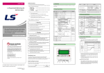
DATA SHEET LS Programmable Logic Controller Analog Output Module XGB Safety Precautions ► Safety Precautions is for using the product safely and correctly in order to prevent the accidents and danger, so please go by them. ► The precautions explained here only apply to this module. For safety precautions on the PLC system, refer to User’s manual. ► The precautions are divided into 2 sections, ‘Warning’ and ‘Caution’. Each of the meanings is represented as follows. If you violate instructions, it can cause death, fatal injury or a Warning considerable loss of property XBF-DV04A XBF-DC04A XBF-DC04B Caution If you violate instructions, it can cause a slight injury or a slight loss of products ► The symbols which are indicated in the PLC and User’s Manual mean as follows. This symbol means paying attention because of danger of injury, fire, or malfunction ► This symbol means paying attention because of danger of electric shock. Store this datasheet in a safe place so that you can take it out and read it whenever necessary. Always forward it to the end user Related Manual Read this data sheet carefully prior to any operation, mounting, installation or start-up of the product. Name Code XGB analog 10310000862 XGK XGB Instruction & Programming 10310000509 XGI XGR XEC Instruction & Programming 10310000739 XGB Hardware 10310000893 XGB Hardware (IEC) 10310000981 XG5000 10310000511 Revision History Date 2006. 11 2009.05 2011. 05 Version V1.0 V2.0 Updated Information First Edition Error in performance specifications is fixed KOREAN/ENGLISH data sheet integrated CI Changed V3.0 Applicable version For system configuration, the following version is necessary. Item Applicable Version XG5000 V3.6 or above Handling Precautions ► Don’t drop or make impact. ► Don’t detach PCB from case. It may cause problem. ► When wiring, let no foreign material go into the module. If it goes into the module, remove it. ► Don’t detach the module from slot while power is on 1. General Specifications No 1 2 - When using LSIS equipment, thoroughly read this datasheet and associated manuals introduced in this datasheet. Also pay careful attention to safety and handle the module properly. - Store this datasheet in a safe place so that you can take it out and read it whenever necessary. Warning 3 4 ► Do not contact the terminals while the power is applied. Risk of electric shock and malfunction. ► Protect the product from being gone into by foreign metallic matter. Risk of fire, electric shock and malfunction. ► Risk of fire, electric shock and malfunction. Risk of injury and fire by explosion and ignition. 5 6 HEAD OFFICE LS Tower, 127, LS-ro, Dongan-gu, Anyang-si,Gyeonggi-do, 431-848, Korea Tel: 82-2-2034-4870 Fax: (82-2)2034-4648 e-mail: [email protected] Caution ► Be sure to check the rated voltage and terminal arrangement for the module before wiring work. Risk of electric shock, fire and malfunction. LSIS(ME) FZE _ Dubai, U.A.E. Tel: 971-4-886-5360 Fax: 971-4-886-5361 e-mail: [email protected] ► Tighten the screw of terminal block with the specified torque range. If the terminal screw is loose, it can cause fire and electric shock. LSIS Tokyo Office _ Tokyo, Japan Tel: 81-3-3582-9128 Fax: 81-3-3582-2667 . e-mail: [email protected] ► Use the PLC in an environment that meets the general specifications contained in this datasheet. Risk of electrical shock, fire, erroneous operation and deterioration of the PLC. LSIS Shanghai Office _ Shanghai, China Tel: 86-21-5237-9977(609) Fax: 89-21-5237-7189 e-mail: [email protected] LSIS Beijing Office _ Beijing, China Tel: 86-10-5825-6027(666) Fax: 86-10-5825-6028 ► Be sure that external load does not exceed the rating of output module. Risk of fire and erroneous operation. e-mail: [email protected] ► Do not use the PLC in the environment of direct vibration Risk of electrical shock, fire and erroneous operation. LSIS Guangzhou Office _ Guangzhou, China Tel: 86-20-8328-6754 Fax: 86-20-8326-6287 e-mail: [email protected] LSIS Chengdu Office _ Chengdu, China Tel: 86-20-8328-6754 Fax: 86-20-8326-6287 e-mail: [email protected] 7 Specification Standard 0 ~ 55℃ - -25 ~ 70℃ Operating humidity Storage humidity - 5 ~ 95%RH, non-condensing - 5 ~ 95%RH, non-condensing - For discontinuous vibration Acceleration Amplitude Frequency times 10≤f∠57 Hz 0.075 mm 10 times in Vibration 57 ≤f≤150 Hz 9.8㎨ (1G) each resistance For continuous vibration direction Acceleration Amplitude Frequency for 10≤f∠57 Hz 0.035 mm X, Y, Z 57≤f≤150 Hz 4.9㎨(0.5G) Max. impact acceleration : 147 ㎨ (15G) Shocks Authorized time : 11㎳ resistance Pulse wave : Sign half-wave pulse (Each 3 times in X,Y,Z directions) Square wave AC: ±1,500V impulse noise DC: ±900V Electrostatic Voltage: 4kV (Contact discharge) discharge Noise resistance Radiated electromagnetic field noise Fast transient /burst noise 8 9 10 11 ► Do not disassemble, repair or modify the PLC. Risk of electrical shock, fire and erroneous operation Item Operating temperature Storage temperature Ambient conditions Operating height Pollution degree Cooling type Power supply module Voltage 2 kV Item Type Analog output Range Specifications XBF-DC04A XBF-DC04B Current DC 4 ~ 20㎃ DC 0 ~ 10V DC 0 ~ 1.2㎃ DC 0 ~ 20㎃ (Load (Load (Load resistance: resistance: resistance: 2kΩ or more) 510Ω or less) 510Ω or less) Signed 12 bit binary data XBF-DV04A Voltage Type Unsigned 0 ~ 4000 0 ~ 4000 0 ~ 4000 value Singed Digital -2000 ~ 2000 -2000 ~ 2000 -2000 ~ 2000 Value input Range Precise 400 ~ 2000 0 ~ 1000 0 ~ 1200 Value 0 ~ 2000 Percentile 0 ~ 1000 0 ~ 1000 0 ~ 1000 Value Max. resolution 2.5㎷(1/4000) 5㎂(1/4000) 0.3㎂(1/4000) Accuracy ±0.5% or less Max. conversion speed 1㎳/Channel Absolute max. output DC ±15V DC +25㎃ Output channel 4 Channel Photo-coupler insulation between output Insulation method terminal and PLC power (no insulation between channels) Terminal connected 11 Point terminal I/O occupied points Fixed point assignment: 64 Point Internal(DC 5V) 110㎃ 110㎃ Consumed External current 70㎃ 120㎃ (DC 21.6~26.4V) Weight 64g 70g 3. Parts Names and Descriptions - IEC61131-2 IEC61131-2 LSIS standard IEC61131-2 IEC61000-4-2 IEC61131-2 IEC61000-4-3 80 ~ 1,000 MHz, 10 V/m Segment 2. Performance Specifications Digital/analog input/output communication interface 1 kV IEC61131-2 IEC61000-4-4 No corrosive gas or dust No. - 2000m or less - 2 or less - Natural air cooling - ① ② ③ Part Name Description Displays the operation status On: Operation normal Blink: Error occurs Off: DC 5V disconnected, Module error Analog output Analog output(voltage, current) terminal, terminal whose respective channels can be connected (voltage, current) with external devices External power input External power input terminal supplied DC terminal 24V for analog output(voltage, current) RUN LED ► When disposing of PLC and battery, treat it as industrial waste. Risk of poisonous pollution or explosion. LSIS Qingdao Office _ Qingdao, China Tel: 86-532-8501-6068 Fax: 86-532-8501-6057 e-mail: [email protected] LSIS Europe B.V., Netherlands Tel: +31 (0)20 654 1420 Fax: +31(0)20 654 1429 e-mail: [email protected] Precautions for use ► Do not Install other places except PLC controlled place. ► Make sure that the FG terminal is grounded with class 3 grounding which is dedicated to the PLC. Otherwise, it can cause disorder or malfunction of PLC PLC Others PLC Others PLC Others Homepage: http://eng.lsis.biz A) Best LS constantly endeavors to improve our products so that information in this datasheet is subject to change without notice. The date of issue: 2011. 5 10310000685 Ver 3.0 4. Wiring (1) Precautions for wiring (a) Don’t let AC power line near to analog input module’s external input sign line. With an enough distance kept away between, it will be free from surge or inductive noise. (b) Cable shall be selected in due consideration of ambient temperature and allowable current, whose size is not less than the max. cable standard of AWG22 (0.3㎟). (c) Don’t let the cable too close to hot device and material or in direct contact with oil for long, which will cause damage or abnormal operation due to shortcircuit. (d) Check the polarity when wiring the terminal. (e) Wiring with high-voltage line or power line may produce inductive hindrance causing abnormal operation or defect. (2) Wiring example (a) Analog voltage output module Motor drive, etc XBF-DV04A CH0 CH0+ 2kΩ or more CH0※1 CH1+ D/A Converter circuit GND CH2- (2) Parameter area of analog output module (a) XBF-DV04A Address Description Details Bit On (1): Channel used 0 Specify channel to use Bit Off (0): Channel unused Specify voltage output 1 Bit (00): 0~10V range 2 Specify input type 3 4 5 6 11 12 13 14 Specify Ch0 output type Specify Ch1 output type Specify Ch2 output type Specify Ch3 output type Ch0 setting error Ch1 setting error Ch2 setting error Ch3 setting error 2kΩ or more CH3※1 +15V GND DC +24V DC 0V DC +24V DC 0V -15V 6. Extendable Smart I/O adapter Read/Write available 0: Outputs the previous value 1: Outputs the min. value of output range 2: Outputs the mid. value of output range 3: Outputs the max. value of output range Read available Error code area (b) Parameter setting description (b) XBF-DC04A Address Description 0 Specify channel to use 1 Specify current output range 2 Specify input type Details Bit On (1): Channel used Bit Off (0): Channel unused Bit (00): 4~20㎃ Bit (01): 0~20㎃ Bit (00): 0~4000 Bit (01): -2000~2000 Remark Read/Write available Bit (10): 400~2000/0~20000 Bit (11): 0~1000 3 4 5 6 11 12 13 14 Specify Ch0 output type Specify Ch1 output type Specify Ch2 output type Specify Ch3 output type Ch0 setting error Ch1 setting error Ch2 setting error Ch3 setting error 0: Outputs the previous value 1: Outputs the min. value of output range 2: Outputs the mid. value of output range 3: Outputs the max. value of output range Read available Error code area (c) XBF-DC04B Address Description Motor drive, etc XBF-DC04A CH0+ 2 ※1 CH1+ GND D/A Converter circuit CH1Motor drive, etc CH2+ CH2- CH3 CH3+ 510Ω or less CH3※1 +15V GND DC +24V DC 0V DC +24V DC 0V -15V 5. Configuration of Internal Memory (1) U area of analog output module (a) XBF-DV04A/XBF-DC04A Address Description U0x.00 Module ready/ Channel error status U0x.01 Active channel status U0x.02 Output status setting U0x.03 U0x.04 U0x.05 U0x.06 Ch0 digital input setting Ch1 digital input setting Ch2 digital input setting Ch3 digital input setting 3 4 5 6 11 12 13 14 (d) Bit Area Address F E Remarks *1: Use the cable of 2-core twisted shield. Details F Bit On(1): Module ready 0~3 Bit On(1): Channel error Bit On(1) : Channel used Bit Off(0) : Channel unused Bit On(1) : Output Allowed Bit Off(0) : Output disabled 12 Bit binary data Remark Read available Read/Write available F E D C B A 9 8 7 6 5 4 3 2 1 Module CH3 CH2 CH1 CH3 CH2 CH1 CH3 CH2 CH1 12 bit binary data D C B A 9 8 7 6 5 4 0 - - - - - - - - - - - - 1 2 - - - - - - - - (3) Error code Error code(Dec.) 31# 41# 0 CH0 CH0 CH0 CH3 CH3 Description Offset, gain adjustment mode Error for exceeding parameter range Error for exceeding digital input range ※ # stands for the channel with error found. (b) Bit area U0x.00 U0x.01 U0x.02 U0x.03 ~ U0x.06 0 510Ω or less CH0- DC/DC Converter circuit Details Bit On (1): Channel used Specify channel to use Bit Off (0): Channel unused Specify current output Bit (00): 0~1.2㎃ range Bit (00): 0~4000 Bit (01): -2000~2000 Specify input type Bit (10): 0~1200 Bit (11): 0~1000 Specify Ch0 output type 0: Outputs the previous value Specify Ch1 output type 1: Outputs the min. value of output range Specify Ch2 output type 2: Outputs the mid. value of output range Specify Ch3 output type 3: Outputs the max. value of output range Ch0 setting error Ch1 setting error Error code area Ch2 setting error Ch3 setting error 1 CH0 Dimension of XBF-DV04A, XBF-DC04A, XBF-DC04B is same (1) Parameter setting of XPL-BSSA (Pnet I/F adapter) (a) Parameters setting window Remarks *1: Use the cable of 2-core twisted shield. (b) Analog current output module 7. Dimension (㎜) Extendable Smart I/O adapter can be installed up to 4 analog input modules. Remark Bit (00): 0~4000 Bit (01): -2000~2000 Bit (10): 0~1000 Bit (11): 0~1000 Motor drive, etc CH3 C) Bad B) Good Connect expansion connector correctly when expansion module is needed. Do not detach PCB from the case of the module and do not modify the module. Turn off power when attaching or detaching module. Cellular phone or walkie-talkie should be farther than 30cm from the PLC. Input signal and communication line should be farther than 10cm from a hightension and a power line in order not to be affected by noise and magnetic field. CH1CH2+ CH3+ DC/DC Converter circuit ► ► ► ► ► CH2 CH2 Remark Read/Write available Read available 3 2 1 0 CH CH CH CH 3 2 1 0 CH1 CH0 CH1 CH0 LED blink cycle 2 Sec. 1 Sec. 1) XBF-DV04A/XBF-DC04A Content 0 Installation of 1 Installation of 2 Installation of Byte 3 Installation of 4 Installation of 5 Installation of 6 Installation of 7 Installation of Description extandable I/O module in slot 1 extandable I/O module in slot 2 extandable I/O module in slot 3 extandable I/O module in slot 4 extandable I/O module in slot 5 extandable I/O module in slot 6 extandable I/O module in slot 7 extandable I/O module in slot 8 8. Warranty 2) XBF-DV04A Setting value Value 0 1 Analog voltage output range 0 ~ 10V 0 ~ 10V Digital input range 0 ~ 4000 0 ~ 1000 3) XBF-DC04A Setting value 0 Value 1 2 3 Analog current output range 4 ~ 20㎃ 0 ~ 20㎃ 4 ~ 20㎃ 0 ~ 20㎃ Digital input range 0 ~ 4000 0 ~ 4000 0 ~ 1000 0 ~ 1000 Remarks 1) If do not set parameter value, operates on initial value(0) 2) Setting value inputs in analog output respectively, input range is 0~1, 0~3. 3) Parameter value is maintained in connecting communication. At disconnecting communication, parameter value is same as initial value when power is changed Off to On status. (3) Parameter setting of XDL-BSSA (Dnet I/F adapter) Analog output range and digital input range can not chage. That is, Analog volatge output range(Analog current output range) is fixed 0~10V(4~20㎃) and digital input range is fixed 0~4000 (1) Warranty period LSIS provides an 18-month-warranty from the date of the production. (2) Warranty conditions For troubles within the warranty period, LSIS will replace the entire PLC or repair the troubled parts free of charge except the following cases. (a) The troubles caused by improper condition, environment or treatment except the instructions of LSIS. (b) The troubles caused by external devices. (c) The troubles caused by remodeling or repairing based on the user’s own discretion. (d) The troubles caused by improper usage of the product. (e) The troubles caused by the reason which exceeded the expectation from science and technology level when LSIS manufactured the product. (f) The troubles caused by natural disaster. (3) This warranty is limited to the PLC itself only. It is not valid for the whole system which the PLC is attached to.