Transcript
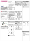
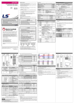
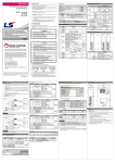
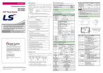
DATA SHEET LS Programmable Logic Controller XGB Positioning Module Safety Precautions ► Safety Precautions is for using the product safely and correctly in order to prevent the accidents and danger, so please go by them. ► The precautions explained here only apply to this module. For safety precautions on the PLC system, refer to User’s manual. ► The precautions are divided into 2 sections, ‘Warning’ and ‘Caution’. Each of the meanings is represented as follows. If you violate instructions, it can cause death, fatal injury or a XGB Warning considerable loss of property XBF-PD02A If you violate instructions, it can cause a slight injury or a slight loss of products Caution Handling Precautions ► Don’t drop or make impact. ► Don’t detach PCB from case. It may cause problem. ► When wiring, let no foreign material go into the module. If it goes into the module, remove it. ► Don’t detach the module from slot while power is on - When using LSIS equipment, thoroughly read this datasheet and associated manuals introduced in this datasheet. Also pay careful attention to safety and handle the module properly. - Store this datasheet in a safe place so that you can take it out and read it whenever necessary. ► Do not contact the terminals while the power is applied. Risk of electric shock and malfunction. 2 ► Protect the product from being gone into by foreign metallic matter. Risk of fire, electric shock and malfunction. 3 ► Risk of fire, electric shock and malfunction. Risk of injury and fire by explosion and ignition. 4 e-mail: [email protected] ► Tighten the screw of terminal block with the specified torque range. If the terminal screw is loose, it can cause fire and electric shock. LSIS Tokyo Office _ Tokyo, Japan Tel: 81-3-3582-9128 Fax: 81-3-3582-2667 . e-mail: [email protected] LSIS Shanghai Office _ Shanghai, China Tel: 86-21-5237-9977(609) Fax: 89-21-5237-7189 ► Use the PLC in an environment that meets the general specifications contained in this datasheet. Risk of electrical shock, fire, erroneous operation and deterioration of the PLC. e-mail: [email protected] ► Be sure that external load does not exceed the rating of output module. Risk of fire and erroneous operation. e-mail: [email protected] e-mail: [email protected] LSIS Chengdu Office _ Chengdu, China Tel: 86-20-8328-6754 Fax: 86-20-8326-6287 e-mail: [email protected] LSIS Europe B.V., Netherlands Tel: +31 (0)20 654 1420 Fax: +31(0)20 654 1429 e-mail: [email protected] Vibration resistance 6 Shocks resistance 7 Noise resistance ► Do not disassemble, repair or modify the PLC. Risk of electrical shock, fire and erroneous operation 9 10 11 Standard 0 ~ 55℃ - -25 ~ 70℃ - 5 ~ 95%RH, non-condensing - For discontinuous vibration Acceleration Amplitude Frequency times 10≤f∠57 Hz 0.075 mm 10 times in 57 ≤f≤150 Hz 9.8㎨ (1G) each For continuous vibration direction Acceleration Amplitude Frequency for 10≤f∠57 Hz 0.035 mm X, Y, Z 57≤f≤150 Hz 4.9㎨(0.5G) Max. impact acceleration : 147 ㎨ (15G) Authorized time : 11㎳ Pulse wave : Sign half-wave pulse (Each 3 times in X,Y,Z directions) Square wave AC: ±1,500V impulse noise DC: ±900V Electrostatic Voltage: 4kV (Contact discharge) discharge - Radiated electromagnetic field noise Fast transient /burst noise 8 Specification 5 ~ 95%RH, non-condensing Operating humidity Storage humidity 5 ► Do not use the PLC in the environment of direct vibration Risk of electrical shock, fire and erroneous operation. ► When disposing of PLC and battery, treat it as industrial waste. Risk of poisonous pollution or explosion. LSIS Qingdao Office _ Qingdao, China Tel: 86-532-8501-6068 Fax: 86-532-8501-6057 e-mail: [email protected] Item Operating temperature Storage temperature Caution ► Be sure to check the rated voltage and terminal arrangement for the module before wiring work. Risk of electric shock, fire and malfunction. Version V3.0 or above V1.8 or above V1.2 or above V3.1 or above 1. General Specifications 1 LSIS(ME) FZE _ Dubai, U.A.E. Tel: 971-4-886-5360 Fax: 971-4-886-5361 LSIS Guangzhou Office _ Guangzhou, China Tel: 86-20-8328-6754 Fax: 86-20-8326-6287 Applicable version For system configuration, the following version is necessary. Segment XBM-DxxxS type XBC-DxxxH type XEC-DxxxH type XG5000 No Warning HEAD OFFICE LS Tower, 127, LS-ro, Dongan-gu, Anyang-si,Gyeonggi-do, 431-848, Korea Tel: 82-2-2034-4870 Fax: (82-2)2034-4648 e-mail: [email protected] LSIS Beijing Office _ Beijing, China Tel: 86-10-5825-6027(666) Fax: 86-10-5825-6028 Revision History Date Version Updated Information 2009. 06 V1.0 1. First Edition 1. KOREAN/ENGLISH data sheet integrated 2. XEC Type of I/O area added 2011. 05 V3.0 3. Smart Link => I/O Link revised 4. CI Changed Ambient conditions Operating height Pollution degree Cooling type 80 ~ 1,000 MHz, 10 V/m Segment Power supply module Voltage 2 kV Digital/analog input/output communication interface 1 kV IEC61131-2 PLC Others PLC Interpolation Control method Control unit Positioning data Data preservation When power cut Positioning Position address Speed ACC/DEC process ACC/DEC time Max. output pulse Max. connection length Encoder input pulse Error indication Connection connector Size of wire Occupied points Consumption current (㎃) Weight(g) Performance specification 2 2 axis linear interpolation 2 axis circular interpolation Position, Speed, Speed/Position, Position/Speed Pulse 150 data areas for each axis (Step number 1~150) Can be set by XG5000 dedicated monitoring window or program Saves parameter, operation data at Flash memory Absolute/Incremental method -2,174,483,648 ~ 2,147,483,647 1 ~ 2,000,000(pulse/s) Trapezoid 0 ∼ 65,535 ㎳ (Can be selected among 4 ACC patterns and 4 DEC patterns) 2,000,000(pulse/s) 10m 200 kpps Indicated by LED 40 Pin connector WG #24 Fixed type: 64 point 500㎃ 65g Remarks 1) The number of Positioning module can be equipped with one basic unit is related with 5V power capacity of basic unit. Total consumption power of extension unit should be in the range of power capacity of basic unit. (1) Input specification Rated input Signal Voltage/ current DOG IEC61131-2 LSIS standard External High Limit External Low Limit IEC61131-2 IEC61000-4-2 In position IEC61131-2 IEC61000-4-3 IEC61131-2 IEC61000-4-4 No corrosive gas or dust - 2000m or less - 2 or less - Natural air cooling - Precautions for use Others Item Number of axis 3. External interface IO specification On Off Input Range of Respons voltage/cu voltage/cu resista voltage e time rrent rrent nce DC 24V/4.7㎃ DC 20.4∼26.4V DC 16V/3.1㎃ or above DC 4V/1.0㎃ or less DC 24V/4.7㎃ DC 20.4∼26.4V DC 16V/3.1㎃ or above DC 4V/1.0㎃ or less DC 24V/4.7㎃ DC 20.4∼26.4V DC 16V/3.1㎃ or abo e DC 4V/1.0㎃ or less DC 24V/4.7㎃ DC 20.4∼26.4V DC 16V/3.1㎃ or above DC 4V/1.0㎃ or less DC 5V/8㎃ DC4.25∼ 5.5 V DC 3V/3.5㎃ or above DC 1V/0.7㎃ or less About 5.1㏀ 0.7㎳ or less About 5.1㏀ About 5.1㏀ About 5.1㏀ about 670Ω 0.7㎳ or less 0.7㎳ or less 0.7㎳ or less 0.2㎳ or less Origin DC 4.25∼5.5 DC 3V/3.0㎃ DC 1V/1.0㎃ about 0.5㎲ or V or above or less 470Ω less Encoder input: Meets RS-422A Line Driver Level (Am26LS31) DC 5V/10㎃ Manual pulse generator /Encoder input ► Do not Install other places except PLC controlled place. ► Make sure that the FG terminal is grounded with class 3 grounding which is dedicated to the PLC. Otherwise, it can cause disorder or malfunction of PLC PLC 2. Performance Specifications Positioning ► The symbols which are indicated in the PLC and User’s Manual mean as follows. This symbol means paying attention because of danger of injury, fire, or malfunction ► This symbol means paying attention because of danger of electric shock. Store this datasheet in a safe place so that you can take it out and read it whenever necessary. Always forward it to the end user Related Manual Read this data sheet carefully prior to any operation, mounting, installation or start-up of the product. Name Number Name Number XG5000 10310000746 XGB hardware (IEC) 10310000981 (For XGI/XGR/XEC) XG5000 10310000511 XGB Analog 10310000862 (For XGK/XGB) XGI/XGR/XEC instruction 10310000739 XGB FEnet I/F 10310000854 XGK/XGB instruction 10310000509 XGB Cnet I/F 10310000736 XGB hardware 10310000893 XGB positioning module 10310001007 Others Homepage: http://eng.lsis.biz A) Best LS constantly endeavors to improve our products so that information in this datasheet is subject to change without notice. The date of issue: 2011. 5 10310001006 Ver 3.0 (2) Output specification Rated load voltage Signal Deviation count clear Pulse output DC 5~24V Load vol age range DC 4.75∼26.4V Max. load Max. voltage Leakage current Respon drop when current /Inrush se time On when Off current 0.1A(1 point) /0.4A 10㎳ or less DC 1V or less (rating) DC 2.5V or less (max.) 0.1㎃ or less 0.1㎳ or less ▷Differential line driver meeting Am26C31 ▷CW/CCW type, PLS/DIR type can be selected program and I/O parameter of XG5000 ▷pulse output mode, relation with pulse output level is as follows. ► ► ► ► ► C) Bad B) Good Connect expansion connector correctly when expansion module is needed. Do not detach PCB from the case of the module and do not modify the module. Turn off power when attaching or detaching module. Cellular phone or walkie-talkie should be farther than 30cm from the PLC. Input signal and communication line should be farther than 10cm from a hightension and a power line in order not to be affected by noise and magnetic field. (3) Interface when you use I/O link board 7. I/O area Wiring can be easy by connecting I/O link board and I/O connector when using XGB positioning module Available I/O link board and I/O cable is as follows (1) XBC/XBM Type Signal direction: PLC CPU positioning module Input signal Contents I/O link Name No. of pin TG7-1H40S 40 Name C40HH-10SB-XBI 9. Dimension (㎜) Connection cable Length Description 1m To connect extension module(40Pin) Uxy.00.0 ~ Uxy.00.E Not used Uxy.00.F Positioning module operation ready When wiring XGB positioning module by using TG7-1H40S and C40HH-10SB-XBI, relation between each terminal of I/O link board and I/O of positioning module is as follows. (2) XEC Type Signal direction: PLC CPU positioning module Input signal Contents %UXx.y.0 ~ %UXx.y.14 Not used %UXx.y.15 Positioning module operation ready 4. Parts Name and Descriptions (1) Name of each part 5. Wiring (1) Connection length between positioning module and driver device is max. 10m. But there is some difference according to specification of driver device. (2) When wiring I/O, avoid power ling and main circuit line. (3) Let the length of connection cable as short as possible. (4) Separate AC line and external I/O signal of positioning module so that I/O signal is not affected by surge or induction noise generated at AC line. (5) Use stable power as external power (DC5V, DC24V). (6) When wiring, if wire is close to high temperature device or contacts with oil, it may be the reason of short 6. Dedicated instruction No. Name ① Operation indication LED ② ③ Contents 1. RUN : On when power is supplied 2. X_AXIS, Y_AXIS ▶On: Now Running ▶Flickering: relevant axis error Connector Connector to connect with Driver, mechanical nput, manual for external pulse generator, etc. wiring O/S mode Dip switch for setting operation or O/S download mode dip switch (2) Interface with external Pin No. Item X Signal Y B20 A20 B19 A19 Function for each axis Manual pulse generator Encoder A+ input Manual pulse generator MPG AEncoder A- input Manual pulse generator MPG B+ Encoder B+ input Manual pulse generator MPG BEncoder B- input FP+ Pulse output (differential +) FPPulse output (differential -) RP+ Pulse sign (differential +) RPPulse sign (differential -) 0V+ High limit 0VLow Limit DOG DOG MPG A+ A18 A17 A16 A15 A14 A13 A12 A11 A10 A9 A8 A7 A6 A5 B18 B17 B16 B15 B14 B13 B12 B11 B10 B9 B8 B7 B6 B5 A4 B4 A3 A2 A1 B3 B2 B1 NC COM NC INP INP COM CLR CLR COM HOME +5V HOME COM NC Signal direction module external Not used Common(OV+,OV-,DOG) Not used In position signal DR/INP signal Common Deviation counter clear signal Deviation counter clear signal Common Origin signal (+5V) Origin signal (+5V) Common Not used ⇔ ⇔ ⇔ ⇔ Type instruction 1 Module information SRD Reads operation status Level TBP TCP THP TSP ORG DST IST LIN CIN SST Sets basic parameter Sets common parameter Sets homing parameter Sets I/O signal parameter Starts homing Direct start Indirect start Linear interpolation Circular interpolation Synchronous start Edge INCH Inching operation SSP SSS POR SOR PSO VTP PTV SNS SRS STP TEA TEAA TWR TMD WRT CLR EPRS EMG MOF PRS FLT Position synchronization Speed synchronization Position override Speed override Speed override at specific position Speed/Position conversion Position/speed conversion Changes start step number Changes repetition step number Deceleration stop Single teaching Multiple teaching Sets multiple teaching data Sets operation data Saves parameter/operation data Error reset Encoder preset Emergency stop Cancels M code Current position preset Sets floating origin 2 3 4 5 6 7 8 9 10 11 12 13 14 15 16 17 18 19 20 21 22 23 24 25 26 27 28 29 30 31 32 33 Parameter Auto operation Manual operation Subsidiary operation Teaching Data error Encoder others contents Operation condition No. Edge Signal direction: PLC CPU positioning module Output signal Contents Uxy.01.0 X forward JOG Uxy.01.1 X reverse JOG X JOG LOW speed/HIGH speed Uxy.01.2 Uxy.01.3 Y forward JOG Uxy.01.4 X complete signal clear Uxy.01.5 Y reverse JOG Y JOG LOW speed/HIGH speed Uxy.01.6 Uxy.01.7 Y complete signal clear Uxy.01.8 ~ Uxy.01.F Not used Signal direction: PLC CPU positioning module Output signal Contents %UXx.y.16 X forward JOG %UXx.y.17 X reverse JOG %UXx.y.18 X JOG LOW speed/HIGH speed %UXx.y.19 Y forward JOG %UXx.y.20 X complete signal clear %UXx.y.21 Y reverse JOG %UXx.y.22 Y JOG LOW speed/HIGH speed %UXx.y.23 Y complete signal clear %UXx.y.0 ~ %UXx.y.14 Not used 8. Initial installation and parameter setting This section explains the initial installation and parameter setting method of APM (Advance Positioning Module). The following procedures should be followed in order. (1) Wire the pulse output terminal of positioning module and the pulse input terminal of motor drive. Refer to the motor drive user’s manual for the accurate wiring. (2) Connecting input signal terminal is not necessary for the initial setting and test. (3) Connect to positioning module through XG5000. (Refer to the user’s manual for the usage of XG5000.) (4) Open a new file after connection. (5) Use the monitoring function of the XG5000 to check the input signals on the external signal window. All input signals are displayed as Off. (6) The settings of the pulse output mode of basic parameter in XG5000 and pulse input mode of motor drive are identical. Refer to driver’s user manual and confirm the current pulse input mode of motor drive. Thereafter set all input signal parameters as A contact point. (7) Download the parameters and operating data using Data Read/Write of XG5000 monitoring window. If downloading is not performed, the parameters and operating data will not be set. (8) After completing download, execute the JOG operation to check the forward and reverse operation. Error should not be expected, but if it occurred, take proper measures. (9) If the motor does not operate and the operation displayed on the monitoring window is normal, execute 8) after confirming 1), 6), and 7). It happens if the wiring of pulse output terminal or setting of pulse output mode in basic parameter is incorrect. (Sometimes, because of parameter setting state of motor drive, it may not operate. If the wiring of motor drive and pulse output mode are normal, check the parameter settings of motor drive.) (10) If motor operates normally, wire the external input signals according to the system configuration. Set and download the proper operating data and parameters in the XG5000. (The state of the external input signals can be checked in the external signal window.) (11) High limit, lower limit, Inposition signal doesn’t operate normally when operation condition doesn’t coincide with setting of I/O signal. So consider operation condition (12) Make a program according to the system configuration using XG5000. Remarks 1) For the test operation in monitoring window, change the CPU in STOP mode because the program could affect the test operation. 10. Warranty (1) Warranty period LSIS provides an 18-month-warranty from the date of the production. (2) Warranty conditions For troubles within the warranty period, LSIS will replace the entire PLC or repair the troubled parts free of charge except the following cases. (a) The troubles caused by improper condition, environment or treatment except the instructions of LSIS. (b) The troubles caused by external devices. (c) The troubles caused by remodeling or repairing based on the user’s own discretion. (d) The troubles caused by improper usage of the product. (e) The troubles caused by the reason which exceeded the expectation from science and technology level when LSIS manufactured the product. (f) The troubles caused by natural disaster. (3) This warranty is limited to the PLC itself only. It is not valid for the whole system which the PLC is attached to.