Transcript
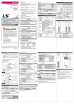
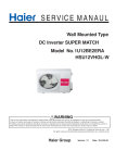
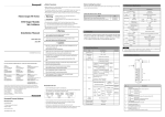
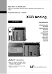
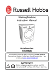
DATA SHEET LS Programmable Logic Controller RTD Input Option Board XGB Safety Precautions ► Safety Precautions is for using the product safely and correctly in order to prevent the accidents and danger, so please go by them. ► The precautions explained here only apply to this module. For safety precautions on the PLC system, refer to User’s manual. ► The precautions are divided into 2 sections, ‘Warning’ and ‘Caution’. Each of the meanings is represented as follows. If you violate instructions, it can cause death, fatal injury or a Warning considerable loss of property XBO-RD01A Caution If you violate instructions, it can cause a slight injury or a slight loss of products ► The symbols which are indicated in the PLC and User’s Manual mean as follows. This symbol means paying attention because of danger of injury, fire, or malfunction ► This symbol means paying attention because of danger of electric shock. Store this datasheet in a safe place so that you can take it out and read it whenever necessary. Always forward it to the end user Related Manual Read this data sheet carefully prior to any operation, mounting, installation or start-up of the product. Na e Code XG5000 User’s manual(Programming software) 10310000512 XGK Basic Instruction & Programming User’s manual 10310000510 XGB Series user’s manual 10310000694 XGB Hardware 10310000893 Revision History Date 2011.03 2011.05 Version V1.0 V1.1 Updated Information First Edition CI changed Applicable version For system configuration, the following version is necessary. Segment XGB E type XGB S type XGB SU type XG5000 Item Number of channel Input PT100 sensor JPT100 type Input PT100 temp. JPT100 range PT100 Digital output JPT100 Precision Max. Conversion speed Insulation method Terminal block I/O occupation point Sensor wiring method Averaging function Additional function Alarm function Consumption Internal current DC5V Weight Version V1.11 or above V1.11 or above V1.0 or above V3.61 or above Handling Precautions ► Don’t drop or make impact. ► Don’t detach PCB from case. It may cause problem. ► When wiring, let no foreign material go into the module. If it goes into the module, remove it. ► Don’t detach the module from slot while power is on - When using LSIS equipment, thoroughly read this datasheet and associated manuals introduced in this datasheet. Also pay careful attention to safety and handle the module properly. - Store this datasheet in a safe place so that you can take it out and read it whenever necessary. 2. Performance Specifications Performance specification 1 channel JIS C1604-1997 JIS C1604-1981 , KS C1603-1991 -200 ~ 600℃ -200 ~ 600℃ -2000 ~ 6000 -2000 ~ 6000 ±1.0% or less 25ms – Note1) Non-insulation between input terminal and PLC basic unit 5-point terminal block Fixed type: 64 point 3-line type Count-averaging process function Detection of disconnection 30mA 20g Remarks Note1) Conversion speed may be delayed because of scan delay of XGB main module. Warning ► Do not contact the terminals while the power is applied. Risk of electric shock and malfunction. ► Protect the product from being gone into by foreign metallic matter. Risk of fire, electric shock and malfunction. ► Risk of fire, electric shock and malfunction. Risk of injury and fire by explosion and ignition. 1. General Specifications HEAD OFFICE LS Tower, 127, LS-ro, Dongan-gu, Anyang-si,Gyeonggi-do, 431-848, Korea Tel: 82-2-2034-4870 Fax: (82-2)2034-4648 e-mail: [email protected] Caution ► Be sure to check the rated voltage and terminal arrangement for the module before wiring work. Risk of electric shock, fire and malfunction. LSIS(ME) FZE _ Dubai, U.A.E. Tel: 971-4-886-5360 Fax: 971-4-886-5361 e-mail: [email protected] ► Tighten the screw of terminal block with the specified torque range. If the terminal screw is loose, it can cause fire and electric shock. LSIS Tokyo Office _ Tokyo, Japan Tel: 81-3-3582-9128 Fax: 81-3-3582-2667 . e-mail: [email protected] LSIS Shanghai Office _ Shanghai, China Tel: 86-21-5237-9977(609) Fax: 89-21-5237-7189 ► Use the PLC in an environment that meets the general specifications contained in this datasheet. Risk of electrical shock, fire, erroneous operation and deterioration of the PLC. e-mail: [email protected] LSIS Beijing Office _ Beijing, China Tel: 86-10-5825-6027(666) Fax: 86-10-5825-6028 ► Be sure that external load does not exceed the rating of output module. Risk of fire and erroneous operation. e-mail: [email protected] ► Do not use the PLC in the environment of direct vibration Risk of electrical shock, fire and erroneous operation. LSIS Guangzhou Office _ Guangzhou, China Tel: 86-20-8328-6754 Fax: 86-20-8326-6287 e-mail: [email protected] LSIS Chengdu Office _ Chengdu, China Tel: 86-20-8328-6754 Fax: 86-20-8326-6287 ► Do not disassemble, repair or modify the PLC. Risk of electrical shock, fire and erroneous operation No 1 2 3 4 5 6 ► When disposing of PLC and battery, treat it as industrial waste. Risk of poisonous pollution or explosion. e-mail: [email protected] LSIS Qingdao Office _ Qingdao, China Tel: 86-532-8501-6068 Fax: 86-532-8501-6057 e-mail: [email protected] LSIS Europe B.V., Netherlands Tel: +31 (0)20 654 1420 Fax: +31(0)20 654 1429 e-mail: [email protected] Precautions for use ► Do not Install other places except PLC controlled place. ► Make sure that the FG terminal is grounded with class 3 grounding which is dedicated to the PLC. Otherwise, it can cause disorder or malfunction of PLC PLC Others PLC Others PLC LS constantly endeavors to improve our products so that information in this datasheet is subject to change without notice. The date of issue: 2011. 5 10310001191 Ver 1.1 3. Parts Names and Descriptions 35.0mm ① Hook for fixation 49.0mm ② Terminal block ③ Cover ④ Hook for fixation ⑤ Connector for option board ⑥ Input connector Name ► ► ► ► ► Connect expansion connector correctly when expansion module is needed. Do not detach PCB from the case of the module and do not modify the module. Turn off power when attaching or detaching module. Cellular phone or walkie-talkie should be farther than 30cm from the PLC. Input signal and communication line should be farther than10cm from a hightension and a power line in order not to be affected by noise and magnetic field. - 5 ~ 95%RH, non-condensing - 5 ~ 95%RH, non-condensing - For discontinuous vibration Frequency Acceleration Amplitude times 10≤f∠57 Hz 0.075 mm 10 times Vibration 57 ≤f≤150 Hz 9.8㎨ (1G) in each resistance For continuous vibration direction Frequency Acceleration Amplitude for 10≤f∠57 Hz 0.035 mm X, Y, Z 57≤f≤150 Hz 4.9㎨(0.5G) Max. impact acceleration : 147 ㎨ (15G) Shocks Authorized time : 11㎳ resistance Pulse wave : Sign half-wave pulse (Each 3 times in X,Y,Z directions) Square wave AC: ±1,500V impulse noise DC: ±900V Electrostatic 4kV (Contact discharge) discharge electromagnetic Noise field noise resistance ▶Terminal block for connecting external RTD temperature sensor ③ Cover ▶Option board cover 9 10 11 Ambient conditions Operating height Pollution degree Cooling type Connection example B *1 b 2-line type NC NC *2 Connector for ▶Connection connector for connecting the option board option board to the basic unit ▶Wiring connector for connecting with the external Input connector device FG A LSIS standard IEC61131-2 IEC61000-4-2 Digital/analog input/output communication interface 1 kV IEC61131-2 IEC61000-4-4 - 2 or less - Natural air cooling - (1) Conversion data I/O area (U device) Wiring IEC61131-2 2000m or less 5. Internal memory 6. Dimension (㎜) Variable Type Device Comment _0x_ERR _0x_RDY _0x_CH0_ACT _0x_CH0_BOUT Bit Bit Bit Bit U0x.00.0 U0x.00.F U0x.01.0 U0x.01.4 Module error Module Ready CH 0 running CH 0 disconnection CH 0 temp. conversion value _0x_CH0_TEMP Word IEC61131-2 No corrosive gas or dust (1) Precautions for wiring (a) Don’t let AC power line near to RTD input option board’s external output signal line. With an enough distance kept away between, it will be free from surge or inductive noise. (b) Don’t let the cable too close to hot device and material or in direct contact with oil for long, which will cause damage or abnormal operation due to short-circuit. (c) Wiring with high-voltage line or power line may produce inductive hindrance causing abnormal operation or defect. (2) Wiring example (a) There are three types of wiring method to connect Pt100 or JPt100 to RTD input option board (2-line type, 3-line type and 4-line type) (b) For the wire used when Pt100 or JPt100 is away from the RTD input option board, resistance of the wire should be 10Ω or less per one wire. And wires for each channel should be same (thickness, length, type and etc.) (c) The gap between wires used for channels should be 1Ω or less. Otherwise, it may not meet the precision indicated at 3. performance specification. 2 kV - IEC61131-2 IEC61000-4-3 80 ~ 1,000 MHz, 10 V/m 4. Wiring Description Terminal block ⑥ - -25 ~ 70℃ Power Fast transient Segment supply module burst noise 8 C) Bad B) Good Hook for fixation ▶Hook for fixing the option board to basic unit ② ⑤ Operating humidity Storage humidity Others A No. Standard 0 ~ 55℃ Voltage A) Best ①,④ Specification Radiated 7 Homepage: http://eng.lsis.biz 10.3mm Item Operating temperature Storage temperature U0x.04 Signal Read/Write direction Read Option → CPU Remarks How to express U device U0x.00.0 Bit no. Slot Word no. Ex1) CH0 temp. conversion value of the module at slot 9 -> U09.04 Ex2) CH0 disconnection flag of the module at slot 9 -> U09.01.4 (2) Operation parameter setting area Address Contents Setting value Read/Write Instruction Enable CH 0 Enable CH 0: Disable 1: Enable Sensor type setting PUT 1 Sensor type setting 0: PT100 Read/Write GET 1: JPT100 Data type setting 5 Temp. unit setting 0: Celsius 1: Fahrenheit Disconnection 0: Normal 6 Read GET information 1: Disconnection CH0 count average PUT 14 0 or 2~64,000 Read/Write setting GET 100: Sensor type setting 15 Error information error Read GET 300: Average setting error B b 3-line type NC *1 NC *2 FG 7. Warranty A B b 4-line type NC *1 NC *2 Remarks *1 : RTD (Pt100 or JPt100) *2 : shield line – Connect the shield of RTD and wire to FG. FG (1) Warranty period LSIS provides an 18-month-warranty from the date of the production. (2) Warranty conditions For troubles within the warranty period, LSIS will replace the entire PLC or repair the troubled parts free of charge except the following cases. (a) The troubles caused by improper condition, environment or treatment except the instructions of LSIS. (b) The troubles caused by external devices. (c) The troubles caused by remodeling or repairing based on the user’s own discretion. (d) The troubles caused by improper usage of the product. (e) The troubles caused by the reason which exceeded the expectation from science and technology level when LSIS manufactured the product. (f) The troubles caused by natural disaster. (3) This warranty is limited to the PLC itself only. It is not valid for the whole system which the PLC is attached to.