1
1 0 . Data Output Format
10.1 General
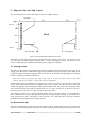
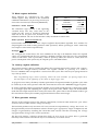
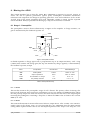
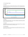
The output from the APV6 is in current form and in the range of 0 to +600uA. The output of the chip is
approximately zero when there is nothing to transfer, but, when an event has been triggered data is
output in the form shown in Figure 11. A data set is made up of three parts, a digital header, address
and an analogue data set.
600
Output Current (uA)
500
400
300
4 bit header
128 analogue levels
200
100
0uA
Address
7.0 microseconds
Time
Figure 11: APV6 output data format
10.2 Header
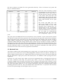
Four logic samples, should all be high, i.e. 15uA. If an error is sensed by the APV6 internal watchdog
logic the second sample is switched low. This is so that erroneous data packets in the DAQ can be
identified and reported to the control system
10.3 Address
An 8-bit number which defines the column address that was used to store the samples in the analogue
memory, this can be used to monitor the synchronicity of many chips and as a tool to aid t h e
identification and removal of data from “bad” memory locations.
10.4 Analogue data
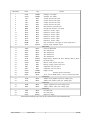
128 samples of analogue data, where a MIP equivalent signal should be represented by a current of
50uA. The baseline offset may be adjusted (VADJ) to give optimal dynamic range in the signal
polarity in which a chip is working.
apv6_manual.doc
Version: Draft
21
16/10/96