1
Mobile Robot chapter 5: Peripheral devices and programming experiments (v.2a)
8031 SBC
8031
CPU
Parallel
Ports
Two
8255
Watch
-dog
timer
AMX
691
48 digital
IO pins
Real-time clock
DS1287A
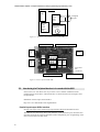
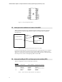
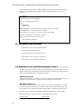
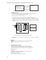
Figure 5. 1 An overview of peripheral devices of the SBC
GAL 18GV8
MAX691 watchdog timer
RS232
LEDs
EPROM
8255
8255
8031
MAX23
SRAM
SRAM
RTC
7805 regulator
Two 8255
bus
connectors
LCD CONNECTOR
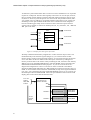
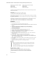
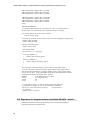
Figure 5. 2 Picture of the 8031RL SBC
5.3. Introducing the Peripheral devices to be used with the 8031
In this section we will discuss the ways of how to use a number of different useful
peripheral chips for the 8031, and illustrate how to utilize these devices through a series
of experiments.
Datasheets of these chips can be found at
http://www.cse.cuhk.edu.hk/~khwong/datasheets
Parallel input/output 8255s interface
See http://developer.intel.com/design/periphrl/INDEX.HTM for datasheet of 8255.
The SBC has two 8255 chips. Since each 8255 has 3 sets of 8-bit IO pins, therefore each
8255 has 24-bit IO bits. Thus the board has 48 bits of digital IO pins. Programming of the
8255 can be found in the data sheet.
2