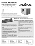
1
AeroCool™
Evaporative Cooling System
123456789012345678901234567890121234567890123
123456789012345678901234567890121234567890123
123456789012345678901234567890121234567890123
123456789012345678901234567890121234567890123
CRxx Series
123456789012345678901234567890121234567890123
USER'S MANUAL and INSTALLATION GUIDE
TABLE OF CONTENTS
Section
Page
Unpacking the Cooling System .............................................................................................. 2
Installation ............................................................................................................................ 2-12
Plumbing ............................................................................................................................. 13-16
Flush Out Kit (EC1506) purchased separately ...................................................................... 17
System Start-Up .................................................................................................................... 17
System Operation and Adjustment ........................................................................................ 17
Maintenance .......................................................................................................................... 18
Maintenance Checklist .......................................................................................................... 18
Warranty ................................................................................................................................ 18
Exploded View and Parts List .............................................................................................. 19-20
THANK YOU
Thank you for purchasing an Aerotech, Inc. Evaporative Cooling System. Aerotech equipment is
designed to be the highest performing, highest quality equipment you can buy. With the proper
installation and maintenance it will provide many years of service.
PLEASE NOTE
To achieve maximum performance and insure long life from your Evaporative Cooling System it is
essential that it be installed and maintained properly. Please read all instructions carefully before
beginning installation.
AEROTECH, INC.
4215 Legion Dr. Mason, MI 48854-1036 USA
(517) 676-7070 Fax (517) 676-7078
FORM: QM1127
Rev. 6, April 2000
Page 1 of 20
UNPACKING THE EQUIPMENT
Before beginning installation, check the overall condition of the equipment. Remove packing materials, and
examine all components for signs of shipping damage. Any shipping damage is the customer's responsibility
and should be reported immediately to the freight carrier.
61/8"
Pad Height
Pad Height + 4"
8 1 /4 "
101/4"
NOTE: EC1600 (for non-submersible pumps) or
EC1601 or EC1605 (for submersible pumps) must
be purchased with each 'CR' Cooling System
Pad Height + 133/4"
11/ 2"
Each CR-System includes:
10" Pipe, PVC
Drip Collector, PVC
Distribution Cap, Aluminum
Pad Retainer, Aluminum
11/4" Pipe with holes, PVC
11/4" Slip Cap, PVC
2 - End Panels, left / right, Plastic
Evaporative Cooling Pad
Pipe Support Brackets - supplied for
4' O.C. (see Chart A)
1 - Hardware Package
1 - Flush Out Kit (EC1506), purchased separately
105/8"
INSTALLATION INSTRUCTIONS
1) Construct a wall opening according to your cooling system size, with studs
4' O.C. (max 5' O.C.). See Figure 1. (For example a CR36 with EC1115
would have an opening of 36' 1/2" L. x 64" H.).
Figure 1
48"
Catalog
No.
Pad
Height
EC1101
EC1102
EC1103
EC1115
EC1104
24"H
36"H
48"H
60"H
72"H
48" O.C. Typical
Double 2 x 4 Treated Framing
(Install Level)
Pad Height + 4"
Pad Height + 4"
Double
2x4
Treated
Framing
Pad Length + ½"
101/4"
2"
1 x 6 Treated
Framing
1 x 4 Treated
Framing
101/4"
Extra Stud
or Post for
Left or Right
end Framing
(if necessary)
AEROTECH, INC.
4215 Legion Dr. Mason, MI 48854-1036 USA
(517) 676-7070 Fax (517) 676-7078
Wall Studs
See
Chart A
1 x 6 Treated Framing
1 x 4 Treated Framing (Install Level)
FORM: QM1127
Rev. 6, April 2000
Page 2 of 20
2) For proper pipe support bracket spacing refer to Chart A, Figures 2A and 2B.
Chart A
Length of
Cooling
System
4'
6'
8'
10'
12'
14'
16'
18'
20'
22'
24'
26'
28'
30'
32'
34'
36'
38'
No of
Brackets
Needed
Placement of
Brackets*
2
2
2
3
3
4
4
5
5
6
6
7
7
8
8
9
9
10
1'
1'
2'
1'
2'
1'
2'
1'
2'
1'
2'
1'
2'
1'
2'
1'
2'
1'
Length of
Cooling
System
No of
Brackets
Needed
Placement of
Brackets*
40'
42'
44'
46'
48'
50'
52'
54'
56'
58'
60'
62'
64'
66'
68'
70'
72'
10
11
11
12
12
13
13
14
14
15
15
16
16
17
17
18
18
2'
1'
2'
1'
2'
1
2'
1'
2'
1'
2'
1'
2'
1'
2'
1'
2'
IMPORTANT!
The tee and cap must
be evenly setting on
the ground or supported securely on a
level surface.
*Placement feet from each end
NOTE: If framing for the pipe support brackets is different than shown in Figure 2A and 2B order
additional pipe support brackets (EC1325) and pipe support brace kit (EC1625).
Figure 2A
24"
48"
48" O.C.
typical
24"
Tee and Cap setting on ground or level surface
Figure 2B
12"
48"
48" O.C.
typical
12"
Tee and Cap setting on ground or level surface
AEROTECH, INC.
4215 Legion Dr. Mason, MI 48854-1036 USA
(517) 676-7070 Fax (517) 676-7078
FORM: QM1127
Rev. 6, April 2000
Page 3 of 20
3) At the bottom fasten the Pipe Support Bracket on the post (stud), necessary for spacing from Chart A, flush
with top of 1 x 6 at a maximum of 5' O.C. with 3/8" x 31/2" Lag screws (provided). Pre-drill framing for Lag
screws using 1/4" drill bit. See Figure 3A and 3B. If framing does not match Figure 3A, framing must be
capable of supporting 50-60 lbs. per foot.
48"
48" O.C. Typical
Double 2 x 4 Treated Framing
Pad Height + 4"
Pad Height + 4"
Double
2x4
Treated
Framing
101/4"
Pad Length + ½"
Pipe Support
Bracket
Extra Stud
or Post for Left or
Right end Framing
(if necessary)
Enclose area
between
1 x 6 and 1 x 4 to
make air tight
Pipe Support
Bracket
1 x 6 Treated Framing
1 x 4 Treated Framing
Figure 3A
1 x 6 Treated
Framing
3 8
/ " x 31/2" Lag Screw
101/4"
Wafer Head Bolt
Nut
Enclose area
between
1 x 6 and 1 x 4
to make air
tight
Support Brace
1 x 4 Treated
Framing
Figure 3B
4) With small hole in Support Brace against bottom of Pipe Support Bracket, fasten together using (1) Wafer
Head Bolt and Nut (provided), tighten. Be sure that the wafer head bolt is fully seated into countersink of
bracket. See Figure 3B.
5) Fasten Support Brace to the 1 x 4 with (1) 3/8" x 31/2" Lag screw (provided). Use the pre-drilled hole in the
brace. Pre-drill framing for Lag screw using 1/4" drill bit. See Figure 3B. Enclose the area between the 1 x 6
and 1 x 4 to make air tight.
AEROTECH, INC.
4215 Legion Dr. Mason, MI 48854-1036 USA
(517) 676-7070 Fax (517) 676-7078
FORM: QM1127
Rev. 6, April 2000
Page 4 of 20
6) Cut a 3" notch on one side of the belled end of the
pipe to allow the male to slide in easier. Put
a mark on the male pipe 4" from the end. See
Figure 4. NOTE: may not need to cut if
temperature is above 85-90°. Can slide pipe up
to bell.
Belled end:
PVC Pipe
Primer and
Cement Inside
Male: PVC
Pipe Primer
and Cement
Outside
4"
7) First prepare the pipe with PVC Pipe Primer, following
directions of use and drying. After priming, use 'Rain
or Shine' type of PVC cement in accordance to PVC
cement directions.
8) Position first 2 sections of pipe in Pipe Support Brackets. Prior
to assembly apply a generous amount of PVC cement to the
inside of the belled end, and the outside of the male end. See
Figure 4.
9) While aligning the notch and mark, insert the male end into the
belled until the mark meets the edge of the belled pipe
(approximately 4"). See Figure 5. Position next section of pipe
in Pipe Support Bracket and continue assembly by repeating
Steps 6 - 9 until complete. Making sure to keep all the notches
aligned.
10) Allow the PVC cement to dry fully, based on the PVC cement
directions (minimum of 2 hours).
3" Notch
Figure 4
4"
Figure 5
11) After PVC cement has fully dried, use a level to find the top,
center of the pipe at end of each pipe section and mark it with
a permanent black felt marker (marks should not be more than
12' O.C.). Then use a chalk line or a piece of the aluminum
pad retainer as a straight edge to draw a line between the
marks. See Figure 6. Measure 71/4" down from the original
marks and draw another line. See Figure 7.
Level
Pipe
7 1 /4 "
Pipe
Pipe
Support
Bracket
Support
Brace
Support
Brace
Pipe
Support
Bracket
Figure 7
Figure 6
Mark on top of Pipe
NOTE:
PVC cement must be completely dried before cutting takes place. Failure to do so may
result in pipe sections coming apart.
AEROTECH, INC.
4215 Legion Dr. Mason, MI 48854-1036 USA
(517) 676-7070 Fax (517) 676-7078
FORM: QM1127
Rev. 6, April 2000
Page 5 of 20
12) Starting on the end that the tee will mount on, measure 7" from the end of the pipe and place a mark on both
lines drawn in Step 11. From these marks, measure a distance equal to the pad length of the system. The
remaining length of pipe may be longer than 7" or can be cut down to no less than 7". Draw a line between
these marks to form the end of slot to be cut. See Figure 8. Using a circular saw, cut one of the long marked
lines. (Cut the end lines last.) While cutting the first line insert a screwdriver into the cut 18" to 24" behind the
saw to keep the cut from pinching and stalling the circular saw. Then cut the remaining lines. See Figure 8.
Clean out saw dust from bottom of pipe.
Cut Pattern
Length of Pad
7" Minimum
7" Minimum
Figure 8
13) Insert drip collector into opening of pipe and fasten one side only using #10 x 3/4" TEK screws every 15" for
the entire length. Use the 'V' notch in the drip collector to align the screws. See Figure 9.
#10 x 3/4"
TEK Screw
15"
Screw location
'V' Notch
Figure 9
14) While one person holds the end of the pipe and drip
collector level, have another person twist the pipe
and drip collector to its level position and fasten the
remaining side with #10 x 3/4" TEK Screws every 15"
O.C. See Figures 9 and 10. Continue installing drip
collector until fully installed by repeating
Steps 13 & 14, leaving no gap between collectors
(press sections tightly together).
Drip Collector
Pipe Reservoir
1 x 6 Treated Framing
Pipe Support
Bracket
Support Brace
Figure 10
AEROTECH, INC.
4215 Legion Dr. Mason, MI 48854-1036 USA
(517) 676-7070 Fax (517) 676-7078
FORM: QM1127
Rev. 6, April 2000
Page 6 of 20
15) Prepare the tee, pipe nipples and pipe cap in accordance to
PVC primer and cement directions and assemble the (2)
pipe nipples, tee and pipe cap. See Figure 11A. See Figure
11B, C for assembly completion.
13" Pipe Nipple
Tee
28" Pipe Nipple
Pipe Cap
Figure 11A
15" x 15"L. Pipe Cap
10" x 13"L. Pipe Cap
15" Tee
10" Tee
10" x 13"L. Pipe
10 - 45° Elbow
15" x 28"L. Pipe
10" x 28"L. Pipe
15" Slip Cap
10" Slip Cap
Figure 11B
EC1600 AND EC1601
(COMPLETED)
AEROTECH, INC.
4215 Legion Dr. Mason, MI 48854-1036 USA
(517) 676-7070 Fax (517) 676-7078
Figure 11C
EC1605
(COMPLETED)
FORM: QM1127
Rev. 6, April 2000
Page 7 of 20
16) Once the PVC cement has dried use primer and cement and assemble the tee fully onto pipe. Be sure the
drip collectors remain on top and the tee is straight up and down. When tee is completely installed the 28"
pipe nipple with cap may be buried so that when together it rests on the ground or another support. See
Figure 11D and 11E.
IMPORTANT!
The tee and cap must be evenly setting on the
ground or supported securely on a level surface.
13" Pipe Nipple
Tee
28" Pipe Nipple
Pipe with Drip Collectors
Figure 11D
PIPE CAP BURIED
Pipe Cap
13" Pipe Nipple
Tee
28" Pipe Nipple
Pipe with Drip Collectors
Figure 11E
PIPE CAP ON GROUND
AEROTECH, INC.
4215 Legion Dr. Mason, MI 48854-1036 USA
(517) 676-7070 Fax (517) 676-7078
Pipe Cap
FORM: QM1127
Rev. 6, April 2000
Page 8 of 20
17a) Determine the height of your cooling system and cut the end panels down to the correct length according to
Chart B. Trim the end panels as indicated below. Determine which end panel will be at the end with the
water supply and drill a 13/4" - 2" dia. hole 17/8" from top, as shown. If the EC1506 Flush-Out Kit was
purchased, then drill a 13/4" - 2" dia. hole in the other end panel also. See Figure 12A.
Pad
Height
Length of
End Panel
V-Groove Guide for center of hole
1 4
24"H
36"H
48"H
60"H
72"H
27 / "
391/4"
511/4"
631/4"
751/4"
17/8"
13/4" - 2" Dia. hole for Water
Supply or Flush Out Kit
43/ 4"
Rib to be trimmed
Chart B
17/8"
Length of End Panel
4 3 /4 "
Rib to be trimmed
Rib to be trimmed
1 1 /2 "
RIGHT END PANEL
3
/ 4"
Rib
to be
trimmed
Figure 12A
11/2"
11/2"
3
LEFT END PANEL
/4"
17b) Slide end panel into notch in pipe on left end. End panel should sit flat on drip collection, while holding the
end panel tightly in place attach it to the framing with #14 x 11/2" Lag screws (provided) See Figure 12B
and Chart C for spacing and number of lag screws provided.
#14 x 11/2" Lag Screw
End Panel
Pad
Height
No. of
Screws
Spacing
24"H
36"H
48"H
60"H
72"H
2
3
3
4
4
12"O.C.
18"O.C.
24"O.C.
18"O.C.
24"O.C.
Chart C
Double 2 x 4
Treated Framing
Drip Collector
V-Groove
Figure 12B
AEROTECH, INC.
4215 Legion Dr. Mason, MI 48854-1036 USA
(517) 676-7070 Fax (517) 676-7078
FORM: QM1127
Rev. 6, April 2000
Page 9 of 20
NOTE:
PVC cement must be completely dried before filling system with water. Failure to do so may
result in pipe and tee sections coming apart.
18) Caulk around inside and outside of end panels where end panel meets drip collector and pipe. Also caulk
each drip collector joint.
19) Slide 6" stainless steel bolts into distribution cap and drive into position using hammer and punch. Bolts must
be completely seated in. See Figure 13A. Attach distribution cap to left end of framed opening using
#14 x 11/2" Lag screws. Be sure that the lag screws go in square so as not to tip cap upward. See Figure
13B & C.
20) Holding the left end panel tight to distribution cap, place the long side of the Angle Bracket on the end panel
and the short side on top of the distribution cap. See Figure 13C. Attach the angle bracket to the distribution
cap using (2) #10 x 3/4" TEK Screws (provided). Fasten angle bracket to end panel using (2) #10 x 3/4" TEK
Screws (provided).
21) Repeat Step 19 until you have installed all of the distribution caps.
Double 2 x 4 Treated Framing
Distribution Cap
#14 x 11/2" Lag Screw
Distribution Cap
6" Stainless
Steel Bolt
Figure 13A
6" Stainless Steel Bolt
Figure 13B
Distribution Cap
#10 x 3/4" TEK Screws
#10 x 3/4"
TEK Screws
Angle Bracket
#10 x 3/4"
TEK Screws
#14 x 11/2"
Lag Screw
Angle
Bracket
Left End Panel
#10 x 3/4"
TEK Screws
Left Side
2x4
Framing
AEROTECH, INC.
4215 Legion Dr. Mason, MI 48854-1036 USA
(517) 676-7070 Fax (517) 676-7078
Figure 13C
FORM: QM1127
Rev. 6, April 2000
Page 10 of 20
22) Slide pipe holders over distribution pipe, one for every 2' of pipe. See Figure 14A. The section of pipe with
the slip cap will go on the end opposite the supply / pump end. For systems longer than 12', connect sections
of pipe together keeping holes aligned. See Figure 14B. Position pipe and pipe holders in distribution cap on
stainless steel bolts. Rotate pipe so that holes are straight upward (12 o'clock). See Figure 14C.
Distribution Holder
Belled end of Pipe
Distribution Pipe
Pipe Holder
Slip Cap
Figure 14A
Figure 14B
23) Begin putting cooling pad in place, taking care to
position pieces so that the Directional Arrows are
pointing upward and to the inside of the building.
See Figure 15. Continue this pattern, stopping at
the next to the last piece of pad. Set the right end
panel in place (do not secure it).
Double 2 x 4 Framing
Distribution Cap
Distribution Hole in Pipe
24) While holding the right end panel tightly in place
slide the next to the last piece of pad into the end
panel. Measure the opening that is left for the last
piece of pad at the top and bottom of the opening.
If the opening is smaller than the width of the last
piece of pad, then using a hand saw trim the last
piece of cooling pad to fit the opening. Put the last
piece in place and secure the end panel to the framed
opening using the #14 x 1½" Lag screws. See Figure 16.
Attach the angle bracket to the distribution cap and right
end panel using (4) #10 x 3/4" TEK Screws (provided),
refer to Step 20.
Distribution Pipe
Pipe Holder
Figure 14C
Measure at the top
6" Stainless Steel Bolt
Angle Bracket
#10 x 3/4"
TEK Screws
Distribution Cap
Right End Panel
Next to the last
piece of Cooling
Pad
Cooling Pad
Left
End
Panel
Drip Collector
Double
2x4
Treated
Framing
Drip Collector
Pipe Reservoir
Measure at the bottom
Figure 15
Pipe Reservoir
AEROTECH, INC.
4215 Legion Dr. Mason, MI 48854-1036 USA
(517) 676-7070 Fax (517) 676-7078
Figure 16
FORM: QM1127
Rev. 6, April 2000
Page 11 of 20
25) Slide 10"L. pipe nipple through hole in end panel nearest the pump and fit it into the belled end of the
distribution pipe. Make sure that the holes in the distribution pipe are pointing straight up.
26) Slide pad retainer section(s) onto stainless steel bolts. Lift pad retainer up and slide into groove on
distribution cap and hold in place while tightening nylon wing nuts. See Figure 17.
Double 2 x 4 Treated Framing
Groove on Distribution Cap
Pipe Holder with Pipe
Pad Retainer
Distribution Cap
Nylon Wing Nut
6" Stainless Steel Bolt
Figure 17
27) Installation of cooling frame is now complete. Installation should resemble that of Figure 18A & B. Proceed
to next section for plumbing instructions.
6 1 /8 "
Double 2 x 4
Treated Framing
1 2
1/"
Distribution Cap
Pad Retainer
Pipe Holder
6" Stainless Steel Bolt
Distribution Pipe
Pad Height + 133/4"
Pad Height
Pad Height + 4"
Nylon Wing Nut
Drip Collector
3 8
/ " x 31/2" Lag Screws
8 1 /4 "
101/4"
10" pipe
1 x 6 Treated
Framing
105/8"
AEROTECH, INC.
4215 Legion Dr. Mason, MI 48854-1036 USA
(517) 676-7070 Fax (517) 676-7078
Figure 18A & B
SIDE VIEW
Pipe Support
Bracket
Support Brace
FORM: QM1127
Rev. 6, April 2000
Page 12 of 20
PLUMBING
1) Installation Instructions for Float Valve
(Catalog No. EC1231) are included with the
Float Valve, see QM1124. Figure 19 shows
the Float Valve installed.
2) Complete water supply piping from pump
to cooling. See Figure 22, 23 or 24 (on
pages 14, 15 and 16).
10" or 15" Slip Cap
3 4
/ " Supply Line
Pipe
Tee
Float Valve
Recommended Overflow Options:
Installation of an overflow drain pipe is strongly
recommended into the end cap opposite of
the pump.
Pipe
Pipe
3) One option is to drill (2) 1/2" holes
placed side by side, centered 2" from the top
of the slip cap, See Figure 20.
Figure 19
4) The second option is recommended for installations requiring overflow to be plumbed away from the
system to a drain. This installation will require additional parts (provided by others). These parts should be
installed in a similar fashion to Figure 21. Using a 1" overflow centered 13/4" from the top of the slip cap.
Note that this overflow installation should slope directly down and away from the system.
5) Installation is now complete.
Pipe Nipple
Tank Fitting
90° Elbow
Figure 20
Male Adapter
2"
1 3 /4 "
Hose
Figure 21
(2) 1/2" Safety
Overflow holes
10" Slip Cap
10" Slip Cap on end
opposite 'Tee'
AEROTECH, INC.
4215 Legion Dr. Mason, MI 48854-1036 USA
(517) 676-7070 Fax (517) 676-7078
FORM: QM1127
Rev. 6, April 2000
Page 13 of 20
1¼" Slip Ball Valve▲
(2) 1¼" x 10" Pipe Nipples
Flared end of Distributor Pipe▲
1½" x 1¼" Reducing Bushing▲
Pipe Cap▲
1½" Slip Elbow*
1½" Supply Line*
1½" In-Line Strainer*
(2) 1½" Male Adapters*
1" Slip Ball Valve*
1" x 5" Pipe Nipple*
1½" x 1½" x 1"Slip Tee*
1½" Slip Union*
1½" Slip Elbow*
(2) 1½" Male Adapters*
End
Panel▲
Pump (not included)
3
/4" Supply Hose (not included)
Float Valve*
1½" Supply Line*
10" Slip Cap*
10" x 13"L. Pipe*
10" x 28"L. Pipe*
1½" Male Adapter*
10" Pipe▲
Pipe Support Bracket and Brace▲
10" Slip Cap for end
of Pipe Reservoir*
10" Tee*
1½" Foot Valve*
10" Slip Cap*
Figure 22
EC1600 TANK KIT
ELEVATION VIEW WITH NON-SUBMERSIBLE PUMP
▲
Included with 'CR" cooling
*Included in EC1600 Tank Kit
AEROTECH, INC.
4215 Legion Dr. Mason, MI 48854-1036 USA
(517) 676-7070 Fax (517) 676-7078
FORM: QM1127
Rev. 6, April 2000
Page 14 of 20
1¼" Slip Ball Valve▲
(2) 1¼" x 10" Pipe Nipples▲
Flared end of Distributor Pipe▲
1½" x 1¼" Reducing Bushing▲
Pipe Cap▲
1½" Slip Elbow*
1½" Supply Line*
1½" In-Line Strainer*
(2) 1½" Male Adapters*
1" Slip Ball Valve*
1" x 5" Pipe Nipple*
1½" x 1½" x 1"Slip Tee*
End
Panel▲
1½" Slip Union*
3 4
/ " Supply Hose (not included)
Float Valve*
1½" Supply Line*
10" Slip Cap*
10" x 13"L. Pipe*
10" x 28"L. Pipe*
10" Pipe▲
Pipe Support Bracket and Brace▲
10" Slip Cap for end
of Pipe Reservoir*
10" Tee*
Pump (not included)
10" Slip Cap*
Figure 23
EC1601 TANK KIT
ELEVATION VIEW WITH SUBMERSIBLE PUMP
▲
Included with 'CR" cooling
*Included in EC1601 Tank Kit
AEROTECH, INC.
4215 Legion Dr. Mason, MI 48854-1036 USA
(517) 676-7070 Fax (517) 676-7078
FORM: QM1127
Rev. 6, April 2000
Page 15 of 20
1¼" Slip Ball Valve▲
1½" x 1¼" Reducing Bushing▲
(2) 1¼" x 10" Pipe Nipples▲
Flared end of Distributor Pipe▲
Pipe Cap▲
1½" Slip Elbow*
1½" Supply Line*
1½" In-Line Strainer*
(2) 1½" Male Adapters*
1" Slip Ball Valve*
1" x 5" Pipe Nipple*
1½" x 1½" x 1"Slip Tee*
1½" Slip Union*
End
Panel▲
15" Slip Cap*
3 4
/ " Supply Hose (not included)
Float Valve*
15" x 15" x 10" Tee*
10" - 45° Elbow*
1½" Supply Line*
15" x 28"L. Pipe*
10" x 13" Slip Pipe*
10" Pipe▲
Pipe Support Bracket
and Brace▲
10" Slip Cap for end
of Pipe Reservoir*
Pump (not included)
15" Slip Cap*
Figure 24
EC 1605 TANK KIT
ELEVATION VIEW WITH SUBMERSIBLE PUMP
▲
Included with 'CR" cooling
*Included EC1605 Tank Kit
AEROTECH, INC.
4215 Legion Dr. Mason, MI 48854-1036 USA
(517) 676-7070 Fax (517) 676-7078
FORM: QM1127
Rev. 6, April 2000
Page 16 of 20
FLUSH OUT KIT (EC1506) purchased separately
1) If Flush Out Kit (EC1506) was purchased,
refer to page 9, Step 17a for instructions
on drilling hole end panel. Remove the
TEK screw and pipe cap from the end of
distribution pipe. Assemble Flush Out Kit
piping as shown in Figure 25. Installation
of the 90° elbow and (1) 11/4" x 10" pipe is
optional, depending of the desired direction
for water flow.
Hole in End Panel
11/4" Coupling
11/4" Valve
1 4
1 / " Pipe
2) Replace pad retainer and tighten wingnuts.
Flush Out Kit Assembly is now complete.
90° Elbow
(2) 11/4" x 10" Pipe Nipples
Figure 25
SYSTEM START-UP
1) Prime pump with water.
2) Turn on the electrical power and fresh water supplies.
3) Activate the pump by setting the cooling thermostat below room temperature.
4) Open the flow control valve at each cooling panel enough to completely saturate the pad material.
5) Adjust the bleed-off valve to discharge water from the cooling system at a rate of 1 gallon per hour per
lineal foot of cooling system. For example: The bleed-off rate for a 6'H. CR40 system (40'L. x 6'H.) would
be 40 gallons per hour.
SYSTEM OPERATION AND ADJUSTMENT
1) Set the cooling setpoint on the temperature controller as shown on your Aerotech, Inc. ventilation system
drawing. If this is not available contact your Aerotech, Inc. field representative for proper settings.
2) Adjust the flow control valve at each cooling panel to give the pad material a "shiny wet" surface. Pad
material performs best when as much water as possible is used, but the flow should not be so great that
water falls from the material.
3) If the pad material remains dry on one side, even at full water flow, adjust the distribution pipe so that the
distribution holes are pointing straight upward.
4) If water drips from the cooling panel's upper edge, the pad material may be loose in its frame. Correct
this by tightening the wing nuts on the front cover to press it more firmly against the pad material.
5) Water bleed-off is necessary to limit mineral deposits on the pad material by assuring the continuous
addition of fresh water. The rate of, 1 gallon per hour per lineal foot of cooling system, should be
considered only as a starting point in determining the required amount of bleed-off. Due to differences in
water hardness, a trial and error process must be used to determine the correct rate for your location.
After the cooling system has operated for a week or two, a light mineral coating may develop on the face
of the pad material. If this occurs, increase the bleed-off rate slightly and observe the tendency of the
coating to increase or stabilize. If after an extended period of time the mineral deposits become more
visible, again increase the bleed-off rate.
Through this trial and error process a bleed-off rate will eventually be established at which the formation
of new deposits will cease. Slightly increase the rate from this point to compensate for fluctuations in
water hardness. The cooling system should now equalize and no more deposits should form.
AEROTECH, INC.
4215 Legion Dr. Mason, MI 48854-1036 USA
(517) 676-7070 Fax (517) 676-7078
FORM: QM1127
Rev. 6, April 2000
Page 17 of 20
MAINTENANCE
To maintain your cooling system in top condition, the recommendations given in Chart C should be treated
as minimums. More frequent maintenance may be required at initial system start-up, in certain climates, and
in areas with hard water conditions.
Chart C
MINIMUM MAINTENANCE SCHEDULE
Maintenance Operation
Clean the foot valve or the pump filter screen
Flush in-line strainer
Clean return water filter screen
Check for dry streaks on pad material
Clean debris from face of pad material
Clean cooling control
Clean cooling panel distribution pipe holes
Clean cooling panel collection trough
Drain and clean sump tank
Clean float valve
Weekly
SCHEDULE:
Monthly
Yearly
X
X
X
X
X
X
X
X
X
X
MAINTENANCE CHECKLIST
!
WARNING
Follow the guide lines below to prevent early pad failure and to get the maximum life
from your AeroCool pads.
1. Reduce the number of on-off cycles. Do Not use 10 minute cycle timers on pumps.
2. Shade the pads and sump to minimize algae growth.
Do not allow fire,
sparks, welding or
smoking near dry
pads.
!
WARNING
3. Dry the pads out completely each night to kill algae. A 24 hour timer may be installed
to shut pumps off at 10 pm and allow them to come on after 9 am.
4. Bleed off some water continuously to prevent concentration of minerals and
dissolved chemicals in sump. Start with 1 gallon/hour for each linear foot of cooling
system and adjust as necessary.
5. Drain and disinfect the water distribution system every three months to minimize
algae, fungus and mineral build-up.
Do not apply
chemical or
commercial water
treatments to sump
or sump water.
6. Run the recommended quantity of water over the pads. The pump must provide
3/4 gallon/minute for each linear foot of cooling system for 6" thick pad. For 4" pad,
provide 1/2 gallon/minute for each linear foot of cooling system.
7. Periodically check for leaks in water distribution system.
8. Avoid harmful contaminants such as dust, fumes, fertilizers, harsh cleaners and
water treatment chemicals.
9. Complete the items on the Maintenance Schedule as required.
WARNING: DO NOT add chemicals or commercial water treatments to the sump or supply water. If the above
recommendations are followed and problems on the pad are observed such as algae growth, mineral deposits
or softening of the pad material, contact Aerotech, Inc. for further recommendations.
WARRANTY: See Aerotech, Inc. Limited Warranty Statement
AEROTECH, INC.
4215 Legion Dr. Mason, MI 48854-1036 USA
(517) 676-7070 Fax (517) 676-7078
FORM: QM1127
Rev. 6, April 2000
Page 18 of 20
NOTE: Measure system, length and height before contacting your local representative or Aerotech office.
AEROTECH, INC.
4215 Legion Dr. Mason, MI 48854-1036 USA
(517) 676-7070 Fax (517) 676-7078
FORM: QM1127
Rev. 6, April 2000
Page 19 of 20
Ref. No.
1
2
3
4
5
6
7
8
9
10
11
12
13
14
15
16
17
18
19
Cat. No.
JP3020
EC3412
EC1324
EC1325
KS0750
KN0702
EC1103
EC1046
EC1159
EC1172
EC1168
EC1202
EC1169
KN2302
KS1009
EC1030
EC1071
EC1065
EC1066
EC1067
EC1068
EC1069
EC1078
EC1072
EC1073
EC1075
EC1076
EC1077
EC1153
Description
10" Dia. Air Pipe (PIP 50) White PVC
Drip Collector, 12"L., White PVC
Support Brace, Powder Coated Steel
Pipe Support Bracket, Coated Steel
Wafer Head Screw, 1/4" - 20 x 3/4", Stainless Steel
Flange Nut, 1/4" - 20, Stainless Steel
Pad Material (see Price Sheet PCSD)
Right and Left End Panel, 6' H., Plastic
Reducer Bushing, 11/2" x 11/4", Schedule 40
Pipe Nipple 11/4" x 10"L. Schedule SDR21 PVC
Ball Valve, 11/4" Slip, Schedule 40 PVC
Angle Bracket, 11/2" x 4" x 11/2", Aluminum
Distribution Pipe, 11/4" Dia. with 5/32" Dia. holes, 3" O.C.
Wing Nut, 5/16" Dia., Nylon
Bolt, 6" x 5/16" Dia., Stainless Steel
Pipe Holder for 11/4" Dia., Aluminum
Pad Retainer, 2' L., Aluminum
Pad Retainer, 4' L., Aluminum
Pad Retainer, 6' L., Aluminum
Pad Retainer, 8' L., Aluminum
Pad Retainer, 10' L., Aluminum
Pad Retainer, 12' L., Aluminum
Distribution Cap, 2' L., Aluminum
Distribution Cap, 4' L., Aluminum
Distribution Cap, 6' L., Aluminum
Distribution Cap, 8' L., Aluminum
Distribution Cap, 10' L., Aluminum
Distribution Cap, 12' L., Aluminum
Slip Cap, 11/4" Schedule 40 White PVC
Qty.
varies/foot
varies/foot
varies
varies
varies
varies
varies
varies
1
2
1
2
varies/foot
varies
varies
varies
varies/foot
varies/foot
varies/foot
varies/foot
varies/foot
varies/foot
varies/foot
varies/foot
varies/foot
varies/foot
varies/foot
varies/foot
1
*Catalog No. changes depending on type and size of pad.
AEROTECH, INC.
4215 Legion Dr. Mason, MI 48854-1036 USA
(517) 676-7070 Fax (517) 676-7078
FORM: QM1127
Rev. 6, April 2000
Page 20 of 20