1
HE200 PLC Ladder Editor
User's Manual
May 14, 1997
DISCLAIMER
This document or media contains preliminary information and is subject to
change without notice. While every effort has been made to ensure accuracy,
Horner APG, LLC. assumes no responsibility for errors or omissions.
COPYRIGHT NOTICE
The information contained in this document or media is copyrighted material
owned by Horner APG, LLC., and may not be reproduced in full or in part
without the express written consent of Horner APG, LLC.
All software described in this document or media is also copyrighted material
subject to the terms and conditions of the Horner Software License Agreement.
Copyright 1997
Horner APG, LLC.
All rights reserved
TRADEMARKS
IBM, IBM PC and IBM AT are trademarks of International Business Machines
Corporation.
MS-DOS is a trademark of Microsoft Corporation.
EDITION
Thirteenth Edition, January 1997.
(HEPLC Version 2.80)
MAN0010-13
TABLE OF CONTENTS
Introduction ................................................... 1
Hardware Requirements .......................................... 1
HE200 PLC Overview ............................................. 1
Ladder Logic Functions ......................................... 4
Normally Open Switch .......................................
Normally Closed Switch .....................................
Start Branch ...............................................
Close Branch ...............................................
Physical Output ............................................
Internal Output ............................................
Short Circuit Switch .......................................
Open Circuit Switch ........................................
Global Input ...............................................
Global Output ..............................................
ON Delay Timer .............................................
OFF Delay Timer ............................................
UP Counter .................................................
4
4
4
4
4
4
5
5
5
6
6
6
7
Starting the HEPLC Ladder Editor ............................... 7
Menus .......................................................... 8
Object Modification Menu ................................... 8
Main Menu .................................................. 8
File Sub-Menu ..........................................10
Edit Sub-Menu ..........................................10
Mode Sub-Menu ..........................................11
Config. Sub-Menu .......................................11
Tools Sub-Menu ........................................ 12
Editing and Creating Ladder Logic Programs .................... 14
Using the Keyboard ........................................
Using the Mouse ...........................................
Identification Fields .....................................
Error Messages, Limits and Restrictions ...................
14
15
16
17
Tutorial ...................................................... 18
APPENDIX A - The HE200 Network ...............................
APPENDIX B - HE200 PLC BIOS Firmware Ver 1.53 ................
APPENDIX C - HE200 PLC BIOS Firmware Ver 3.00 ................
2
19
21
24
INTRODUCTION
The HE200 PLC Ladder Editor Programming Software (HEPLC.EXE) allows
offline creating, editing, saving and loading of ladder logic programs for
Horner APG, LLC. HE200 PLCs. When connected to an HE200 PLC's programming
port, or to an HE200 Network Gateway, HEPLC.EXE can download, upload, run and
monitor ladder programs.
HARDWARE REQUIREMENTS
•
•
•
•
•
•
Hardware
•
•
•
IBM AT, 386SX or better recommended
640K memory with at least 512K available
EGA graphics with minimum 16 colors and 80 by 25 text support
MS-DOS Version 3.3 or greater
Hard disk drive
Microsoft compatible mouse highly recommended
requirements needed to program an HE200 PLC
1 RS232 cable
1 free serial port (COM1 or COM2)
1 RS485 to RS232 converter (HE693SNP232), if connecting to a PLC
with an RS485 programming port
HE200 PLC OVERVIEW
Each HE200 PLC node incorporates the following features:
•
•
•
•
•
•
•
•
•
•
•
•
128 rungs of ladder logic
8 physical inputs contacts (I1 to I8)
8 physical output coils (Q1 to Q8)
48 internal output coils (T1 to T48)
16 global input contacts (IG1 to IG16)
16 global output coils (QG1 to QG16)
16 16-bit timers with 10 or 100ms resolution (TMR1 to TMR16)
Programmable physical input filtering
Physical output event statistics
Power-on-self-test diagnostics data
1 RS485 programming port
1 HE200 Network port
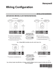
To connect the PC to a PLC; hook up an RS232 cable from the PC's
serial port (either COM1 or COM2) to the 9-pin male D connector on the
RS232 to RS485 converter.
Then plug the converter into the RS485 15pin female D connector on the HE200 PLC.
3
Alternatively, the PC can be connected to an HE200CGM200 RS232 to HE200
Network Gateway, by hooking an RS232 cable from the PC's serial port
to the 9-pin female D connector on the Gateway.
LADDER LOGIC FUNCTIONS
-
+----------------------*•* Functions---F1...F10-----------------------+
|HELP | N.O. | N.C. |Start |Close |Motor |Intern|Short | Open |Global|
| HELP |Switch|Switch|Branch|Branch|Output|Output|Input |Input |Output|
| HELP|-] [- |-]\[- | +- | -+ | -()- | -{}- | o--o |-o o-|-{g}- |
+---------------------------------------------------------------------+
+---+
| ^ |
+---+
| v |
+---+
+----------------------*•* Functions---F1...F10-----------------------+
|HELP |On
|Off
| Up |
|
|
|
|
|
|
| HELP |Timer |Timer |Count |
|
|
|
|
|
|
| HELP|[+TMR]|[-TMR]|[+CTR]|
|
|
|
|
|
|
+---------------------------------------------------------------------+
+---+
| ^ |
+---+
| v |
+---+
Normally Open Switch:
Ixx
-] [-
Identified I1 to I8, Q1 to Q8,
T1 to T48, S1 to S16, IG1 to
IG16 or QG1 to QG16.
Places a normally open switch.
-
Normally Closed Switch: Ixx
-]\[-
Identified I1 to I8, Q1 to Q8,
T1 to T48, S1 to S16, IG1 to
IG16 or QG1 to QG16.
Places a normally closed switch.
-
Start Branch:
-
Close Branch:
-
Physical Output:
-+
|
This function has no identifier.
+
Starts a vertical branch in the ladder logic.
+|
This function has no identifier.
+
Finishes the last branch started by connecting the lower
horizontal branch to the correct upper horizontal branch.
Qx
-()-
Identified Q1 thru Q8.
Some HE200 PLCs are specialized for motor control as follows:
When an odd output (Q1,Q3,Q5,Q7) is ON, the connected motor
runs; when OFF, the motor stops with dynamic braking.
The
even outputs (Q2,Q4,Q6,Q8) determine motor direction.
- Internal Output:
Txx
-{}Identified T1 thru T48.
These outputs can be turned ON or OFF by logic, and are
typically used to store intermediate or temporary logic
4
states.
LADDER LOGIC FUNCTIONS - (cont'd)
-
Short Circuit Switch:
Ixx
+-] [-+
|
|
+-----+
This function is not identified
specifically, but adds information to the selected function.
This operation forces the selected input object (I, Q, T, IG,
QG, S) to always be in an ON state, and is useful for debugging.
-
Open Circuit Switch:
Ixx
+-] [-+
|
|
+o
o+
This function is not identified
specifically, but adds information to the selected function.
This operation forces the selected input object (I, Q, T, IG,
QG, S) to always be in an OFF state, and is useful for debugging.
-
Global Input:
IGxx
-]g[-
Identified IG1 through IG16.
This function is entered and acts like a normally open or
closed switch, but receives its ON/OFF state from another PLC
node, via the HE200 Network. Each Global Input is assigned to
another PLC's Global Output.
These assignments are user-defined, in a table accessed by the
NET ASSIGNMENTS option under CONFIG in the MAIN MENU. When
selected, the NET ASSIGNMENTS command displays the following:
+--------------------Network Assignments--------------------+
|
|
|
<+> or <-> offset uses relative node addressing
|
|
|
|
Default Target PLC:
xxx
|
|
|
| INPUT
NODE
QG
INPUT
NODE
QG
|
| IG1:
yyy
zz
IG9:
xxx
zz
|
| IG2:
yyy
zz
IG10:
yyy
zz
|
|
.
.
|
|
.
.
|
| IG8:
yyy
zz
IG16:
yyy
zz
|
|
Press <ESC> to continue
|
+-----------------------------------------------------------+
Where:
xxx
Current ladder program's default Target
Network ID for downloading purposes
5
PLC
yyy
zz
The scanner uses node 64 as a default. The global
outputs can change, but 64 is the preferred node
default.
QG number from 1 to 16
LADDER LOGIC FUNCTIONS - (cont'd)
-
Global Input Example:
Entry in Node 20's Network Assignment Table:
|
|
INPUT
IG1:
NODE
10
QG
12
Rung in Node 20's Ladder logic:
10-12 SW_01
MOT_1
--]g[---] [----------------------------------------------( )IG01 I03
Q01
This rung of ladder code will turn Node 20's Motor #1 ON, if
Node 20's I3 is ON and Node 10's QG12 is ON.
-
Global Output:
QGxx
-{g}-
Identified QG01 through QG16.
This function behaves like an internal output, but is available to other HE200 PLCs on the HE200 Network.
-
-
ON Delay Timer:
S01+------+
---|enable|
|xxxx.x|
-|reset |
|ON dly|
+------+
Identified TMR1 through TMR16.
Two TMR/CNTs cannot share the
same identification number. This
function has Enable and Reset
inputs, a logical Output, and a
time Delay (Max 3200.9 seconds).
a.
If Reset is ON, the timer's Output is always OFF.
b.
If Reset is OFF, the timer's Output follows the timer's
Enable, with a programmable Delay in the OFF to ON edge.
OFF Delay Timer:
S02+------+
---|enable|
|xxxx.x|
-|reset |
|OFFdly|
+------+
Identified TMR1 through TMR16.
Two TMR/CNTs cannot share the
same identification number. This
function has Enable and Reset
inputs, a logical Output, and a
time Delay (Max 3200.9 seconds).
a.
If Reset is ON, the timer's Output is always ON.
b.
If
Reset is OFF,
the timer's Output
6
follows the timer's
Enable, with a programmable Delay in the ON to OFF edge.
LADDER LOGIC FUNCTIONS - (cont'd)
-
Up Counter:
S03+------+
---|clk
|
|xxxxx |
-|reset |
|UP CNT|
+------+
Identified CNT1 through CNT16.
Two TMR/CNTs cannot share the
same identification number. This
function has Clock and Reset
inputs, a logical Output, and a
Counts value (Max 32767 counts).
a.
If Reset is ON, the counter's Output is always OFF.
b.
If Reset is OFF, the counter increments each time Clock
goes from OFF to ON. When the Counts value is reached, the
counter's Output goes ON.
Note: The Sxx coil attached to timer or counter blocks
represents the internal state of the block and can be used as a
referenced as a normally open or closed contact for control.
STARTING THE HEPLC EDITOR
The HE200 PLC Ladder Editor is contained in the HEPLC.EXE DOS
executable file. The software is easy to learn, and can be operated by using just the keyboard, or by a combination of the keyboard and a Microsoft-compatible mouse.
HEPLC may be
prompt:
HEPLC
started by typing
the following at
the DOS command
Uses PC's COM1 port to communicate with PLCs,
auto-detects mouse, displays progress messages and
auto-verifies during downloads and beeps on error
HEPLC may also be started using one or more optional command line
switches, as follows:
HEPLC
HEPLC
HEPLC
HEPLC
HEPLC
2
Uses PC's COM2 port to communicate with the PLC.
k
Forces keyboard only mode.
f
Speeds downloading by not pausing for messages.
v
Turns off auto-verify after downloads
s
Turns off error sounds
HEPLC file.plc Loads the file 'file.plc' at startup
Switches must be in lower case and may be combined, for example:
HEPLC 2 k
Uses PC's COM2 port to communicate with
and forces keyboard only mode.
7
the PLC
NOTE:
When using a serial mouse, it must be on a different COM
port than the one used to communicate with PLCs. If the
mouse is connected to COM1, use "HEPLC 2". If the mouse
is connected to COM2, use "HEPLC". To totally disable the
mouse, use the "k" switch.
MENUS
There are 2 menus, the OBJECT MODIFICATION MENU and the MAIN MENU,
that are used for editing and debugging ladder programs.
When the Object Modification Menu is invoked, a purple arrow
appears.
The user should make sure this arrow is pointing to the
correct object, before proceeding with any modification.
The MAIN MENU can be invoked by pressing the <Alt> key or the
right mouse button, and the OBJECT MODIFICATION MENU can be
invoked by placing the cursor on the object to be modified and
pressing <Enter> or the left mouse button.
Both of these menus are described in detail below.
OBJECT MODIFICATION MENU
There are 4 commands in the
MODIFY, INSERT, and DELETE.
VIEW -
DISPLAYS
Object
Modification
Menu:
VIEW,
EXAMPLES
Type of Function
Name of Function
Number of Function
Node
QG
Status of Function
State of Function
I, Q, T, S, IG, QG
Lim_SW_1
1 to 48
1 to 253 (IG only)
1 to 16 (IG only)
Normal, Shorted, Opened
ON or OFF
If the PC gets disconnected from the HE200 PLC, then
the STATE of the function will turn to ???, and an
error will be displayed until the connection is
re-established.
MODIFY -
Display and modify properties of an existing object.
INSERT -
Insert an object to the left of selected object.
DELETE -
Delete a component, and automatically re-route all the
branches correctly.
MAIN MENU
There are 5 commands under the Main Menu: FILE, EDIT, MODE,
CONFIG, and TOOLS. Each of these commands brings up a sub-menu as
8
described on the following pages.
MAIN MENU - (cont'd)
FILE Sub-Menu
NEW
- Starts a new ladder program.
SAVE
- Saves complete or incomplete ladder program to the
current working directory.
LOAD
- Loads a previously saved complete or incomplete
ladder program from the current working directory.
LOAD
NAMES
- Loads just the user I/O Names from a saved ladder
program file. This allows adding names to an
uploaded program or allows a standard set of names
to be "copied" from a saved program.
DOWNLOAD
- Downloads PC's current ladder program to the Target PLC unless one or more rungs are incomplete.
The PLC is put in IDLE mode while downloading, and
is returned to the previous mode after a successful download. If the download is not successful,
the PLC is left in IDLE mode.
UPLOAD
- Uploads ladder program from the Target PLC to the
PC for editing or monitoring.
Uploaded programs
contain all information except the user I/O Names.
The I/O names can be loaded separately from a
saved file, via the LOAD NAMES option.
VERIFY
- Compares PC's current ladder program to the Target
PLC's ladder rogram.
If a verify error is
detected, one of three error messages will be
displayed:
"Verify Failed in Network Info Block" and the PC differ in network assignments.
The PLC
"Verify Failed in Timer Info Block" - The PLC and
the PC differ in timer settings.
"Verify Failed in Code Block" - The PLC and the PC
differ in ladder logic.
PRINT
- Prints selected portions of the currently loaded
ladder program to the printer connected to the
lpt port defined by the PRINTER PORT field. Print
options include the range of ladder rungs to
print, network assignments, I/O names and timer
information.
In addition, either ASCII text or ASCII graphics
printing mode may be selected.
ASCII graphics
mode uses IBM line-drawing graphics characters,
supported by many printers, to produce a higher
9
quality printout.
MAIN MENU - (cont'd)
FILE Sub-Menu - (cont'd)
PRINT
(cont'd)
- Also, if the editor's Display Filter tool is
active when print is selected, the printout will
only contain the viewable, filtered rungs.
The
top of these printouts will label it as a filtered
ladder program, and will show the output used to
filter the ladder code.
See the Display Filter
option under the TOOLS Sub-Menu for more details.
RUN
SCRIPT
- This feature allows automated ladder program downloading to an entire network of PLCs.
To use this feature, an ASCII script file, named
PLC_LIST.TXT, must be created using an ASCII text
editor such as MS-DOS EDIT (type EDIT PLC_LIST.TXT
at the DOS prompt).
The PLC_LIST.TXT file should contain one line of
ASCII text for each download to be performed.
Each line starts with a PLC Network ID (1 to 253),
followed by spaces or tabs, and then the name of
the file (up to 8 characters with no extension;
.PLC is assumed) containing the ladder program to
be downloaded to the specified PLC, and finally a
carriage return.
The following
format:
1
2
3
47
34
32
is
an
example
of
the
required
MERGE
DIVERT
FILE_3
FILE_47
MERGE
FILE_32
After the PLC_LIST.TXT file has been created, a
script download can be started, by selecting RUN
SCRIPT from the FILE menu.
When script processing is complete, an ASCII text
file named PLC_LIST.LOG is created or appended,
which contains the results of the script download.
This file can be viewed with a text editor or by
typing TYPE PLC_LIST.LOG | MORE at the DOS prompt.
If a file could not be loaded or downloaded, an
error message will be placed in the log file.
When a file is successfully loaded and downloaded,
the time and date of the download will be listed
in the log file.
QUIT
- Return to DOS.
10
MAIN MENU - (cont'd)
EDIT Sub-Menu
UNDO
- Undo last inserted/deleted object.
DELETE RUNG - Deletes the current rung and moves ladder rungs
(CTRL-X)
up one rung. Deleted rung is stored in a buffer
for later pasting into other places.
INSERT RUNG - Inserts a blank rung before the current rung, if
(CTRL-I)
ladder program is not full.
Moves current and
later rungs down one rung.
PASTE RUNG
(CTRL-V)
- Places a previously deleted or copied rung from
the paste buffer onto an unused rung.
A rung
may be pasted multiple times.
COPY RUNG
(CTRL-C)
- Copies the current rung into the paste buffer
without modifying the current rung.
FIND
(CTRL-F)
- Finds the first occurrence in the
gram, of a user selectable object.
ladder pro-
After selecting FIND, enter the TYPE and NUMBER
of the object to search for.
To search for
timers, enter "S" for TYPE followed by the timer
NUMBER and limit to "OUTPUTS ONLY".
By default, FIND will search for objects used as
either inputs or outputs. Pressing <SPACE> will
limit the search to outputs only.
Pressing
<SPACE> again will toggle back to inputs or
outputs.
If an object can't be found, an error
message is displayed.
FIND NEXT
(CTRL-N)
- Finds the next occurrence of the object
viously selected via the FIND option.
pre-
MODE Sub-Menu
IDLE
- Ladder logic stops running. Temporarily enters
this mode when downloading ladder logic programs
from the PC to the PLC.
Outputs Q1 through Q8
may be "forced" ON or OFF in this mode.
MONITOR
- Ladder logic runs with power flow and timer
monitoring enabled.
Red = object in the OFF
state and Green = object in the ON state. When
in the Monitor mode, the pull down menu for MODE
contains a check next to Monitor.
RUN
- Ladder logic runs
disabled.
11
with
power
flow
monitoring
MAIN MENU - (cont'd)
CONFIG Sub-Menu
PC PORT
- Choose the PC serial port (COM1 or COM2) or PC
internal gateway (HE200CGM302) channel for communication with PLCs. This choice overrides any
command line option concerning the PC port.
PLC INFO
- Displays the Target PLC's Model Name, Ladder
Execution Engine Firmware Revision, Mode, PLC
Scan Rate, I/O Conditioning Settings, Ladder
Memory Used, and Self Test Result.
I/O NAMES
- Displays UNUSED I/O as Gray. Displays USED I/O
as Yellow if ON, or Red if OFF. If Target PLC
becomes disconnected,
the
display
remains
unchanged, except that an error is displayed
until the connection is re-established.
Internal coils (T1 - T48) will be denoted with
an upper case "T" if the coil is used as an
output, and a lower case "t" if it is only used
as an input, or as a timer reset.
<PAGE DOWN> shows the usage, state, count and
set point of all counters and timers. <PAGE UP>
returns to the original I/O Names screen.
NET
- Used to view/change PLC node and QG assigned to
ASSIGNMENTS
each Global Input.
Also used to view/change
Target PLC assigned to current ladder program.
TOOLS Sub-Menu
SET LOCAL PLC
- Views/changes Local PLC's Network ID.
The
Local PLC is the one whose RS232 or RS485
programming port is connected to the PC's COM
port.
Note that some HE200 PLC models have
rotary switches which set their Network IDs
and therefore don't support the SET LOCAL PLC
option.
SET TARGET PLC - Views/changes Network ID of Target PLC. The
Target PLC is the one which may be communicated with by HEPLC, for ladder program
downloading, monitoring and executing.
The
Target PLC may be the Local PLC, or another
PLC accessed via the HE200 Network through
the Local PLC or through an HE200 Network
gateway.
12
MAIN MENU - (cont'd)
TOOLS Sub-Menu - (cont'd)
SEARCH NETWORK - Scans HE200 Network and displays current
state of all connected PLC nodes. Scanning a
network with few connected nodes may take as
long as two minutes.
Pressing the ESC key
will halt the scanning.
Pressing the S key
after a scan will rescan all nodes. The display shows nodes 1 to 253 with a status to
the right as follows:
xxx
Represents a node number from 1 to 253
xxx-?
Node xxx doesn't exist or is not communicating.
xxx-I
Node xxx is in IDLE
municating.
xxx-M
Node xxx is in
communicating.
xxx-R
Node xxx is in RUN mode and is communicating.
xxx-E
Node xxx failed its power-on-self-test.
mode and is com-
MONITOR
mode
and
is
FORCE OUTPUTS
- Use this to manually
outputs (Q1 to Q8) ON
only).
force Target PLC's
or OFF (IDLE MODE
I/O
CONDITIONING
- HE200 PLC engine firmware version 1.90 and
later, supports two adjustable parameters to
help when the PLC is used in an environment
with excessive electrical noise.
The first setting, "Input filtering", sets
the number of PLC scans a physical input (I1
to I8) must remain stable before a state
change is accepted.
A setting of 0 turns
this feature off, which is the default.
The second setting, "Max.
network update",
sets the maximum time a PLC will wait before sending its global data (QG1 to QG16),
and is in multiples of 100 mS. A setting of
0 turns this feature off, which is the
default.
MAIN MENU - (cont'd)
TOOLS Sub-Menu - (cont'd)
13
DISPLAY FILTER - Powerful debugging option which allows a programmer to view or print only those rungs
that can affect a chosen output.
For
example, if Q1 is not behaving as
expected, the programmer could enter Q1 as
the output to use to filter the display. Now
when viewing or printing the rungs only rungs
that could possibly change the output Q1 are
displayed.
After selecting DISPLAY FILTER option from
the TOOLS menu, enter the TYPE and NUMBER of
the output object to filter the display for.
Now the word "Filtered", and the output
object the filter is based upon, will appear
at the top of the ladder program window.
Filtering is removed by
FILTER option again and
option.
Starting a new
new program will also
filtering.
choosing the DISPLAY
selecting the cancel
program or loading a
remove the display
When filtering is performed, the ladder program is checked to make sure that all T, Q
and QG objects, which appear as input contacts, also appear as output coils. If this
is not the case, a warning screen will list
the objects and rung numbers where this occurs.
An example of this is when T1 is used
as an input somewhere in the ladder code, but
is never used as an output. In this case, T1
will always be OFF and therefore cannot cause
the rung's output to toggle.
DIAGNOSTICS
- This function will display
power-on-self-test results.
the Target PLC's
EDIT DESCRIPTION
- Allows saving, viewing and printing a simple
description for the current program.
RUNG COMMENT
- Assigns
a
descriptive
comment
to the
current rung. The comment will appear in
the lower right side of the editing window,
and will appear below the rung when printing.
Comments can be added or modified by left clicking the comment on the lower right side
of the edit window.
ABOUT
- Displays software version number and other
status information regarding the HE200 PLC
Ladder Editor Programming Software (HEPLC).
EDITING AND CREATING LADDER LOGIC PROGRAMS
14
USING THE KEYBOARD:
ESC
- Goes back 1 level from any menu. If pressed repeatedly, offers the option to exit to DOS.
ALT
- Brings up the MAIN MENU only
menus present on the screen.
CTRL-H
- Toggles node ID display and entry format (HEX/DEC)
Home
- Scrolls up the available ladder object functions.
End
- Scrolls down the available ladder object functions.
U
- Scrolls up the branches within a rung.
D
- Scrolls down the branches within a rung.
PgUp
- Scrolls up one rung.
PgDn
- Scrolls down one rung.
when there are no other
Ctrl-PgUp - Scrolls up ten rungs, if possible.
Ctrl-PgDn - Scrolls down ten rungs, if possible.
Cursors
- Arrow keys move around on the screen when editing ladder programs, if HEPLC is started with the "k" option.
F1..F10
- F1 for online help; F2-F10 to select desired function
to be placed in the ladder program.
TAB
- Move from one field to another
require user input.
Enter
- Fill in identification fields to be placed in the
ladder program.
Place function selected by function
keys into the ladder program.
Ctrl + c
- Copy current rung to paste buffer
Ctrl + d
- Download the current ladder program
Ctrl + f
- Find object in ladder program
Ctrl + h
- Toggle HEX / DEC node display
Ctrl + i
- Insert a blank rung
Ctrl + l
- Load a new ladder program
Ctrl + n
- Find next object after current rung
Ctrl + p
- Print the current ladder program
Ctrl + r
- Rung Comment edit and view
15
in dialog boxes which
Ctrl + s
- Save the current ladder program
Ctrl + v
- Paste rung onto current empty rung
Ctrl + x
- Cuts current rung to paste buffer
USING THE MOUSE:
RIGHT BUTTON -
Used to bring up the Main Menu only when there are
no other menus present on the screen.
LEFT BUTTON
-
Used for scrolling by
arrows on the screen.
Home, and End keys.
LEFT BUTTON
-
Used to select desired function by clicking on it.
Replaces F1 through F10 keys.
LEFT BUTTON
-
Replaces the
<Enter>
IDENTIFICATION FIELDS.
clicking the appropriate
Replaces U, D, PgUp, PgDn,
key,
except
in
the
IDENTIFICATION FIELDS
When a function is placed in the ladder logic program, a dialog
box pops up, which allows the user to fill in the identification
fields.
These fields are used by the PC and the PLCs to identify
each function.
The user must fill in all the fields except the Name field which
is optional in all cases. If a Name is entered or changed at any
time, the software updates that Name everywhere that function is
present in the entire ladder program when the screen is updated.
To correct any of the fields, TAB over to the appropriate field
and enter the new values.
The following are field descriptions
for some functions:
INPUTS
+-----------------INPUT-----------------+
|
Normally: Open
|
Possible types are:
|
|
Physical Input (I) |
Type: i
I, Q, T, S, IG, or QG
|
Physical Output (Q) |
|
Internal Output (T) |
Number: 3
Name: Switch_3
|
Timer State
(S) |
|
Global Input
(IG) |
OK
CANCEL
|
Global Output
(QG) +------<SPACE> Toggles OPEN/CLOSED------+
User enters Type, Number
and optionally Name.
OUTPUTS
+----------------OUTPUT-----------------+
|
|
16
Possible types are:
Physical Output (Q)
Internal Output (T)
Global Output
(QG)
User enters Number and
optionally Name.
|
|
|
Number: Q1
Name: Motor_CW
|
|
|
|
|
|
|
|
OK
CANCEL
|
+---------------------------------------+
TIMERS
+-----------------TIMER-----------------+
|
Number: 3 Resolution: 100ms
|
Possible types are:
|
|
ON Delay
(+TMR) |
Reset: I 4
Delay before: ON
|
OFF Delay
(-TMR) |
|
|
Time: 12.4
seconds |
User enters timer Number,|
|
Reset condition and Time |
OK
CANCEL
|
in seconds. Up to 2 de- +---------------------------------------+
cimal places may be entered for Time value. 0 or 1 decimal places
selects 100mS timer resolution with a maximum delay of 3200.9 seconds. Typing 2 decimal places selects 10mS resolution with a maximum delay of 320.99 seconds.
IDENTIFICATION FIELDS - (cont'd)
COUNTERS
+----------------COUNTER----------------+
|
Number: 3
UP Counter
|
Possible types are:
|
|
UP Counter
(CNT) |
Reset: I 4
Delay before: ON
|
|
|
User enters counter Num- |
Counts: 12
|
ber, Reset condition and |
|
Counts value. Max Counts|
OK
CANCEL
|
value is 32767.
+---------------------------------------+
ERROR MESSAGES, LIMITS AND RESTRICTIONS
ERROR WINDOW:
Every time an error occurs, whether it is a user
error or a system error, an error message will be
displayed in RED for 5 seconds in the top middle
of the screen, and a BEEP is generated (unless
disabled via the "s" command line switch) by the
PC speaker. The user should pay close attention
to this window.
BRANCH LIMIT:
Vertical branches may
deep per rung.
RUNG LIMIT:
There is a rung limit of 128 rungs.
Note that
only 72 rungs are possible without using an output
more than once.
RUNG OUTPUT:
There must be one and only one output per rung.
TIMERS /
You may not OR around a timer or counter.
17
be placed
up to
8 levels
A timer
COUNTERS
or counter may not be the leftmost object on a
rung.
The maximum number of timer and/or counter
objects is 16. Each timer and/or counter MUST be
assigned a unique number from 1 to 16.
BRANCHES:
All branches must
output.
BRANCHING:
To open a branch, press F4 to select start branch,
then place the cursor at point you want the branch
to be opened, then press enter or click the left
mouse button.
Similarly, to close a branch,
choose close branch by pressing F5, place the
cursor at the branch that is to be closed, and
press <Enter> or click the left mouse button. To
delete a branch, bring up the Object Modification
Menu,
making sure that the purple arrow is
pointing to the branch in question, and then
choose DELETE.
MOUSE:
To disable the mouse entirely and use the keyboard
by itself, invoke the program using "HEPLC k".
CURSOR KEYS:
If the software does not detect a mouse, it allows
use of the arrow keys to move the cursor.
be
closed
before
placing
an
TUTORIAL
This tutorial shows how to create the simple ladder program shown
below, using the just the keyboard. The program should be invoked
using "HEPLC k" to disable the mouse.
|STOP
START SEN_1
MOTOR |
+-]\[-+-] [-++-] [-+-------------------------------------( )-+
|I01 |I02 ||I03 |
Q01
|
|
|
||
|
|
|
|MOTOR||LSW_1|
|
|
+-] [-++-] [-+
|
|
Q01
I04
|
The following are descriptions of some of the keys used:
<tab>
<F?>
<up>
<right>
<down>
<cr>
=
=
=
=
=
=
TAB key
Function key (F2...F10)
Up arrow cursor key
Right arrow cursor key
Down arrow cursor key
Enter key
NOTE:
Mouse users may click the left mouse button at appropriate screen locations, to emulate the TAB, F2...F10,
and arrow keys.
CREATING THE LADDER PROGRAM
18
1.
STOP Switch Input:
<F3> <cr> I <tab> 1 <tab> STOP <tab> <cr>
2.
START BRANCH:
<right> <right> <right> <F4> <cr>
3.
START Switch Input:
<right> <F2> <cr> I <tab> 2 <tab> START <tab> <cr>
4.
MOTOR Contact:
<down> <down> <down> <F2> <cr> Q <tab> 1 <tab> MOTOR <tab> <cr>
5.
CLOSE BRANCH:
<right> <right> <F5> <cr>
6.
START BRANCH:
<up> <up> <up> <right> <right> <F4> <cr>
7.
SENSOR 1 Switch Input:
<F2> <cr> I <tab> 3 <tab> SEN_1 <tab> <cr>
CREATING THE LADDER PROGRAM - (cont-d)
8.
LIMIT SWITCH 1 Switch Input:
<down> <down> <down> <F2> <cr> I <tab> 4 <tab> LSW_1 <tab> <cr>
9.
CLOSE BRANCH:
<right> <right> F5 <cr>
10. MOTOR Output:
<up> <up> <up> <right> <right> <F6> <cr> 1 <tab> MOTOR <tab> <cr>
After creating a ladder program, it may be inspected by placing
the cursor on each function individually, and then pressing Enter
or the left mouse button to bring up the Object Modification Menu
and choosing VIEW. Alternatively, select I/O NAMES under CONFIG
in the MAIN MENU, which can be brought up by pressing the ALT key
or the right mouse button.
SAVING THE LADDER PROGRAM
The program can be saved by choosing SAVE under FILE in the MAIN
MENU, and similarly the program can be reloaded by choosing LOAD.
EDITING THE LADDER PROGRAM
After a rung is complete, ladder
viewed, modified, inserted, or
Modification Menu.
19
objects within the
deleted by using
rung may be
the Object
If a ladder object is inserted or deleted by mistake, select the
UNDO command under EDIT in the MAIN MENU.
Finally, the other EDIT commands allow deleting, inserting, pasting, and copying of complete rungs.
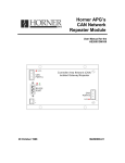
APPENDIX A - The HE200 Network
BACKGROUND ON THE HE200 NETWORK
The HE200 Network is based on CAN (Controller Area Network), which
is widely used for automotive and more recently industrial control
applications.
Data is passed at 125,000 bits per second using a
differential pair of wires, plus a ground. The CAN implementation
in HE200 PLC controllers, allows up to 64 controllers to be networked with no additional hardware, and up to 253 with three CAN
repeaters (HE200CGM100).
For the ladder programmer, little knowledge of the networking
procedures is needed, however for trouble shooting and optimizing,
the following information can be helpful.
Because the network
does not use master/slave or token passing, the hardware selfarbitrates based on Network ID.
PLCs with lower Network ID
numbers are given higher priority.
When a PLC needs to send data over the network it first waits for
the network to be idle (currently a maximum of 400 uS). If two
PLCs start "talking" at the same time, the "self-arbitration"
causes the PLC with the greater Network ID number to stop, without
affecting the other PLC's started message.
In applications with a large number of networked PLCs, better
results may be achieved by assigning lower Network IDs to PLCs
that have more critical network data than other PLCs. Similarly,
by assigning higher Network IDs to PLCs that are expected to
produce many network updates, these PLCs are prevented from monopolizing the bus time.
Each PLC has 16 global output bits (QGs), which are periodically
broadcast to the other PLCs on the network. QG1 to QG16 may be
used in ladder logic like any coil.
All
of
its
may
ly,
can
16 global outputs are broadcast to the network each time one
them changes state. In addition, if a PLC has not transmitted
global data for a while, the PLC's programmable network timer
expire, which in turn causes a global data broadcast. Finalas part of its power-up initialization sequence, another PLC
explicitly request a PLC to broadcast its global data.
In addition to global data, the HE200 Network is used to exchange
data between a PLC on the network and a PC-based Host Supervisory
Tool, such as the HEPLC Ladder Editor, or an OEM-specific cell
controller.
Refer to the "HE200 Network Protocol" document for details on the
CAN Message Encoding and Host Supervisory Tool Protocol used to
accomplish HE200 Network communication.
20
PHYSICAL CONNECTIONS
Wire type, gauge and terminators should comply with current specifications for CAN inter-connections, based on length and required
noise immunity.
The HE200 PLC connector, has four
beled 1 through 4 as follows:
Terminal
Description
screw terminal connections la-
1
Ground return for terminals 2 and 3
2
CAN DATA +
3
CAN DATA 4
Cable shield
The following diagram shows how to properly wire multiple nodes
together on an HE200 Network:
SCANNER
PLC
V-
Shield
120 Ω
Earth Ground
CAN _ High
CAN_ Low
V+
WIRING RULES
1.
An HE200 Network should be wired in a
fashion, such
that there are
exactly
endpoints on the network.
2.
The two nodes at the physical endpoints, should have 120Ω
terminating resistors connected across terminals 2 and 3.
3.
The data conductors (terminals 2 and 3) should be a 24 AWG
shielded twisted pair, with 120Ω characteristic impedance.
4.
Notice that for a section of cable between two nodes, the
cable shield is connected to terminal 4 at one end only.
5.
An HE200 Network (without repeaters) should be limited to
64 nodes with a maximum cable length of 1500 ft.
6.
Up to four HE200 Network segments, which adhere to the
above five rules, may be connected together using three
CAN repeaters (HE200CGM100).
In this manner, a CAN
network may be extended to 253 nodes with a total cable
distance of 6000 ft.
7.
Each HE200 PLC unit is assigned a unique Network ID by the
HEPLC programming software via the RS485 port.
21
daisy-chained
two physical
APPENDIX B - HE200 PLC BIOS Firmware Ver 1.53
INTRODUCTION
This document describes the (normally
programmed into EPROM in HE200 PLCs.
invisible)
BIOS
firmware
Normally, when the controller powers up, the BIOS firmware just
starts the HE200 PLC ladder execution engine, which in turn
executes ladder code if the engine is not in IDLE mode.
When activated, the BIOS firmware displays a menu which can be
used to perform basic tests of the controller board's hardware,
and can load the latest PLC ladder execution engine into nonvolatile memory on the controller board.
The operator interface to the BIOS menu, consists of a PC/AT
running a dumb terminal program (TERM.EXE) while connected to the
controller board's main serial port via an RS232 to RS485 adapter.
ACTIVATING THE BIOS MENU
Before using the BIOS menu as
activated as follows:
described above, it
must first be
1.
Connect a PC/AT to board's main
to RS485 adapter (HE693SNP232).
serial port via an RS232
2.
Run the TERM.EXE program set for 9600 Baud, no parity, 1
stop bit, XON / XOFF handshaking and ANSI display mode.
3.
While holding down the PC's spacebar, power up the HE200
PLC. BIOS Ver 1.53 and above is compatible with the standard IBM keyboard repeat rate (10 cps) or faster.
4.
The following menu should now be displayed on the PC:
-------------------------------| HE200xxxxxx BIOS Menu V 1.53 |
-------------------------------P
W
L
V
E
=
=
=
=
=
Show menu on PC.
Show menu on WY-30.
Load new software.
Verify software.
Erase Flash EPROM.
22
R
S
M
T
X
=
=
=
=
=
Receive messages.
Send message.
Multiple transmit.
Test I/O points.
Exit BIOS menu.
USING THE BIOS MENU
As the menu shows, the BIOS supports 10 commands which may be selected by the operator.
The BIOS commands fall into the following three categories:
CATEGORY
COMMANDS
Utility
P, W
Hardware Testing
R, S, M, T
PLC Engine Maintenance
L, V, E, X
UTILITY COMMANDS
P or W is pressed on the keyboard to "repaint" the BIOS menu using
ANSI PC or WYSE WY-30 screen control codes respectively.
Note that if a WYSE terminal is used
items except L and V are available.
instead of a
PC, all menu
HARDWARE TESTING
In addition to hardware testing, the R, S and M command may be
used as HE200 Network debug tools during ladder program development.
The R command displays network messages received from other PLCs
until ESC is pressed. If the optional node address is entered,
only messages sent by that node will be received. To receive all
messages, just press enter when prompted for node address.
Received messages are displayed in the following format:
Node address: nnn
Message type: t
Data: lo hi
Where nnn is the sender's node address (0 to 253 decimal), and t
is message type (S, R, H or N). For type S messages, lo is the
low global data byte (QG1 to QG8), and hi is the high global data
byte (QG9 to QG16). Global data is displayed in hexadecimal.
The S command sends a network message to other PLCs. The user is
prompted for the node address, message type (S or R), low global
data byte (QG1 to QG8) and high global data byte (QG9 to QG16).
The M command continuously sends the last message sent via the S
command, until the user presses ESC. The user is prompted for an
inter-message delay value from 0 to 9999, in units of 750 nS.
The T command continuously copies all 8 physical inputs to all 8
physical outputs until the user presses ESC.
PLC ENGINE MAINTENANCE
23
When a new version of the PLC execution engine becomes available,
it may be downloaded into the controller board's non-volatile
memory chip via the L menu selection, along with the F2 download
function of the TERM.EXE program.
When the L
displayed:
command is
selected, the
following message
will be
Loading new software ...
At this point, press the F2 function key, and enter the proper
filename to start the download. The filename to enter depends on
the model number of the PLC being updated, and the new engine's
version number as follows:
PLC Model
Filename
HE200PLC044
HE200PLC084
HE200PLC088
HE200PLC188
HE200UCN014
HE200UCN114
PLC088.ver
PLC084.ver
PLC088.ver
PLC188.ver
UCNX14.ver
UCNX14.ver
[Note that ver is the 3 digit
version number of the engine
being installed.]
During download, an automatic verify is performed and, if all goes
well, the display should read:
Loading new software ... Done.
The V command is used in the exact same manner as L, except that
instead of downloading a new execution engine, it simply compares
the specified file with the engine currently residing in the controller's non-volatile memory.
The E command erases the entire non-volatile memory chip. This
command will be rarely used.
Normally, it should NOT be necessary to run the E command prior to running the L command.
The X command causes a hardware reset to be performed, which in
turn starts up the PLC execution engine, if one has been
previously loaded into non-volatile memory (via the L command).
IMPORTANT NOTE: Some PLC models, such as the HE200PLC188 and the
HE200UCNx14, have software-controlled non-volatile
memory write-protection.
For these models, the
UNLOCK.HEX file must be downloaded to the PLC (via
the L command), before a new engine can be downloaded.
APPENDIX C - HE200 PLC BIOS Firmware Ver 3.00
INTRODUCTION
This document describes the (normally invisible) BIOS firmware
programmed into EPROM in HE200 PLCs and HE200CGM301/302 Gateways.
24
HE200 BIOS Firmware Version 3.00 represents a major update, in
that it allows HE200 PLC and HE200CGM301/302 Gateway engine maintenance via the HE200 (CAN) Network, instead of requiring direct
connection.
This engine maintenance is performed using the HE200 BIOS Access
Utility (HEBIOS.EXE) which assumes that all devices on the network
(PLCs and Gateways) contain BIOS EPROMS Version 3.00 or later. It
is also assumed that all devices either have empty (erased)
non-volatile memory (Flash EPROMS) or are running engine software
Version 3.00 or later.
Normally, when an HE200 PLC powers up, the BIOS firmware just
starts the HE200 PLC ladder execution engine, which in turn
executes ladder code if the engine is not in IDLE mode.
When an HE200CGM301/302 Gateway powers up, its BIOS
normally just starts the HE200 Gateway execution engine.
firmware
When "activated" however, the BIOS firmware displays a menu, which
can be used to perform basic tests of the PLC or Gateway's
hardware, and which can load the latest execution engine into nonvolatile memory.
The operator interface to the BIOS menu, consists
running the HE200 BIOS Access Utility (HEBIOS.EXE).
of
a
PC/AT
ACTIVATING THE BIOS MENU
Before using the BIOS menu as
activated as follows:
1.
2.
described below, it
must first be
Physically attach the PC/AT to an HE200 Network in one of
the following ways:
a.
Connect the PC's COM1 or COM2 RS232 port to an HE200
PLC's programming port.
This allows HEBIOS.EXE to
access the PLC's BIOS menu, or the BIOS menu of any
node attached to the PLC's CAN port.
If the PLC's
programming port is a 15-pin RS485 connector, use an
RS232 to RS485 adapter (HE693SNP232).
b.
Connect the PC's COM1 or COM2 RS232 port to an HE200
Network Serial Gateway (HE200CGM200).
This allows
HEBIOS.EXE to access the BIOS menu of any node attached to the Serial Gateway's CAN port B.
c.
Install an HE200CGM301 (single) or HE200CGM302 (dual)
HE200 Network Gateway Interface Board into the PC's
ISA bus.
This allows HEBIOS.EXE to access the Gateway's BIOS menu, or the BIOS menu of any node attached
to the Gateway's CAN port A or B. Note that port B is
not available on the HE200CGM301.
Run the HEBIOS.EXE program by typing the following at the
DOS prompt:
HEBIOS [port]
25
where port is an optional parameter indicating what type
of connection was used to attach the PC to the HE200 Network.
A port value of 1 or 2 assumes that the PC's COM1 or COM2
port is attached.
If an HE200CGM301 or HE200CGM302 is being used, the port
value should be the Gateway's dual-port RAM segment address, as determined by its DIP switch setting (factory
default port values are D000 for CAN port A and D040 for
CAN port B).
If the port parameter is omitted, HEBIOS.EXE assumes COM1.
3.
Press F3 and type in the Target Node address (in decimal)
of the PLC or Gateway whose BIOS you want to activate.
4.
Press F1 to start the Target Node's BIOS menu.
5.
The BIOS menu should now be displayed on the PC.
THE BIOS MENU
When a PLC or Gateway's BIOS menu
displayed:
is activated, the following is
-------------------------------| HE200xxxxxx BIOS Menu V 3.00 |
-------------------------------P
W
L
V
E
=
=
=
=
=
Show menu on PC.
Show menu on WY-30.
Load new software.
Verify software.
Erase Flash EPROM.
Node Address:
R
S
M
T
X
=
=
=
=
=
Receive messages.
Send message.
Multiple transmit.
Test I/O points.
Exit BIOS menu.
hh Hex
ddd Dec
Note that the displayed Node Address should match the value previously entered via the F3 function key.
USING THE BIOS MENU
As the menu shows, the BIOS supports 10 commands which may be selected by the operator.
The BIOS commands fall into the following three categories:
CATEGORY
COMMANDS
Utility
P, W
Hardware Testing
R, S, M, T
PLC Engine Maintenance
L, V, E, X
26
UTILITY COMMANDS
P or W is pressed on the keyboard to "repaint" the BIOS menu using
ANSI PC or WYSE WY-30 screen control codes respectively.
Note that if a WYSE terminal is used
items except L and V are available.
instead of a
PC, all menu
HARDWARE TESTING
In addition to hardware testing, the R, S and M command may be
used as HE200 Network debug tools during ladder program development. Also, the R, S and M commands may not be used remotely. In
other words, they are available only when a HE200CGM302/301's BIOS
menu or a direct-connected PLC's BIOS menu is active.
HARDWARE TESTING - (cont'd)
The R command displays network messages received from other PLCs
until ESC is pressed. If the optional node address is entered,
only messages sent by that node will be received. To receive all
messages, just press enter when prompted for node address.
Received messages are displayed in the following format:
Node address: nnn
Message type: t
Data: lo hi
Where nnn is the sender's node address (0 to 253 decimal), and t
is message type (S, R, H or N). For type S messages, lo is the
low global data byte (QG1 to QG8), and hi is the high global data
byte (QG9 to QG16). Global data is displayed in hexadecimal.
The S command sends a network message to other PLCs. The user is
prompted for the node address, message type (S or R), low global
data byte (QG1 to QG8) and high global data byte (QG9 to QG16).
The M command continuously sends the last message sent via the S
command, until the user presses ESC. The user is prompted for an
inter-message delay value from 0 to 9999, in units of 750 nS.
The T command continuously copies all 8 physical inputs to all 8
physical outputs until the user presses ESC. Note that this command is only available on PLC BIOS menus, as HE200CGM301/302 Gateways have no physical I/O to test.
PLC ENGINE MAINTENANCE
When a new version of the PLC or Gateway execution engine becomes
available, it may be downloaded into the PLC or Gateway's
non-volatile memory chip via the L menu selection, along with the
F2 download function of the HEBIOS.EXE program.
When
the L
command is
selected, the
27
following message
will be
displayed:
Loading new software ...
At this point, press the F2 function key,
filename to start the download.
and enter
the proper
PLC ENGINE MAINTENANCE - (cont'd)
The filename to enter depends
Gateway being updated, and the
follows:
Model
Filename
HE200CGM301
HE200CGM302
HE200PLC044
HE200PLC084
HE200PLC088
HE200PLC188
HE200PLC288
HE200UCN014
HE200UCN114
CGM302.ver
CGM302.ver
PLC088.ver
PLC084.ver
PLC088.ver
PLC188.ver
PLC188.ver
UCNX14.ver
UCNX14.ver
on the model number of the PLC or
new engine's version number as
[Note that ver is the 3 digit
version number of the engine
being installed.]
During download, an automatic verify is performed and, if all goes
well, the display should read:
Loading new software ... Done.
The V command is used in the exact same manner as L, except that
instead of downloading a new execution engine, it simply compares
the specified file with the engine currently residing in the controller's non-volatile memory.
The E command erases the entire non-volatile memory chip. This
command will be rarely used.
Normally, it should NOT be necessary to run the E command prior to running the L command.
The X command exits the BIOS menu and starts up the PLC or Gateway
execution
engine (if one has
been previously loaded into
non-volatile memory via the L command).
IMPORTANT NOTES
Since HEBIOS.EXE was designed specifically for HE200 PLCs and
Gateways, it is no longer necessary to download the UNLOCK.HEX
file before engine updating. This function is now handled
automatically.
Because of the communications overhead required for engine downloading, the L and V commands may fail when attempting to update
an engine via the CAN network, if the network has other traffic on
it.
For this reason, the F5 function key may be used to put all
PLCs in IDLE mode. Then, when engine maintenance is complete, use
the F5 function key again to put all PLCs in MONITOR or RUN mode.
28
While a BIOS menu is active, the F3, F5 and F10 function keys are
disabled.
You must exit the active BIOS menu by typing X, before
setting a new Target Node, globally controlling PLCs, or quitting.
WHAT'S NEW IN HEPLC VERSION 1.8?
·
Network - Added TOOLS menu item to "attach" to Target PLCs via the
HE200 Network. Added TOOLS menu item to change Local PLC's
Network ID.
Added status display for Local PLC, Target PLC, and
Target PLC's state on main screen.
Can now download and monitor
remote PLCs via the HE200 Network.
·
Power Monitoring - when in the Monitor mode the PC constantly requests and displays the status of objects on the currently displayed rung. Red = object in the OFF state and Green = object in
the ON state. When in Monitor mode, the pull down menu for MODE
contains a check next to Monitor.
·
Downloading - Changed order and display so PC automatically
attaches to Target PLC before download.
·
File loading - PC attempts to automatically attach to the files
Target PLC during file loading.
·
Filename - The currently loaded file's name now appears along side
the current rung number on the editing screen. This filename is
the default when loading and saving files. When printing files in
the LoQ or HiQ format the filename now appears with the page, time
and date stamp. If no filename is assigned to the current
program, the editing screen displays the filename as UNNAMED. The
printout of a UNNAMED file will contain the time, date, and page
stamp, but no filename.
·
Delete - completed. New coding prevents corruption for all cases.
Allows deleting of first and last object, with error checking for
timers and outputs, that require a specific context.
·
Modify - completed. Allows user to modify the properties defined
for the object. Upon selecting modify, a set of data fields is
displayed, with the known fields filled.
·
Editing fields - redesigned so a valid character starts the
replacement of the current field with the entered characters.
·
Menu operations - the main menu and any of the sub menus may be
closed by clicking the left mouse button on any portion of the
screen that does not contain an active menu item. Along with this
change some minor menu handling bugs were fixed that caused first
menu items to be selected when the mouse was clicked in an
inactive menu area.
·
Function scrolling - when selecting Page-Up or Page-Down for
selecting the function set, the functions wrap around.
·
Communications timing - improved timing for many communications
functions to reduce errors and increase speed.
29
WHAT'S NEW IN HEPLC VERSION 1.9?
·
MODIFY - When modifying a non-global input object, the object can
now be changed between normally open and normally closed. This is
done by pressing the <F1> key any time a field is not being edited
(cursor is small "_" not big "Ü").
The object is updated upon
exit of the modify window.
·
INSERT - in the object modification menu, insert now allows
inserting inputs and timers into existing ladder code. When
inserting, the user will be prompted to select the object to be
inserted. The object's familiar entry fields are displayed.
Selecting cancel exits the insert process, and returns to the edit
screen. If an unwanted object is inserted, undo returns the
ladder code to its previous state. Note: timers can't be inserted
as the leftmost object and or in a position which is Red around.
·
DELETE RUNG - Now moves all rungs below the current rung up one.
This function also stores the deleted rung in a buffer to allow
pasting into other locations.
·
INSERT RUNG - Inserts a blank rung, if the ladder is not full,
before the current rung. The previous current rung, and all other
rungs below, move down one rung.
·
PASTE RUNG - Places a previously deleted rung from the paste
buffer onto a unused rung. A rung may be pasted multiple times to
allow easy paste/modify editing.
·
PRINTING - When printing, the network map is now printed, as well
as the ladder code. Additional checking was also added to prevent
off-line, disconnected, or faulty printers from causing errors.
When a problem with the printer is found, an error is shown, and
printing is discontinued.
·
SEARCH NETWORK - added utility under the TOOLS menu. This utility
will use the PLC physically connected to the PC to check every PLC
on the HE200 Network. Nodes that are found to be connected to the
network are polled to find their current state.
Scanning a
network with few connected nodes may take as long as two minutes.
Pressing the ESC key will halt the scanning. Pressing the <S> key
after a scan will rescan all nodes. The display shows nodes 1 to
253 with a status to the right.
xxx
Represents a node number from 1 to 253
xxx-?
Node xxx doesn't exist or is not communicating.
xxx-R
Node xxx is in RUN mode and is communicating.
xxx-M
Node xxx is in MONITOR mode and is communicating.
xxx-I
Node xxx is in IDLE mode and is communicating.
will be flashing.
This node
WHAT'S NEW IN HEPLC VERSION 2.0?
·
FILE Menu
- VERIFY Command - Allows
30
comparing Ladder code in the
PLC memory to that in the HEPLC editor.
·
FILE Menu - PRINT Command - Enhancements have been made to the
printing interface to allow more selective printing of ladder code
and its associated network and name information.
Now a single
PRINT selection exist under the FILE menu.
·
EDIT Menu - The pop-up menu system has been enhanced by adding an
EDIT menu to provide a faster, more logical arrangement of command
functions.
The EDIT menu contains all the edit features previously found
under the TOOLS menu.
The copy rung function is now available
from the EDIT menu selection.
·
CONFIG Menu - The "PLC Info" menu selection no longer brings up a
secondary menu.
Selecting "PLC Info" now displays information
about the currently attached PLC. The "Net Assignments" former
secondary menu item is now available as a separate menu item under
"Config". "Force Outputs" has been moved to the "Tools" menu.
·
RELATIVE NETWORK ADDRESSING - This feature allows a single ladder
program to be used on multiple PLC network nodes. Specifically,
when assigning an IG network input to another PLC's QG network
output, the user can optionally specify the other PLC's Network ID
as a relative offset from the current PLC's Network ID.
·
GLOBAL OUTPUTS - QG outputs may now be used as normally closed or
open inputs in ladder code. This is done simply by using an input
object and entering "QG" as the type of input.
·
OBJECT NAMES - The alias name searching has been improved to allow
objects of different types to be assigned the same name.
·
NOISE FILTERING - HE200 PLC Engine firmware version 1.90 and later
have two adjustable parameters to help when the PLC is used in
noisy conditions. The "TOOLS" menu now contains a selection
called "Set Anti-Noise".
WHAT'S NEW IN HEPLC VERSION 2.1?
·
Communications - The HE200 PLC has outgrown its simplistic method
of PC to PLC communications.
This version uses packaged communication with error detection and requires PLC Engine Version 2.01
or later. This change provides faster, more reliable communication, and allows "Cell Controller" type Host Supervisory Tools
to be created.
·
Update Comm - this menu selection was added to the "TOOLS" menu to
force a communication update.
·
Timers - Now when adding timers in the editor, the system prevents
two timers with the same number being entered. If a timer number
is entered that has already been entered an error message will
alert the user and give the first timer number that has not been
used, if possible.
·
IG
Viewing - Now when viewing an IG input, the network assignment
31
is also displayed. This information is in the form "Node: XXX"
and "QG: YY". Relative addressing is in the standard form where
offset is used for Relative Network ID number.
·
Printing - When printer ladder code, rungs are now not split
between pages and each rung is properly labeled for page number.
·
File Loading - the file loading process has been enhanced to make
loading faster and easier for the user.
·
Script Downloads - This feature allows automated ladder logic file
downloading to an entire network of PLCs.
WHAT'S NEW IN HEPLC VERSION 2.20?
·
Ladder display - Output objects now display properly. Previously
a double image would appear when in monitor mode. Global object
display errors were also corrected.
·
Downloading - Corrected
ladder program.
·
Deleting Branches - An error occurring when trying to delete three
possible arrangements of branches was fixed.
·
IG objects - May now be normally open or normally closed. This is
selected when entering or modifying an IG object.
Pressing the
<F1> key will toggle between the normally open or closed state.
Note: A normally closed IG will appear as a normally closed
object, not a global object. -]\[-
·
Object Modification Menu - Any input object may now be changed to
an I, Q, T, IG, or QG and may be specified as normally open or
closed.
·
Insert Branch - A branch can now be inserted by:
error
caused
by
downloading
an
empty
1.
Select the object to start the branch.
The branch will open
at the left of this object. If the object is an open branch
or will be an extension to an existing open branch, HEPLC will
automatically find the best way to add the open branch.
2.
Select branch from the list of objects to add.
If you have
selected a starting point that would OR around a timer or
would be out of syntax with another branch, the program will
alert you with an error.
3.
Select the object where the branch should end.
The close
branch will be placed to the left of this selected object. If
this branch path would cause an error because of a timer,
output, or another branch, the program will alert you to the
error.
4.
Now two blinking branches should appear in the approximate
places where the branch will be formed. You will be prompted
for an initial object to be placed in the branch. Note: This
can not be a timer or an additional branch.
5.
After
filling the information fields for the inserted object,
32
the rung will be rebuilt with the inserted branch.
Additional objects may be inserted after the initial branch is
built.
Any time during the insert branch process, the escape
key will abort the insert process. If the insert is complete
and the branch is not wanted, the undo options will restore
the rung to its previous state.
WHAT'S NEW IN HEPLC VERSION 2.20? - (cont'd)
·
Error beep - The "beeps" from an error now only occur if the
command line switch "s" is used.
This allows new users to be
notified with a beep when an error or event has occurred, but the
experienced user can work without audible interruption.
Diagnostics - Certain diagnostic information
pressing Shift-F1 or Shift-F2 as follows:
Shift-F1
Packets
the PLC
can be obtained, by
Host-to-PLC Communication Diagnostics
Transmitted - shows
total number of
packets sent to
Timeout Errors - shows the number of times HEPLC gave up while
waiting for a response from the PLC
Checksum Errors - shows the number of
errors in the checksum field
packets received with
Data Errors - shows the number of packets
received does not fit the expected values
Shift-F2
where
the
data
failed
the
Target PLC Self-Diagnostics
Start up tests power-up test
shows
if
the
PLC
passed
or
Watch dog reset - shows the number of times the PLC was reset
by its watch dog timer (normally 0)
CAN bus off - shows number of times the PLC's HE200 Network
interface was reset due to a network error (normally 0)
CPU stack left - shows the number of extra bytes available for
CPU stack operations (normally greater than 0)
Logic stack left - shows the number of extra bytes available
for PLC logic stack operations (normally greater than 0)
WHAT'S NEW IN HEPLC VERSION 2.30?
·
Online Help - Pressing <F1> or clicking
brings up context sensitive online help.
·
Diagnostics - New TOOLS menu option which will display the target
PLC's power-on-self-test results.
33
on
the
HELP
function
·
Upload - Ladder programs can now be uploaded from any PLC on the
HE200 Network to the PC for editing or monitoring.
·
Loading Files - When loading files, the mouse can now be used to
select the file to be loaded.
A single mouse click, while the
cursor is on the file name, will load the selected file. Also,
the number of listed files has been expanded to 30.
·
Load Names - New FILE menu option which loads
Names from a saved ladder program file.
·
Verify on Download - By default,
an automatic verify.
·
Number of Rungs - Maximum number of rungs was increased from 64 to
128.
·
Find - New EDIT menu option which finds the first occurrence of a
selectable object in the ladder program.
·
Find Next - New EDIT menu option which finds the next occurrence
of the object previously selected by Find.
·
Display Filter - New TOOLS menu option which allows a programmer
to view or print only those rungs that would affect a chosen
output.
·
Timer Display - When in monitor mode the current count
displayed timer(s) is shown above the gray set point.
·
I/O Names Screen - Now distinguishes between internal coils (T1 T48) which are used as outputs and internal coils which are only
used as an inputs, or timer resets. Also, a 2nd page was added
containing timer information.
·
Printing I/O Names - Distinguishes internal coils in the same way
as I/O Names Screen described above.
·
Printing Timer Info - When printing ladder code, a new option is
available to print the timer usage information.
·
Printing Filtered Ladder Code - If the editor's Display Filter
tool is active when print is selected, the printout will only
contain the viewable, filtered rungs.
just the user I/O
ladder downloading now performs
of the
WHAT'S NEW IN HEPLC VERSION 2.30?
·
Setting Local PLC Node - Now clicking of the Local PLC number
displayed in the upper left corner of the screen will allow the
user to change the number of the local PLC node.
·
Setting Target PLC Node - Clicking on the Target PLC number
displayed in the upper left corner of the screen will allow the
user to change the number of the target PLC node.
·
Object Selection - Changing rungs no longer changes the selected
ladder object. For example, if you select the open branch object,
34
changing rungs will leave open branch selected.
·
Input Objects - Previously <F1> was used to toggle between
normally open and closed inputs.
Because of the addition of
on-line help, <SPACE> has been assigned to toggle the normally
open or closed option.
·
Global Input Objects - The separate function has been eliminated.
IGs can now be entered by selecting a normally open or closed
input.
·
Sound on/off - The default was changed to produce sound on error.
Sound may be disabled by starting Ladder Editor with the "s"
option.
·
Changed startup routine to prevent "dead time" while the software
tries to establish communication when no PLC is connected.
·
Menu Items - Now menu items change to caps when selected. This
should make operation on a monochrome monitor or laptop screen
much easier.
·
PLC Info - Additional information has been added to the PLC INFO
option under the CONFIG menu option.
Also changed the PLC Info
display format for easier viewing.
·
Insert Object - Objects are now inserted
on the UPPER level.
·
Open and Short Display - An error when displaying
objects after a redraw or reload was corrected.
·
IG Monitoring - A display problem when monitoring normally closed
IG objects was corrected.
·
Branching - An error was corrected relating to the display of
branches that have been extended by placing a branch inside the
first.
·
Logic Generation - An error when generating OR terms in logic was
corrected.
to the left of a branch
OPEN or SHORT
WHAT'S NEW IN HEPLC VERSION 2.31?
·
Timers - 10 mS timers have been added to version 2.31 of Ladder
Editor and will only work in engine versions 2.04 and later.
Older engines will not be affected.
The timer dialogue box has changed slightly. When first entering
a timer no resolution will be indicated. When the time is entered
in the correct field, the resolution will be based on the
fractions of a second entered.
For example, "1.20 seconds" will
be assigned a 10 millisecond timer, and "1.2 seconds" will be
assigned a 100 millisecond timer.
·
Dialogue box entering and editing - now closer to common graphical
user interface conventions. <TAB> will move to the next field,
<ENTER> will confirm entry and move to the next field if
appropriate. <SPACE> will toggle or selection options.
35
When editing a longer field such as a file or I/O name, pressing
the <RIGHT ARROW> will allow editing the previous value, typing
any other character will delete the previous value and start
entering a new value for the field.
·
Power flow monitoring - Reverse video
active state for easier viewing.
is used for
objects in the
·
<PAGE UP> and <PAGE DOWN> now move between rungs.
·
<END> and <HOME> change the function toolbar.
·
Fixed an error where using the mouse to select CANCEL if the cursor
was on OK did not cancel.
·
Fixed changing field size when entering network information.
WHAT'S NEW IN HEPLC VERSION 2.40?
·
Added counter ladder logic element function.
·
Added S1 to S16 internal input contacts which represent the ON/OFF
states of the 16 timer/counters.
·
Modified timer reset function to force
delay), and clear time accumulator.
output
OFF
(ON
if
OFF
WHAT'S NEW IN HEPLC VERSION 2.50?
·
PLC INFO now supports serial and ISA gateway units.
·
Support for switchable hexadecimal or decimal entry and display of
node IDs.
Toggling is accomplished by pressing CTRL-H or using
the mouse to click on the HEX/DEC indicator at the lower left
corner of the edit window.
·
The HEX or DEC mode is saved in the HEPLC.INI file every time it
is changed.
The mode will remain unchanged between editing
sessions.
·
The following major areas now support hexadecimal display and/or
entry of node IDs depending on the mode selected.
Network connectivity display in the upper left of the screen.
Setting the target and local node IDs.
The DIAGNOSTIC information.
When viewing an IG, the node assigned to the IG will be displayed
with the correct mode.
Network assignments will be printed in hexadecimal with
following the node number if the mode is set to "HEX".
Network assignments can be
entered
36
or
displayed
based
an "h"
on
the
HEX/DEC mode.
When doing a "NETWORK SEARCH"
according to the set mode.
IMPORTANT:
the
node
numbers
are
displayed
Scripts must still list the node number in decimal.
WHAT'S NEW IN HEPLC VERSION 2.52?
·
Fixed an entry error in the networks assignments.
·
Fixed a download error that occurred
was an exact multiple of 64.
·
Added the ability to switch DEC/HEX mode while entering data in
the network assignments window.
CTRL-H will toggle the mode,
update the display and save the change to the heplc.ini file.
Note the network connectivity display will not be updated until
the entry window is exited. The mode cannot be changed in the
middle of editing an item, which is indicated by the thicker
cursor.
when the ladder program size
WHAT'S NEW IN HEPLC VERSION 2.62?
Corrected Problems:
·
Fixed a problem which occurred when Modifying an existing
contact object (I, Q, T, S, IG or QG).
Pressing Space to
change the Normally Closed/Open field made the Type field
unavailable unless TABed around to again.
·
Fixed a problem which caused a Verify
Cancel was selected from Download.
·
to be
executed when
Many additional minor fixes
Modified Functions:
·
When inserting, IG no longer appears as separate object type.
IGs are now inserted just like any other Normally Open or
Closed contact.
·
All displays and printouts which convey information about a
timer or counter, are now labeled with the timer or counter's
S contact value. The label will appear as Sxx where xx is the
timer or counter number.
·
Arrow keys may now be used to select OK for file over-write.
WHAT'S NEW IN HEPLC VERSION 2.65?
·
Find now supports S objects.
37
·
Find using "S" objects will now locate "S" contacts or their
associated timers or counters.
If the find is selected for
INPUTS/OUTPUTS, find
will locate
the next
contact or
timer/counter object fitting the supplied description.
If
OUTPUTS ONLY is selected, find will locate the first timer or
counter object since only timers or counters can provide
outputs for "S" objects.
·
Minor problem
corrected.
·
Now when a ladder file is modified from the original uploaded
or loaded version, the word MODIFIED is placed in the bottom
right portion of the edit window.
When a file is loaded,
uploaded, or saved the word UNMODIFIED is placed in the lower
right corner until it is modified. If quit is selected and a
modified file is still in memory, the dialog box will indicate
the modified file has not been saved.
involving
deleting
objects
or
rungs
was
WHAT'S NEW IN HEPLC VERSION 2.70?
·
Added key assignments for saving, loading, printing and downloading
Ctrl
Ctrl
Ctrl
Ctrl
+
+
+
+
s
l
d
p
save current ladder program
load new ladder program
download the current ladder program
print the current ladder program
·
Added the key assignments to the menus for all file and edit
functions supported by key assignments.
·
Added support for multiple printer ports. The print dialog box now
contains an option for printer port. This number specifies the LPT
port used to print the ladder program. This option is saved in
"heplc.ini" file so the option is "remembered" between sessions.
·
The load dialog now allows viewing of all .PLC files in the current
directory, PAGE DOWN and PAGE UP now can scroll through the list of
available ladder programs. The mouse can also be used for paging
through the list of filenames by clicking the left mouse button on
the <PAGE UP> or <PAGE DOWN> text at the bottom of the dialog box.
·
When starting HEPLC.EXE the name of a ladder program can be passed
to the editor to start the editor with the supplied file loaded.
For example, "heplc demo.plc" will start the editor with the ladder
program "demo.plc" loaded at startup.
Note: The ladder program should be in the same directory where heplc
is started. Any directories before the filename are removed.
·
When the MODE of the connectivity status, in the upper right
corner, is selected with the mouse, a dialog box appears to allow
quick changing of the target PLC's mode. For example, if the status
appears as:
0 -> 123(I)
Clicking on the "I" will offer the option to change the mode of PLC
number 123.
38
·
Added program description. This allows a general description of
each program to be saved with the ladder program on the PC's disk.
·
Added rung comments. This allows comments about the current ladder
rung to be viewed, edited, or printed. The comments are displayed
at the bottom right of the edit window. The comments can be edited
three ways:
1)
Clicking the mouse on the comment
2)
Selecting Rung Comment from the TOOLS menu
3)
Pressing CTRL+r, the key assignment for comments
Comments are automatically added to the print-out when a rung is
printed. The comment will appear next to the rung number.
·
Many additional fixes
Note: This version slightly changes the file format to include
descriptions and rung comments. Version 2.70 can read ladder
programs created by all previous versions of this editor. Previous
versions are designed to prevent the loading of ladder programs they
do not understand. For example, version 2.60 will not read a file
created with version 2.70 of the editor.
WHAT'S NEW IN HEPLC VERSION 2.72?
·
Monitor now updates the states and timer values ever 150
milliseconds. Previously the editor updated the screen every 100
milliseconds. When monitoring PLCs with scan rates over 25
milliseconds this caused the editor to spend excessive time waiting
for the PLC to respond.
WHAT'S NEW IN HEPLC VERSION 2.80?
·
The editor is functionally the same, but the saved file format
now includes the binary download data for use with custom file
management utilities.
Note: This version changes the file format. Version 2.80 can read ladder
programs created by all previous versions of this editor. Previous
versions are designed to prevent the loading of ladder programs they
do not understand. For example, version 2.70 will not read a file
created with version 2.80 of the editor.
39
Input Wiring
-
+
I1
24VDC Output
Power
Supply
I2
I3
I4
COM1
I5
I6
I7
I8
COM2
Note: The inputs can be wired as either positive input or negative
input. I1-4 are shown above as positive, and I5-8 negative.
Power & Output Wiring
120/240
VAC
L
AC or DC
AC or DC
Power Source Power Source
AC or DC
Power Source
N
Or
24VDC
+
L
O
A
D
-
L
N
GND
Q1
L
O
A
D
COM1
Q2
COM2
L
O
A
D
L
O
A
D
L
O
A
D
L
O
A
D
Q3
Q4
Q5
Q6
COM3
DeviceNet Network Wiring
SHIELD
}
CAN_L
CAN_L
CAN_H
CAN_H
V-
V-
V+
TO
OTHER
DEVICENET
NODES
Note: The DeviceNet Micro does not use V+, it is internally generated.
For complete DeviceNet wiring instructions, including wire selection and
termination, see the appropriate DeviceNet documentation.