1
1.3 Monitor and Control Interface
A) Remote serial interface
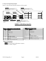
Protocol: RS-232C/422/485, 9600 baud rate, no parity, 8 data bits, 1 start bit, and 1 stop bit.
Connectors: Rear panel, DB-9 female
SWITCH Pinouts
Pino
outs (RS-232C/422/485)
Pin
CH1,CH2,CH3,CH4,BU
CH1,CH2,CH
H3,CH4,BU Pinouts
Pin
Function
Function
1
Rx-
1
Tx-
2
Rx+ (RS-232C)
2
Tx+ (RS-232C)
3
Tx+ (RS-232C)
3
Rx+ (RS-232C)
4
Tx-
4
Rx-
5
GND
5
GND
6
Alarm Relay: Common
6
Alarm Relay: Common
7
Alarm Relay: Normally Open
7
Alarm Relay: Normally Open
8
Not Used
8
Not Used
9
Alarm Relay: Normally Closed
9
Alarm Relay: Normally Closed
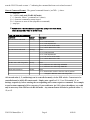
B) Status Requests Table 1.1 lists the status requests for the 2582-324 and briefly describes them
*
PLEASE NOTE: The two character {aa}(00-31) prefix, in the table below,
should be used ONLY when in RS-485 mode.
TABLE 1.1 2582-324 Status Requests
Command
Syntax *
Description
Command Status
{aaS1}
Returns {aaS1bcdefghi} where:
• b = BACK-UP Status
0 = Normal, no channels backed up
1 = CH1 is currently backed up
2 = CH2 is currently backed up
• c = CH1 Status -- 0 = protected, 1 = unprotected
• d = CH1 Mode -- 0 = AUTO, 1 = MANUAL, 2 = REMOTE
• e = CH2 Status -- 0 = protected, 1 = unprotected
• f = CH2 Mode -- 0 = AUTO, 1 = MANUAL, 2 = REMOTE
• g = CH1 Alarm -- 0 = normal, 1 = alarm
• h = CH2 Alarm -- 0 = normal, 1 = alarm
• i = BACK-UP Alarm -- 0 = normal, 1 = alarm
• j = Power Supply A Alarm -- 0 = normal, 1 = alarm
• k = Power Supply B Alarm -- 0 = normal, 1 = alarm
Min. Auto Switching Status
{aaS5}
Returns {aaS5b} where:
• b = Minimum Auto Switching mode status
0 = Normal, Min. Auto Switching OFF
1 = Min. Auto Switching ON
C) Commands Table 1.2 lists the commands for the 2582-324 and briefly describes them. After a command is
2582-324 Manual,Rev. C
Page 5
8/05/09