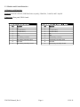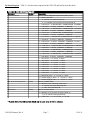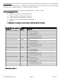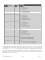
1
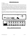
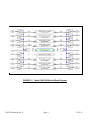
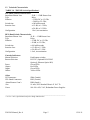
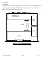
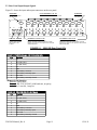
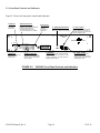
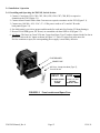
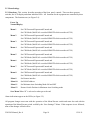
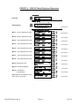
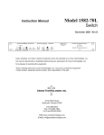
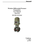
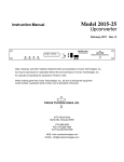
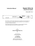
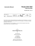
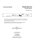
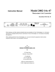
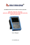
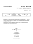
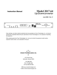
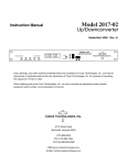
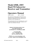
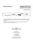
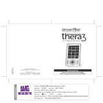
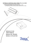
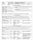
Model 2582-282
Instruction Manual
Backup Switch, 1 for 8
December 2011, Rev. 0
MODEL 2582
SWITCH
CROSS TECHNOLOGIES INC.
SWITCH
UNIT STATUS
1 2 3 4 5 6 7 8 BU
ALARM
PSA
PSB
ALARM
OFFLINE
ONLINE
PROT
MODE
1
2
3
4
5
6
7
8 BU
P P P P P P P P 2
A M A A A A A A M
MENU
PROTECTION STATUS
EXECUTE
Data, drawings, and other material contained herein are proprietary to Cross Technologies, Inc.,
but may be reproduced or duplicated without the prior permission of Cross Technologies, Inc.
for purposes of operating the equipment. Printed in USA.
When ordering parts from Cross Technologies, Inc., be sure to include the equipment
model number, equipment serial number, and a description of the part.
CROSS TECHNOLOGIES, INC.
6170 Shiloh Road
Alpharetta, Georgia 30005
(770) 886-8005
FAX (770) 886-7964
Toll Free 888-900-5588
WEB: www.crosstechnologies.com
E-MAIL: [email protected]
INSTRUCTION MANUAL
MODEL 2582-282 Switch
TABLE OF CONTENTS
Warranty
1.0 General
1.1 Equipment Description
1.2 Technical Characteristics
1.3 Monitor & Control Interface
2.0 Installation
2.1 Mechanical
2.2 Rear I/O’s
2.3 Front Panel Controls, Indicators
2.4 Operation
2.5 Menu Settings
3.0 Environmental Use Information
PAGE
2
3
3
5
6
10
10
11
12
13
14
18
WARRANTY - The following warranty applies to all Cross Technologies, Inc. products.
All Cross Technologies, Inc. products are warranted against defective materials and
workmanship for a period of one year after shipment to customer. Cross Technologies,
Inc.’s obligation under this warranty is limited to repairing or, at Cross Technologies, Inc.’s
option, replacing parts, subassemblies, or entire assemblies. Cross Technologies, Inc. shall
not be liable for any special, indirect, or consequential damages. This warranty does not
cover parts or equipment which have been subject to misuse, negligence, or accident by the
customer during use. All shipping costs for warranty repairs will be prepaid by the
customer. There are not other warranties, express or implied, except as stated herein.
CROSS TECHNOLOGIES, INC.
6170 Shiloh Road
Alpharetta, Georgia 30005
(770) 886-8005
FAX (770) 886-7964
Toll Free 888-900-5588
WEB: www.crosstechnologies.com
E-MAIL: [email protected]
2582-282 Manual_Rev.0
Page 2
12/19/11
MODEL 2582-282 Switch, 1 for 8
1.0 General
1.1 Equipment Description
The 2582-282 1 for 8 Switch with Backup Controller provides Auto or Manual backup protection for up to 8
converters by relay switching IF and RF signals from one backup unit to any of 8 on-line units. The controller
in the 2582-282 monitors alarms and settings of the on-line units and sets the backup unit to the parameters of
the unit being backed up prior to backing it up. The 2582-282 works with standard Cross Up or
Downconverters by polling their monitor and control ports on a periodic basis. A defective unit’s inputs and
outputs are switched from the failed unit to the backup when a failure occurs either automatically or manually.
“On-line”, “Off-line” and “not used” modes can be programmed for each converter. Alarms are contact closures
to ground. Status of the 2582-282 is reported via a serial data stream (Ethernet, Optional) and a contact closure
to ground on alarm.
All user settings of the switch are stored in nonvolatile ROM and on power up the 2582-282 polls all units.
Manual Select is controlled by the multi-function switches on the front panel. LEDs indicate alarm and switch
conditions. The unit is powered by two 100-240 ±10% VAC redundant power supplies, and housed in a 2RU
chassis.
MODEL 2582
SWITCH
CROSS TECHNOLOGIES INC.
SWITCH
UNIT STATUS
1 2 3 4 5 6 7 8 BU
ALARM
PSA
PSB
ALARM
OFFLINE
ONLINE
PROT
MODE
1
2
3
4
5
6
7
8 BU
P P P P P P P P 2
A M A A A A A A M
MENU
PROTECTION STATUS
EXECUTE
FRONT PANEL
J10
SWITCH
M&C
CH1
CH2
CH3
CH4
CH5
CH6
CH7
CH8
BU
•••••
••••
•••••
••••
•••••
••••
•••••
••••
•••••
••••
•••••
••••
•••••
••••
•••••
••••
•••••
••••
•••••
••••
J61
J62
J63
J64
J65
J66
J68
J69
GND
AC A
AC B
J67
J21
J31
J22
J32
J23
J33
J24
J34
J25
J35
J26
J36
J27
J37
J28
J38
J29
J39
J1
J11
J2
J12
J3
J13
J4
J14
J5
J15
J6
J16
J7
J17
J8
J18
J9
J19
RF
IF
CONV
IN/OUT
CONV
IN/OUT
CONV
IN/OUT
CONV
IN/OUT
CONV
IN/OUT
CONV
IN/OUT
CONV
IN/OUT
CONV
IN/OUT
CONV
IN/OUT
REAR PANEL
FIGURE 1.1
2582-282 Manual_Rev.0
Model 2582-282 Front and Rear Panels
Page 3
12/19/11
FIGURE 1.2
2582-282 Manual_Rev.0
Model 2582-282 Switch Block Diagram
Page 4
12/19/11
1.2 Technical Characteristics
TABLE 1.0 2582-282 Switch Specifications*
IF/L-Band Switch Characteristics
Impedance/Return Loss
50 Ω / > 12 dB Return Loss
Type
Relay
Isolation
> 55 dB, DC to 1.5 GHz
> 50 dB, to 2.2 GHz;
Switch time
≤ 100 milliseconds
Insertion Loss
≤ 1.5 dB, to 1.5 GHz;
≤ 2.0 dB, to 2.2 GHz
Configuration
1 for 8, no termination
RF/L-Band Switch Characteristics
Impedance/Return Loss
50 Ω / > 12 dB Return Loss
Type
Relay
Isolation
> 55 dB, DC to 1.5 GHz
> 50 dB, to 2.2 GHz;
Switch time
≤ 100 milliseconds
Insertion Loss
≤ 1.5 dB, to 1.5 GHz;
≤ 2.0 dB, to 2.2 GHz
Configuration
1 for 8, no termination
Controls, Indicators
Manual Selection
Remote Selection
Power
Alarms
Online
Offline
Push-button switches
RS 232C (Optional RS 422/485
Option Q; Ethernet Option W8)
Green LEDs
Red LEDs
Green LEDs
Yellow LEDs
Other
RF Connectors
IF/L-Band Connectors
Alarm/Remote Conn’s
Size
Power
SMA (female)
BNC (female)
DB9 (female)
19 inch, 2RU Standard Chassis X 16.0” D
100-240 ±10% VAC, Redundant Power Supplies
____________________________________________________________________
*+10˚C to +40˚C; Specifications subject to change without notice
2582-282 Manual_Rev.0
Page 5
12/19/11
1.3 Monitor and Control Interface
A) Remote serial interface
Protocol: RS-232C/422/485, 9600 baud rate, no parity, 8 data bits, 1 start bit, and 1 stop bit.
Connectors: Rear panel, DB-9 female
SWITCH Pinouts
Pinou
uts (RS-232C/422/485)
Pin
CH1,CH2,CH3,CH4,CH5,CH6,CH7,CH8,
CH1,CH2,CH3,,CH4,CH5,CH6,CH7,CH8, BU Pinouts
Function
Pin
Function
1
Rx-
1
Tx-
2
Rx+ (RS-232C)
2
Tx+ (RS-232C)
3
Tx+ (RS-232C)
3
Rx+ (RS-232C)
4
Tx-
4
Rx-
5
GND
5
GND
6
Alarm Relay: Common
6
Alarm Relay: Common
7
Alarm Relay: Normally Open
7
Alarm Relay: Normally Open
8
Not Used
8
Not Used
9
Alarm Relay: Normally Closed
9
Alarm Relay: Normally Closed
2582-282 Manual_Rev.0
Page 6
12/19/11
B) Status Requests Table 1.1 lists the status requests for the 2582-282 and briefly describes them.
TABLE 1.1 2582-282 Status Requests
Command
Syntax *
Description
Command Status
{aaS1}
Returns {aaS1bcdefghijklmnopqrstuvwxyzABC} where:
• b = BACK-UP Status
0 = Normal, no channel backed up
1 - 8 = number of the channel currently backed up
• c = CH1 Status -- 0=PROTECTED, 1=UNPROTECTED, 2=UNUSED
• d = CH1 Mode -- 0=AUTO, 1=MANUAL, 2=REMOTE
• e = CH2 Status -- 0=PROTECTED, 1=UNPROTECTED, 2=UNUSED
• f = CH2 Mode -- 0=AUTO, 1=MANUAL, 2=REMOTE
• g = CH3 Status -- 0=PROTECTED, 1=UNPROTECTED, 2=UNUSED
• h = CH3 Mode -- 0=AUTO, 1=MANUAL, 2=REMOTE
• i = CH4 Status -- 0=PROTECTED, 1=UNPROTECTED, 2=UNUSED
• j = CH4 Mode -- 0=AUTO, 1=MANUAL, 2=REMOTE
• k = CH5 Status -- 0=AUTO, 1=MANUAL, 2=REMOTE, 2=unused
• l = CH5 Mode -- 0=AUTO, 1=MANUAL, 2=REMOTE
• m = CH6 Status -- 0=PROTECTED, 1=UNPROTECTED, 2=UNUSED
• n = CH6 Mode -- 0=AUTO, 1=MANUAL, 2=REMOTE
• o = CH7 Status -- 0=PROTECTED, 1=UNPROTECTED, 2=UNUSED
• p = CH7 Mode -- 0=AUTO, 1=MANUAL, 2=REMOTE
• q = CH8 Status -- 0=PROTECTED, 1=UNPROTECTED, 2=UNUSED
• r = CH8 Mode -- 0=AUTO, 1=MANUAL, 2=REMOTE
• s = CH1 Alarm -- 0 = normal, 1= alarm
• t = CH2 Alarm -- 0 = normal, 1 = alarm
• u = CH3 Alarm -- 0 = normal, 1 = alarm
• v = CH4 Alarm -- 0 = normal, 1 = alarm
• w = CH5 Alarm -- 0 = normal, 1 = alarm
• x = CH6 Alarm -- 0 = normal, 1 = alarm
• y = CH7 Alarm -- 0 = normal, 1 = alarm
• z = CH8 Alarm -- 0 = normal, 1 = alarm
• A = BACK-UP Alarm -- 0 = normal, 1 = alarm
• B = Power Supply A Alarm -- 0 = normal, 1 = alarm
• C = Power Supply B Alarm -- 0 = normal, 1 = alarm
Min. Auto Switching Status
{aaSM}
Returns {aaSMb} where:
• b = Minimum Auto Switching mode status
0 = Normal, Min. Auto Switching OFF
1 = Min. Auto Switching ON
Hold Status
{aaSH}
Returns {aaSHbc} where:
• b = Number of the channel currently backed up
(0 if no channel is being backed up)
• C = Hold state -- 0 = not on hold; 1 = on hold
* PLEASE NOTE: The Address (aa) should only be used when RS-485 is selected.
2582-282 Manual_Rev.0
Page 7
12/19/11
C) Commands Table 1.2 lists the commands for the 2582-282 and briefly describes them. After a command is
sent the 2582-282 sends a return “>” indicating the command has been received and executed. If the command
has an error (e.g., invalid value), the ‘>’ character will not be returned.
General Command Format - The general command format is {aaCND...}, where:
{ = start byte
aa = address of unit (only used if in RS-485 mode)
C = 1 character, either C (command) or S (status)
N = 1-digit command or status number, 1 through 9
D = 1 character or more of data (depends on command)
} = stop byte
* PLEASE NOTE: The Address (aa) should only be used when RS-485 is selected.
Table 1.2 2582-282 Commands
Comman
nds
Command
Syntax*
Description
Set CH1 Status and Mode
{aaC1xy}
where:
• x = 0; CH1 Protected
• x = 1; CH1 Unprotected
• x = 2; CH1 Unused
• y = 0; set CH1 to AUTO mode
• y = 1; switch BACK-UP to CH1
Set CH2 Status and Mode
{aaC2xy}
where:
• x = 0; CH2 Protected
• x = 1; CH2 Unprotected
• x = 2; CH2 Unused
• y = 0; set CH2 to AUTO mode
• y = 1; switch BACK-UP to CH2
Set CH3 Status and Mode
{aaC3xy}
where:
• x = 0; CH3 Protected
• x = 1; CH3 Unprotected
• x = 2; CH3 Unused
• y = 0; set CH3 to AUTO mode
• y = 1; switch BACK-UP to CH3
Set CH4 Status and Mode
{aaC4xy}
where:
• x = 0; CH4 Protected
• x = 1; CH4 Unprotected
• x = 2; CH4 Unused
• y = 0; set CH4 to AUTO mode
• y = 1; switch BACK-UP to CH4
(Continued on page 9...)
2582-282 Manual_Rev.0
Page 8
12/19/11
Table 1.2 2582-282 Commands
Comman
nds (continued from page 8)
Command
Syntax*
Description
Set CH5 Status and Mode
{aaC5xy}
where:
• x = 0; CH5 Protected
• x = 1; CH5 Unprotected
• x = 2; CH5 Unused
• y = 0; set CH5 to AUTO mode
• y = 1; switch BACK-UP to CH5
Set CH6 Status and Mode
{aaC6xy}
where:
• x = 0; CH6 Protected
• x = 1; CH6 Unprotected
• x = 2; CH6 Unused
• y = 0; set CH6 to AUTO mode
• y = 1; switch BACK-UP to CH6
Set CH7 Status and Mode
{aaC7xy}
where:
• x = 0; CH7 Protected
• x = 1; CH7 Unprotected
• x = 2; CH7 Unused
• y = 0; set CH7 to AUTO mode
• y = 1; switch BACK-UP to CH7
Set CH8 Status and Mode
{aaC8xy}
where:
• x = 0; CH8 Protected
• x = 1; CH8 Unprotected
• x = 2; CH8 Unused
• y = 0; set CH8 to AUTO mode
• y = 1; switch BACK-UP to CH8
Set Min. Auto Switching Mode {aaCMx}
where:
• x = 0; Minimum Auto Switching DISABLED
• x = 1; Minimum Auto Switching ENABLED
Restore Switch Position
{aaCHx}
where:
• x = 0; Remove the 'hold' after the switch position
changed in Minimum Auto Switching mode
All external units (backup and channels 1 thru 8) can be controlled remotely via the 2582 switch. Converters to
be controlled must be in remote mode. Simply enter a prefix of *0,*1,*2,*3,*4,*5,*6,*7,*8 for units where *0
is the backup, 1, 2, 3, 4, 5, 6, 7, 8, respectively, before entering the corresponding unit’s status request or
command. For example, to send a status command of S1 to converter #1 you would enter {aa*1S1}, where the
address, aa, would only be necessary if the 2582 were in RS-485 mode. Any returned status will also be
prefixed with a *0,*1,*2,*3,*4,*5,*6,*7,*8.
2582-282 Manual_Rev.0
Page 9
12/19/11
2.0 Installation
2.1 Mechanical
The 2582-282 consists of one IF or L-Band Switching PCB, one Controller PCB, and one interface PCB housed
in a 2 RU (3 1/2 inch high) by 16 inch deep chassis. Two redundant switching, ± 12, +24, +5 VDC power
supplies provide power for the assembly. The 2582-282 can be secured to a rack using the 4 holes on the front
panel. Figure 2.0 shows how the 2582-282 is assembled.
Interface PCB on Top
IF Switch PCB on Bottom
POWER
SUPPLY
2
Interconnect
Cables
POWER
SUPPLY
1
Controller
PCB
FIGURE 2.0
2582-282 Manual_Rev.0
2582-282 Mechanical Assembly
Page 10
12/19/11
2.2 Rear Panel Input/Output Signals
Figure 2.1 shows the input and output connectors on the rear panel.
SWITCH M&C
Monitor and controls for
the 2582 switch.
J10
CH1 to CH8 MONITOR - J62 - J69
Monitors for an alarm from Unit #1 to Unit #8.
SWITCH
M&C
CH1
CH2
CH3
CH4
CH5
CH6
CH7
CH8
BU
•••••
••••
•••••
••••
•••••
••••
•••••
••••
•••••
••••
•••••
••••
•••••
••••
•••••
••••
•••••
••••
•••••
••••
J61
J62
J63
J64
J65
J66
J68
J69
GND
AC A
BU MONITOR
Monitors for an alarm
from Back-Up unit.
AC B
J67
J21
J31
J22
J32
J23
J33
J24
J34
J25
J35
J26
J36
J27
J37
J28
J38
J29
J39
J1
J11
J2
J12
J3
J13
J4
J14
J5
J15
J6
J16
J7
J17
J8
J18
J9
J19
RF
IF
CONV
AC A, AC B - POWER IN
AC inputs for redundant
switching power supplies.
100-240 ±10% VAC,
47-60 Hz.
IN/OUT
CONV
IN/OUT
CONV
IN/OUT
CONV
IN/OUT
CONV
IN/OUT
RF SIGNALS -J21-J29 & J31-J39
Signals to/from Unit #1 to #8 and the
Backup Unit CONV goes to the up/down converter
IN/OUT is the input to or the output from the converter.
SMA (female) 50Ω.
FIGURE 2.1
CONV
IN/OUT
CONV
IN/OUT
CONV
IN/OUT
CONV
IN/OUT
IF 2 SIGNALS J1-J9 & J11-J19
Signals to/from Unit #1 to #8 and the
Backup Unit CONV goes to the up/down converter
IN/OUT is the input to or the output from the converter.
BNC (female) 50Ω.
2582-282 Rear Panel I/Oʼs
TABLE 2.1 SWITCH
SWITCH Pinouts (RS-232C/422/485)
Pin
Function
1
Rx-
2
Rx+ (RS-232C)
3
Tx+ (RS-232C)
4
Tx-
5
GND
6
Alarm Relay: Common
7
Alarm Relay: Normally Open
8
Not Used
9
Alarm Relay: Normally Closed
*Remote Serial Interface
Interface: DB-9 Male
Protocol: RS-232C/422/485, 9600 baud rate, no parity,
8 data bits, 1 start bit, 1 stop bit.
TABLE 2.2 CH1,CH2,CH3,CH4,BU Pinouts
Pin
Function
1
Tx-
2
Tx+ (RS-232C)
3
Rx+ (RS-232C)
4
Rx-
5
GND
6
Alarm Relay: Common
7
Alarm Relay: Normally Open
8
Not Used
9
Alarm Relay: Normally Closed
2582-282 Manual_Rev.0
Page 11
12/19/11
2.3 Front Panel Controls and Indicators
Figure 2.2 shows the front panel controls and indicators.
ALARM LED
Illuminates red
if the switch
malfunctions
ALARM STATUS LEDs
Red LEDs remains on if the
respective unit is alarmed. Red LED
blinks if the respective unit
is not alarmed but the switch
cannot communicate to it via M&C.
Back-Up LEDs
Green LED for BU
indicates
a unit is being
backed up.
S1 - MENU/EXECUTE BUTTON
Press this to get into Program
Mode and to execute any changes.
S2 - VERT. TOGGLE
Vertical toggle switch that controls
values in the Menu items when in
program mode. Does not function in
the normal display mode.
MODEL 2582
SWITCH
CROSS TECHNOLOGIES INC.
SWITCH
UNIT STATUS
1 2 3 4 5 6 7 8 BU
ALARM
PSA
PSB
PROT
MODE
ALARM
OFFLINE
ONLINE
1
POWER LEDs
Green LEDs indicate DC
voltage from each
power supply.
2
3
4
5
6
7
8
BU
ONLINE/OFFLINE LEDs
Green LEDs for CH1 to CH8
indicate they are online. Yellow
LEDs for CH1 to CH8 indicate
they are offline.
FIGURE 2.2
2582-282 Manual_Rev.0
P P P P P P P P 2
A M A A A A A A M
MENU
PROTECTION STATUS
EXECUTE
LCD DISPLAY
Display shows if CH1 to CH8 are protected
or not, what mode CH1to CH8 are in (AUTO,
MANUAL, REMOTE), and which channel is
being backed up (if any).
S3 - HORIZ. TOGGLE
Horizontal toggle switch that
controls which values are being
adjusted. Does not function in the
normal display mode.
2582-282 Front Panel Controls and Indicators
Page 12
12/19/11
2.4 Installation / Operation
2.4.1 Installing and Operating the 2582-282, Switch Section.
1. Connect Converters (CH1, CH2, CH3, CH4, CH5, CH6, CH7, CH8, BU) to respective
channels on the 2582 (Figure 2.1).
2. Connect Alarm/Control cables from Converters to respective monitors on the 2582 (Figure 2.1).
3. Connect two 100-240 ± 10% VAC, 47 - 63 Hz power cords to AC A and AC B on the
back panel (Figure 2.1).
4. Set which unit(s) you wish to protect and the mode for each unit (See Section 2.5 Menu Settings).
5. Be sure PSA & PSB (green, DC Power) are on and the red alarm LED is off (Figure 2.2).
6. AC Fuses - The fuses are 5 mm X 20 mm, 2 amp slow blow (Type T) and are inserted in the far slot in
the drawer below the AC inputs as shown in Figure 2.3. There is a spare fuse in the near slot.
If a fuse continues to open, the corresponding power supply is most likely defective.
FUSE DRAWER
SPARE FUSE
AC Fuse - 2 amp slow blow (Type T),
5 mm X 20 mm
INPUT
~
~
100-240± 10%VAC
47-63 Hz
2A MAX
FIGURE 2.3
2582-282 Manual_Rev.0
FUSE
TYPE T 2A GDC
250 VOLT
FOR 100 - 240 V~
Fuse Location and Spare Fuse
Page 13
12/19/11
2.5 Menu Settings
2.5.1 Functions - This section describes operation of the front panel controls. There are three operator
switches, the LCD display and alarm indicator LEDs. All functions for the equipment are controlled by these
components. The functions are (see Figure 2.4):
Power Up
Normal Display
Menu 1
Set CH1 Protected/Unprotected/Unused and
Set CH1 Mode (MANUAL overrides REMOTE which overrides AUTO)
Menu 2
Set CH2 Protected/Unprotected/Unused and
Set CH2 Mode (MANUAL overrides REMOTE which overrides AUTO)
Menu 3
Set CH3 Protected/Unprotected/Unused and
Set CH3 Mode (MANUAL overrides REMOTE which overrides AUTO)
Menu 4
Set CH4 Protected/Unprotected/Unused and
Set CH4 Mode (MANUAL overrides REMOTE which overrides AUTO)
Menu 5
Set CH5 Protected/Unprotected/Unused and
Set CH5 Mode (MANUAL overrides REMOTE which overrides AUTO)
Menu 6
Set CH6 Protected/Unprotected/Unused and
Set CH6 Mode (MANUAL overrides REMOTE which overrides AUTO)
Menu 7
Set CH7 Protected/Unprotected/Unused and
Set CH7 Mode (MANUAL overrides REMOTE which overrides AUTO)
Menu 8
Set CH8 Protected/Unprotected/Unused and
Set CH8 Mode (MANUAL overrides REMOTE which overrides AUTO)
Menu 9
Set Remote interface
Menu 10
Set RS-485 address
Menu 11
Set Minimum Auto Switching Mode ON and OFF
Menu 12
Restore Switch Position in Minimum Auto Switching mode
Save Menu When “R” is selected or when get to the end
Alarm indications appear on the LEDs (see figure 2.2).
All program changes must start with the operation of the Menu/Execute switch and must also end with the
operation of the Menu/Execute switch verified by the “Save Settings?” Menu. If this sequence is not followed,
none of the changes will take effect.
2582-282 Manual_Rev.0
Page 14
12/19/11
2.5.2. Power On Settings
NOTE: The last status of a unit is retained even when power is removed. When power is restored, the unit will
return to it's previous settings.
When power is first applied, the LCD display goes through six steps:
1. All alarm, offline & online LEDs are turned on. If any one does not come on,
there is a hardware fault that should be fixed.
2. The LCD goes black to show all segments are functioning.
3. The model number and software version will be displayed.
1
2
3
PROT
2582-282
MODE
Rev. 5.00
4
5
6
7
8
BU
PROTECTION STATUS
4. Green LEDs are lit in succession, 1 thru 8 and backup. This is the initial scan for
all channel settings.
5. All alarm, offline & online LEDs are set by the control program to reflect the
current states of the attached units.
6. The present protection state and mode of each channel/unit are shown.
1
2
3
4
5
6
7
8
BU
PROT
P
P
P
P
P
P
P
P
2
MODE
A
A
A
A
A
A
A
A
M
PROTECTION STATUS
The unit is now operational and ready for any changes the operator may desire.
2.5.3 Control Switches
1. Menu/Execute - Any change to the programming of the unit must be initiated by pressing the
Menu/Execute switch and completed by pressing the Menu/Execute switch.
2. Horizontal Switch - This switch is mounted so its movement is horizontal and moves the cursor left or
right.
3. Vertical Switch - This switch is mounted so its movement is vertical, and changes settings in each menu.
2.5.4 Alarm Indications
An alarm condition will occur if the corresponding unit’s local oscillator phase lock loop (PLL) comes out of
lock (when connected properly).
2582-282 Manual_Rev.0
Page 15
12/19/11
FIGURE 2.4
2582-282 Menu Display and Sequences
ON POWER UP
Power Up
PROT
MODE
2582-282
REV 5.00
NORMAL DISPLAY
Normal Display
PROT
MODE
1 2
3 4
P P
A A
P P P P P P
A A A A A A A
5
6
7 8 BU
PUSH BUTTON
PROTECTION STATUS
PUSHING MENU/EXECUTE SEQUENCE
Menu 1 Set CH1 protection & mode
= = = = CH1 = = = =
Protected
Auto
R
Menu 2 Set CH2 protection & mode
= = = = CH2 = = = =
Protected
Auto
R
Menu 3
Menu 4
Set CH3 protection & mode
Set CH4 protection & mode
SCROLL
SCROLL
= = = = CH3 = = = =
Protected
Auto
= = = = CH4 = = = =
Protected
Auto
SCROLL <>
SCROLL
R
SCROLL
Set CH5 protection & mode
= = = = CH5 = = = =
Protected
Auto
R
Menu 6
Set CH6 protection & mode
= = = = CH6 = = = =
Protected
Auto
R
Menu 7
Set CH7 protection & mode
= = = = CH7 = = = =
Protected
Auto
R
Remote Interface
RS232
R
Menu 10 Set RS-485 Address
RS485 Address = 00
R
Minimum Auto
Switching
OFF
SCROLL
Save? When “R” is selected from any
above menu or at the end.
SAVE SETTINGS?
2582-282 Manual_Rev.0
PUSH BUTTON
PUSH BUTTON
PUSH BUTTON
SCROLL <>
PUSH BUTTON
SCROLL <>
SCROLL
Page 16
PUSH BUTTON
SCROLL <>
SCROLL
Y N
PUSH BUTTON
SCROLL <>
SCROLL
R
PUSH BUTTON
SCROLL <>
SCROLL
Menu 11 Set Minimum
Auto Switching
PUSH BUTTON
SCROLL <>
SCROLL
Menu 9 Set Remote mode
PUSH BUTTON
SCROLL <>
SCROLL
R
PUSH BUTTON
SCROLL <>
SCROLL
= = = = CH8 = = = =
Protected
Auto
Set CH8 protection & mode
PUSH BUTTON
SCROLL <>
SCROLL <>
Menu 5
Menu 8
SCROLL <>
PUSH BUTTON
12/19/11
2.5.5 Minimum Auto Switching Mode
Enabling and Disabling
The Minimum Auto Switching mode is enabled and disabled via a front panel menu. The Minimum Auto
Switching mode can also be enabled and disabled via the following M&C command:
{CMx}
Where x=1 to enable and x=0 to disable.
The status of the 2582-282 Minimum Auto Switching mode setting can be queried by sending the following
command:
{SM}
Which returns {SMx} where x=1 if enabled and x=0 if disabled.
Operation
In the Minimum Auto Switching mode the switch will remain in a backup state after an alarm event - even if
the alarm event that caused the unit to switch has been cleared. The main display will show an “H” (hold)
under the BU MODE after an alarm causes the switch to change states while in the Minimum Auto Switching
mode. The unit can be restored to the normal state via a front panel restore command or an M&C restore
command. The front panel Restore Switch menu appears after the Minimum Auto Switching mode ON/OFF
menu only if the Minimum Auto Switching mode is on. The backup can also be released from its hold state via
the following M&C command:
{CHx}
Where x = 0 to restore.
NOTE: The switch will automatically restore - as soon as the alarm event that caused the unit to switch has
been cleared - IF the Minimum Auto Switching mode is disabled either via the front panel setting or by the
M&C command.
2582-282 Manual_Rev.0
Page 17
12/19/11
2.5.6 Switch Actions in Response to Various Conditions
General Operation Description
If one of channels 1 thru 8 is alarmed, the 2582 automatically switches the RF signals from that unit to the
backup unit. I.e., the alarmed unit is now offline and the backup unit is now online operating in place of the
alarmed unit. If more than one unit is alarmed, only the highest priority unit is backed up. The priority is based
on the channel number where 1 is the highest priority and 8 is the lowest.
However, if a unit’s settings have never been successfully obtained by the 2582 since being powered up, then
the 2582 does not have settings with which to program the backup unit for that channel. Therefore, if the 2582
does not have settings for an alarmed unit, that alarmed unit cannot be backed up.
Any one of the following conditions will prevent an alarmed unit from being automatically backed up.
a)
b)
c)
d)
e)
f)
g)
The 2582 never successfully obtained settings from the unit.
The unit’s protection setting is not PROTECTED.
The unit’s mode setting is not AUTO.
The backup unit is alarmed.
A unit of higher priority is already being backed up.
Some other unit is being forcefully backed up via MANUAL or REMOTE.
Minimum auto switching is on and is holding another channel in backup until released.
Specifics
The following describes specific conditions in more detail, the response of the 2582 and any changes to the
display or LEDs to indicate the stated condition.
1. Channel i is alarmed.
• Highest priority unit is backed up. Channel i has higher priority than channel j if i < j.
• Remaining units are online, even if alarmed.
2. Failure to obtain settings from unit i at power up.
• Red LED i blinks.
• Unit i can not be backed up since there are no settings with which to program the BU unit.
3. Failure to detect unit i’s communication after power up.
• In firmware, unit i is declared “not connected”.
• Red LED i blinks.
• No other corrective action is taken.
• If alarmed & the highest priority channel, unit i will be backed up using the latest
settings successfully obtained from the unit.
(continued ...)
2582-282 Manual_Rev.0
Page 18
12/19/11
4. Failure to successfully send settings to unit i when switching i back online from being backed up.
• No corrective action is taken.
• If preempted by a higher-priority unit needing to be backed up, unit i is switched online anyway.
• If alarmed & the highest priority channel, unit i will be backed up using the latest
settings successfully obtained from the unit.
5. Backup unit is alarmed.
• No unit can be backed up.
• Any channel being backed up is switched back online at the time the BU unit alarms.
6. Channel i is set for “UNUSED”.
• ‘X’ appears on the display under the channel number for both Prot. & Mode.
• Unit is not considered for backing up.
• LEDs for that unit are all turned off.
2582-282 Manual_Rev.0
Page 19
12/19/11
3.0 Environmental Use Information
A. Rack-Mounting - To mount this equipment in a rack, please refer to the installation instructions
located in the user manual furnished by the manufacturer of your equipment rack.
B. Mechanical Loading - Mounting of equipment in a rack should be such that a hazardous condition
does not exist due to uneven weight distribution.
C. Elevated Operating Ambient Temperature - If installed in a closed or multi-unit rack assembly,
the operating ambient temperature of the rack may be greater than room ambient temperature.
Therefore, consideration should be given to Tmra.
D. Reduced Air Flow - Installation of the equipment in a rack should be such that the amount of air flow
required for safe operation of the equipment is not compromised. Additional space between units
may be required.
E. Circuit Overloading - Consideration should be given to the connection of the equipment to the supply
circuit and the effect that overloading of circuits could have on over current protection and supply wiring.
Appropriate consideration of equipment name plate rating should be used when addressing this concern.
F. Reliable Earthing - Reliable earthing of rack-mounted equipment should be maintained.
Particular attention should be given to supply connections other than direct connection to the
Branch (use of power strips).
G. Top Cover - There are no serviceable parts inside the product so, the Top Cover should not be removed.
If the Top Cover is removed the ground strap and associated screw MUST BE REINSTALLED
prior to Top Cover screw replacement. FAILURE TO DO this may cause INGRESS and/or EGRESS
emission problems.
2582-282 Manual_Rev.0
Page 20
12/19/11
CROSS TECHNOLOGIES, INC.
6170 Shiloh Road
Alpharetta, Georgia 30005
(770) 886-8005
FAX (770) 886-7964
Toll Free 888-900-5588
WEB: www.crosstechnologies.com
E-MAIL: [email protected]
Printed in USA
2582-282 Manual_Rev.0
Page 21
12/19/11