1
2.0 Installation
2.1 Mechanical
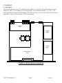
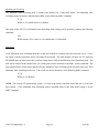
The 2582-324 consists of two IF or L-Band Switching PCBs, one Controller PCB, and two baseball switches
housed in a 2 RU (3 1/2 inch high) by 16 inch deep chassis. Two redundant switching, ± 12, +24, +5 VDC
power supplies provide power for the assembly. The 2582-324 can be secured to a rack using the 4 holes on the
front panel. Figure 2.0 shows how the 2582-324 is assembled.
IF SWITCH
PCB
POWER
SUPPLY
B
SWITCH
SWITCH
POWER
SUPPLY
A
CONTROLLER
PCB
FIGURE 2.0 2582-324 Mechanical Assembly
2582-324 Manual,Rev. C
Page 7
8/05/09