1
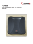
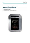
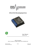
OEM 100
User Manual
Figure 1: OEM 100 Module with HG Rectangular Antenna Board
Revision History
Revision History
Release Version
Date
Revision Description
Authors
Version 1.0
07/20/09
Initial Release
Bryan Hoff and Jeremy Morton
Version 1.1
07/30/10
Feature updates
Bryan Hoff
Version 1.2
08/05/10
Overhaul of document
Bryan Hoff
Version 1.3
08/17/10
Updated graphics
Bryan Hoff
Version 1.5
09/01/10
Applied XceedID branding
Marian Sasso
Contents
Revision History....................................................................................................................................................... 2
General Description................................................................................................................................................. 3
Specifications........................................................................................................................................................... 4
Physical Dimensions........................................................................................................................................... 4
Electrical Specifications....................................................................................................................................... 4
Card Specifications....................................................................................................................................... 5
Card Technologies Supported....................................................................................................................... 5
Connector Specifications.............................................................................................................................. 6
Operational Behavior............................................................................................................................................... 7
Communication.................................................................................................................................................... 7
Serial Communication Parameters............................................................................................................... 7
Other Parameters.......................................................................................................................................... 7
RF Field............................................................................................................................................................... 7
Diagnostic LEDs.................................................................................................................................................. 8
Design Considerations............................................................................................................................................ 9
Cable Selection................................................................................................................................................... 9
Mounting Consideration....................................................................................................................................... 9
EMI Design Considerations............................................................................................................................... 11
Design References............................................................................................................................................ 11
Appendix A: Terms and Abbreviations ............................................................................................................... 12
Appendix B: Example RS485 Communication.................................................................................................... 14
RS485 POLL Command and ACK response.............................................................................................. 14
RS485 POLL Command............................................................................................................................. 15
RS485 ACK Response .............................................................................................................................. 16
RS485 End of POLL Command – Begin ACK Response........................................................................... 17
Appendix C: Example TTL (3.3v) Serial Communication.................................................................................... 18
TTL POLL Command.................................................................................................................................. 18
TTL ACK Response.................................................................................................................................... 18
Contact Information............................................................................................................................................... 19
2
General Description
General Description
The OEM 100 Module is a multi-tech ISO14443 and ISO15963 contactless Card Access Reader. The included hardware
and firmware will enable the use of many 125 kHz and 13.56 MHz cards and applications. It is designed to allow the
Design Engineer to easily integrate the module into an application/system.
The OEM 100 Module architecture consists of 2 PCB boards. One of the PCBs is the ‘brains’ of the system, referred
to as the Main Logic Board. The other PCB is the Antenna Board which will have both the 13.56 MHz and the 125 kHz
antennas. There are two choices for the antenna shape, one is rectangular and the other square.
3
Specifications
Specifications
Physical Dimensions
ÎÎ
Images not to scale.
Main Logic Board
Antenna Board #1 HG Rectangular
Antenna Board #2 Square
1.4”W x 2.05”L x .315”T
1.35”W x 3.6”L x 0.2”T
2.85”W x 2.83”L x 0.2”T
Figure 2: OEM 100 Module
Figure 3: HG Rectuglar Antenna
Figure 4: Square Antenna
Electrical Specifications
Symbol
Parameter
Min
Typical
Max
Units
T
Operating Temperature
-35
0
65
Celsius
F
Frequency
Vin
Voltage Input
16
Volts
IAVG
Average System Current
IMAX
Maximum System Current
WOL
Wiegnd Output Logic Low
0
WOH
Wiegand Output Logic High
2.65
RSOL
RS485 Output Logic Low
0
RSOH
RS485 Output Logic High
2.65
TTLOL
TTL Output Logic Low
0
TTLOH
TTL Output Logic High
2.65
II/O
Output Current on I/O pins
0
4
125kHz and 13.56 MHz
5
95
mAmps
180
mAmps
.4
Volts
3.6
Volts
.495
Volts
3.6
Volts
.495
Volts
3.3
3.6
Volts
4
25
mAmps
3.3
3.3
Specifications
Card Specifications
Card Read Ranges
Card Frequency
Card Type
Read Range
125 kHz
ASK, FSK
Up to 4.5” (11.4 cm)
13.56MHz
ISO 15693
Up to 3.0” (7.6 cm)
13.56MHz
ISO 14443A MIFARE® Standard
Up to 2.0” (5.1 cm)
13.56 MHz
ISO 14443A MIFARE® DESFire EV1
Up to 1.5” (3.8 cm)
Card Technologies Supported
125kHz Technologies
•
•
•
•
GE®/CASI® Proximity
HID® Proximity (Except Long Format)
AWID® Proximity
LenelProx®
13.56MHz Technologies
•
•
•
•
•
•
ISO14443 MIFARE DESFire™ EV1 with PACSA enabled (format in the card – up to 48 bits)
ISO14443 Secure MIFARE® Classic:
• XceedID™ MIFARE® app enabled (format in the card – up to 48 bits)
• OESM (dormant – ready to be enabled by end-user)
ISO14443 PIV enabled 75-bit format (other formats available)
iClass/Inside UID enabled 40-bit format
ISO15693 UID enabled 40-bit format
ISO14443 UID disabled (can be enabled if PIV, EV1 and MIFARE® are all disabled)
5
Specifications
Connector Specifications
J1 and J2 are both 2mm through hole interfaces. These are used for 125kHz antenna and the 13.56MHz antenna,
respectively. J3 is a customer accessible connector for integrating the OEM 100 into the system builders design.
Connector J1 (2 PIN 125 kHz Antenna)
Pin 1
Input (coil)
Pin 2
Output (coil)
Connector J2 (5 PIN 13.56 MHz Antenna)
Pin 1
13.56 MHz RF Out
Pin 2
Ground
Pin 3
13.56 MHz RF Return
Pin 4
Ground
Pin 5
13.56 MHz RF Out
Connector J3 (10 PIN OEM Interface)
PIN 1
VIN - Power In Accepts 5 to 16 Volts DC
PIN 2
U1 TX (TTL) Comm port, currently not used by Firmware
PIN 3
U1 RX (TTL) Comm port, currently not used by Firmware
PIN 4
U2 TX (TTL) Comm port, currently connected to RS-485 Chip
PIN 5
U2 RX (TTL) Comm port, currently connected to RS-485 Chip
PIN 6
RS-485 Z
PIN 7
RS-485 Y
PIN 8
Wiegand Data 0 Output (TTL)
PIN 9
Wiegand Data 1 Output (TTL)
PIN 10
Ground
6
Operational Behavior
Operational Behavior
Communication
The OEM 100 Module can communicate over the Wiegand Interface, the RS485 Interface, or over an UART-TTL Interface
(3.3V). The Data 0 and Data 1 Weigand output is the default communication channel. While in OSDP over serial
mode, the Weigand channel will be disabled. Currently, the RS485 and UART-TTL interfaces share the same physical
connection. The system developer will need to select which one they want active.
Configuring the Communication Channels
To select the Serial UART-TTL or the RS-485 over Interface, there is switch S1 located on the OEM 100 Module, just
above the 10 pin interface connector. For RS-485 set both switches to ON position (toward L5). To select the UART-TTL
interface, set both switches to the OFF position, toward R40. Depending on the hosts RS-485 implementation, some hosts
may need additional biasing to fully operate with the OEM100 Module.
Serial Communication Parameters
Address
0x00
Baud Rate
9600
Data Bits
8
Parity
No Parity
Stop Bit
1 Stop bit
Bit Time
104.667 µs
Byte Transmit Time
1.04 ms
Other Parameters
•
•
•
•
•
•
POLL command (7 bytes 0x53000700006046) takes 7.28ms to transmit (Host)
ACK response (7 bytes 0x538007000040E6) takes 7.28ms to transmit (XceedID reader)
Host should release transmit line 1ms after the last stop bit transmitted
Host should expect a response within 1ms - 6ms after releasing the transmit line
Host should allow at least 5ms before transmitting next command following a response
One byte:
• 10 bits total
• 1 start bit
• 8 data bits
• 1 stop bit
• No parity
RF Field
Every 100ms the RF field turns on and the reader polls for cards. The 13.56 MHZ field is on for approximately 42 ms in
the default reader configuration, which is maximum complexity. The 125 KHZ field is on for approximately 20 ms in the
default reader configuration, which is maximum complexity.
7
Operational Behavior
Diagnostic LEDs
The OEM 100 Module has two LEDs used for debugging and diagnostics. In the current firmware version, the behavior is
described in the table below.
Diagnostic OEM LED1
The LED is on if power is on (microcontroller is running)
The LED Flashes (fast on/off) as long as a card is in the field
3 slow flashes of the LED (during the power-up sequence) if the device is configured to read all UIDs (EV1, Mifare
Classic, and PIV all disabled)
When processing a configuration card, the LED turns off for a few seconds. This operation is always followed by the
power-up sequence
Diagnostic OEM LED2
The LED is on if the device is in OSDP mode (i.e. a valid OSDP message was received in the last 8 seconds)
In Wiegand mode, the LED is off normally, but flashes once with every Wiegand data transmission
8
Design Considerations
Design Considerations
This section will give the Design Engineer guidance on designing the OEM 100 module into his or her application.
Cable Selection
The interface cable between the OEM 100 Module and the end users system is a 10 pin connector. For this connection,
we suggest using a flat ribbon cable i.e. 3M (3625/10 100M), with a Tyco 1-440146-0 mating connector on it to mate
correctly with the OEM 100 Module.
Between the antenna board and the OEM 100 Module, the recommended cable should be no longer than 5 inches. The
wire gauge used should be 24 AWG. A set of cables to connect the antenna board will be supplied.
Mounting Consideration
The OEM 100 Module has 4 mounting holes. They are 0.12” in diameter, located one in each of the corners on of the
Main Logic PCB. In the image below, they are the green circles.
Figure 5: Mounting hole locations for the OEM 100
9
Design Considerations
The Rectangular HG Antenna Board has 4 mounting holes, 2 located on the ends of the PCB. They are 0.12” in diameter.
The other two are closer in and centered.
Figure 6: Mounting hole locations for HG Rectangular board
The Square Antenna Board has 5 mounting holes located 3 on the top end and 2 on the bottom end. They are 0.12” in
diameter.
Figure 7: Mounting hole locations for the square antenna
When mounting the Antenna Board, we suggest keeping it 1 cm or more from metal planes. Having a metal plane closer
than 1cm can lead to significant drops in read range performance.
10
Design Considerations
EMI Design Considerations
The OEM 100 Module has been pre-scanned and is compliant to FCC part 15. Although the OEM 100 Module does meet
FCC regulations, care must be taken when integrating it into a design. A key design tip to remember is to not route any of
the cables or antenna leads over or near clock sources, power sources, or high speed signals. A general rule of thumb is
to keep the cables routed at least 2 cm away from these types of signals.
Since the OEM 100 Module may be used in a multitude of applications, the responsibility to conform to local regulations is
left to the customer.
Design References
•
•
•
ISO14443
ISO15963
OSDP Specification
Application Note Micore Reader IC Family from NXP Semiconductors; Directly Matched Antenna Design
Documentation for related projects – See XceedID website (www.xceedid.com)
11
Appendix A: Terms and Abbreviations
Appendix A: Terms and Abbreviations
125 kHz:
Radio waves operating at 125 thousand cycles per second. This technology has historically been the standard in
proximity card/reader but is beginning to be replaced by faster, more secure 13.56 MHz technology.
13.56 MHz
Radio waves operating at 13.56 million cycles per second allowing read/write and secure, encrypted card and reader
communication. Because of the faster communication (compared to 125 kHz proximity technology) between a card
and reader, this technology is better suited for biometrics and secure, authenticated transactions.
ASK
Amplitude Shift Keying or modulation – Refers to the process of altering the height of the radio waves to signify the
zeros and ones in the binary communication – ASK is the most common form of modulation used in RFID. It is used in
both ISO 14443 and ISO 15693 specifications for reader to card communication.
CSN
Card Serial Number. Also known as the UID or Unique Identifier which is specified in the ISO specifications.
DESFire
A flexible, high security, ISO 14443 compliant, contactless smart card technology by NXP.
Firmware
Essentially software in the form of ROM or EEPROM that does not lose memory when power is not maintained.
FSK
Frequency Shift Keying or modulation – the process of altering the frequency of radio waves to signify the zeros and
ones in the binary communication.
ISO 14443
International standard regulating contactless, proximity technology, typically representing a read range distance up to
10 centimeters. The advantage products utilizing ISO 14443 have over those utilizing ISO 15693 is that the transaction
speed is faster, making security and transaction speed superior for large packets of information such as biometric
templates. ISO 14443 is actually divided into two sub-divisions of the standard, A & B. Without going into great detail,
ISO 14443A has grown to be the leading standard for access control and transportation and 14443B for banking.
ISO 15693
International standard regulating contactless, vicinity technology, typically representing a distance over 10 centimeters.
The advantage ISO 15693 has over ISO 14443 is greater convenience due to longer read ranges and less power
consumption.
MIFARE®
A proprietary contactless and dual interface smart card chip technology produced by NXP. Mifare is a well proven RF
communication technology for transmitting data between a card and a reader device and is fully compliant with ISO
14443A.
Modulation
The changing of radio waves in a specific manner in order to represent data.
12
Appendix A: Terms and Abbreviations
OSDP
Open Supervised Device Protocol is a communication protocol for interfacing one or more Peripheral Devices to a
Control Panel.
Protocol
How computers talk to each other – a communication system.
Proximity
A card/credential and reader system utilizing RFID technology in which the credential and reader utilize
microprocessors and antennas to communicate without having to come in contact with one another. This technology is
usually associated with 125 kHz frequency readers, the historical standard RFID technology in access control.
RS485
Standards for serial multipoint communications lines. These standards represent faster, two-way communication lines
rather than the standard Wiegand one-way communication lines prevalent in the access control industry.
Smart Card
A card or credential that contains a built-in microprocessor and memory used for identification and transactions in
a number of applications (security, financial, etc.). The card has read/write capability to transfer data from a reader
typically to a panel or computer.
UID
See CSN above
Wiegand Format
The most common data format in an access control system consisting of 26 bits of information.
13
Appendix B: Example RS485 Communication
Appendix B: Example RS485 Communication
RS485 POLL Command and ACK response
•
•
•
•
•
•
14
POLL command is generated by the host application
POLL command is preceded by 2 marking state (0xFF) characters
ACK response is generated by XceedID reader
ACK response is preceded by 2 marking state (0xFF) characters
Top trace (1) is non inverting (A)
Bottom trace (2) is inverting (B)
Appendix B: Example RS485 Communication
RS485 POLL Command
•
•
•
•
•
•
•
•
•
POLL command is generated by the host application
POLL command is preceded by two marking state (0xFF) characters
POLL command is 7 bytes (0x53000700006046)
POLL command transmission takes 7.28ms at 9600
Host releases transmission line (1) 1ms following the last stop bit
RS485 3.3v swing 1.125v low (2) and 4.500v high (3)
Bit time is 104us (4)
Top trace channel 1 is non inverting (A)
Bottom trace channel 2 is inverting (B)
15
Appendix B: Example RS485 Communication
RS485 ACK Response
•
•
•
•
•
•
•
•
•
16
ACK response is generated by XceedID reader
ACK response is preceded by two marking state (0xFF) characters
ACK response is 7 byte (0x538007000040E6)
ACK response transmission takes 7.28ms at 9600
XceedID reader releases transmission line (1) 1ms following the last stop bit
RS485 3.3v swing 10mv low (2) 3.400v high (3)
Bit time is 104us (4)
Top trace (1) is non inverting (A)
Bottom trace (2) is inverting (B)
Appendix B: Example RS485 Communication
RS485 End of POLL Command – Begin ACK Response
•
•
•
•
•
Host releases transmission line (1) 1ms following the last stop bit
XceedID reader prepares (2) response within 1 to 6 milliseconds following reception
XceedID reader begins (3) response transmission with two marking state (0xFF) characters
Top trace (1) is non inverting (A)
Bottom trace (2) is inverting (B)
17
Appendix C: Example TTL (3.3v) Serial Communication
Appendix C: Example TTL (3.3v) Serial
Communication
TTL POLL Command
•
•
POLL command is generated by the host application
TTL 3.3v swing 63mv low (2) and 3.375v high (3)
TTL ACK Response
•
•
18
ACK response is generated by XceedID reader
TTL 3.3v swing -63mv low (2) and 3.25v high (3)
Contact Information
Contact Information
Should a system design engineer or developer need assistance, XceedID can be contacted at the following:
XceedID Corporation
500 Golden Ridge Road
Building 1, Suite 160
Golden, CO 80401
Phone: 1-888-943-1356
Fax: 1-866-954-1779
http://www.xceedid.com/
MIFARE® and DESFire™ are registered trademarks of NXP B.V.
19
©2010 XceedID Corporation. All rights reserved.
23735673 Rev. 10/10-a