1
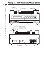
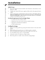
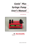
Model ‘11’ - VPF
Syringe Pump
User’s Manual
Model ‘11’ "Virtualy Pulse Free"
Dual Syringe Series
MA1 55-2111
WEEE/RoHS Compliance Statement
EU Directives WEEE and RoHS
To Our Valued Customers:
We are committed to being a good corporate citizen. As part of that commitment,
we strive to maintain an environmentally conscious manufacturing operation. The
European Union (EU) has enacted two Directives, the first on product recycling
(Waste Electrical and Electronic Equipment, WEEE) and the second limiting the use
of certain substances (Restriction on the use of Hazardous Substances, RoHS).
Over time, these Directives will be implemented in the national laws of each EU
Member State.
Once the final national regulations have been put into place, recycling will be offered
for our products which are within the scope of the WEEE Directive. Products falling
under the scope of the WEEE Directive available for sale after August 13, 2005 will
be identified with a “wheelie bin” symbol.
Two Categories of products covered by the WEEE Directive are currently exempt
from the RoHS Directive – Category 8, medical devices (with the exception of
implanted or infected products) and Category 9, monitoring and control instruments.
Most of our products fall into either Category 8 or 9 and are currently exempt from
the RoHS Directive. We will continue to monitor the application of the RoHS
Directive to its products and will comply with any changes as they apply.
• Do Not Dispose Product with Municipal Waste
• Special Collection/Disposal Required
Table of Contents
H a r v a r d A p p a r a t u s P u m p '11' V P F S y r i n g e P u m p
1
SUBJECT
PAGE NO.
General Information ..............................................2
General Safety Summary ...................................3-4
Introduction:
Theory of Operation............................................5
Features..............................................................5
Pump 11 VPF, Front and Rear Views....................6
Installation:
Initial Setup & Location Requirments ................7
Loading the Syringe............................................7
Operation:
Getting Started:
Turn Pump ON ................................................8
Function Keys and Run Indicator ....................8
Entering Syringe Size ......................................9
Entering Flow Rate Range................................9
Entering Flow Rate ..........................................9
Press Run ........................................................9
Check Syringe..................................................9
Advanced Features:
Volume Mode ................................................10
Power Failure ................................................10
Changing Rates ............................................11
Maintenance ..................................................11
Protecting Small, Fragile Syringes ..................11
Appendices:
A. Specifications ..............................................12
B. Table of Popular Syringe Diameters ............13
C. Flow Rates ..................................................14
General Information
H a r v a r d A p p a r a t u s P u m p '11' V P F S y r i n g e P u m p
2
Serial Number
All inquires concerning our product should refer to the serial number of the unit.
Serial numbers are located on the rear of the chassis.
Calibration
All syringe pumps are designed and manufactured to meet their performance specifications at all rated voltages and frequencies. A calibration certificate is available
upon request. Contact customer service for details and pricing.
Warranty
Harvard Apparatus warranties this instrument for a period of two years from date
of purchase. At its option, Harvard Apparatus will repair or replace the unit if it is
found to be defective as to workmanship or material.
This warranty does not extend to damage resulting from misuse, neglect or abuse,
normal wear and tear, or accident.
This warranty extends only to the original customer purchaser.
IN NO EVENT SHALL HARVARD APPARATUS BE LIABLE FOR INCIDENTAL OR CONSEQUENTIAL DAMAGES. Some states do not allow exclusion or limitation of incidental or consequential damages so the above limitation or
exclusion may not apply to you. THERE ARE NO IMPLIED WARRANTIES OF
MERCHANTABILITY, OR FITNESS FOR A PARTICULAR USE, OR OF
ANY OTHER NATURE. Some states do not allow this limitation on an implied
warranty, so the above limitation may not apply to you.
If a defect arises within the two-year warranty period, promptly contact your local
distributor or Harvard Apparatus, Inc. 84 October Hill Road Holliston,
Massachusetts 01746-1388 using our toll free number 1-800-272-2775 (valid
only in the U.S., outside U.S. call 508-893-8999). Goods will not be accepted for
return unless an RMA (returned materials authorization) number has been issued
by our customer service department. The customer is responsible for shipping
charges. Please allow a reasonable period of time for completion of repairs, replacement and return. If the unit is replaced, the replacement unit is covered only for the
remainder of the original warranty period dating from the purchase of the original
device.
This warranty gives you specific rights, and you may also have other rights which
vary from state to state.
Repair Facilities and Parts
Harvard Apparatus stocks replacement and repair
parts. When ordering, please describe parts as
completely as possible, preferably using our part
numbers. If practical, enclose a sample or drawing.
We offer a complete reconditioning service.
CAUTION
This pump is not registered with the FDA and is not for clinical use on human or
veterinary patients. It is intended for research use only.
General Safety Summary
H a r v a r d A p p a r a t u s P u m p '11' V P F S y r i n g e P u m p
3
Please read the following safety precautions to ensure proper use of your syringe
pump. To avoid potential hazards and product damage, use this product only as
instructed in this manual. If the equipment is used in a manner not specified by the
manufacturer, the protection provided by the equipment may be impaired.
To Prevent Hazard or Injury:
U s e P ro p e r P o w e r S u p p l y
The pump is supplied with an approved power supply and line cord. To maintain
the safety integrity of the device, use only one of the following power supplies:
Ault Inc.
Part No.:
Output:
Input:
PW118KA1203
12 Vdc, 1.5 A, 18 W
100-250 Vac, 47-63 Hz, .5A @ 90 Vac Max
Cui Stack
Part No.:
Ouptut:
Input:
DTS120200U/AC1-P6
12 Vdc, 2.0 A
90-264 Vac, 47-63 Hz, .8A Max Input
Globtek Inc
Part No.:
Output:
Input:
TR9CE1666LCP-N
Model # GT-4201D-12
12 Vdc, 1.66 A, 20 W
90-264 Vac, 47-63 Hz, 1A Max
U s e P ro p e r L i n e C o rd
Use only the line cord shipped with the product and make sure line cord is certified
for country of use.
G ro u n d t h e P ro d u c t
This product is grounded through the return path of the DC power supply.To avoid
electric shock, use only approved power supply and line cord with the product.
M a k e P ro p e r C o n n e c t i o n s
Make sure all connections are made properly and securely.
O b s e r v e a l l Te r m i n a l R a t i n g s
Review the operating manual to learn the ratings on all connections.
General Safety Summary
4
H a r v a r d A p p a r a t u s P u m p '11' V P F S y r i n g e P u m p
A v o i d E x p o s e d C i rc u i t r y
Do not touch any electronic circuitry inside of the product.
D o N o t O p e r a t e w i t h S u s p e c t e d F a i l u re s
If damage is suspected on or to the product do not operate the product. Contact qualified service personnel to perform inspection.
O b s e r v e a l l Wa r n i n g L a b e l s o n P ro d u c t
Read all labels on product to ensure proper usage.
CAUTION
Refer to Manual
Functional Ground
Terminal
E n v i ro m e n t a l C o n d i t i o n s
Indoor use only
Temperature 4˚C to 40˚C (40˚F to 104˚F)
Humidity 20% to 80% RH
Well Ventilated Room
Altitude up to 2000 m
Mains Voltage Fluctuation not to Exceed +/- 10% of Nominal
Pump is Rated Pollution Degree 1 in Accordance with IEC 664
Introduction
5
H a r v a r d A p p a r a t u s P u m p '11' V P F S y r i n g e P u m p
Theory of Operation:
The Pump '11' VPF is designed as a low cost infusion pump capable of low to moderate back pressures.
The pump can hold two syringes of any make from 0.5 µl to 10ml. The diameter
of the syringes is entered via the keypad and the internal microprocessor drives a
precision stepper motor to produce accurate fluid flow.
Non-volatile memory stores the last syringe diameter and flow rate along with other
configuration data.
The “Power Failure Mode” can be set to either turn the pump off in the event of
power failure or to resume pumping when power resumes.
Features:
Bright Display and Easy-To-Use Interface
A new, two-line 16 character vacuum fluoressent display along with six membrane
keys make this a most attractive but powerful, easy-to-use syringe pump. Only two
entries required to start pumping; syringe Inside Diameter (mm) and pumping flow
rates. The Flow rate can be changed while the Pump is running.
Two Modes of Operation, Constant Flow Rate and Volume
Dispense
The Pump '11' VPF will operate continuously in RATE mode or accurately dispense a specific amount of fluid in VOLUME mode.
Smooth Flow
Enhanced micro-stepping pump profiles deliver very smooth and consistent flow,
that is virtually pulse free.
Nonvolatile Memory
The pump remembers its last syringe size, flow rate used and configuration settings.
Power Fail Mode
In a power failure the Pump can either RESUME or STOP pumping when power
is returned.
CE Mark Approved
The Pump '11' VPF meets all relevant European EMC and Safety requirements for
laboratory equipment.
Pump '11' VPF Front and Rear Views
H a r v a r d A p p a r a t u s P u m p '11' V P F S y r i n g e P u m p
6
PUSHER
BLOCK
ALLEN
WRENCH
HALF NUT
RUN LED
VPF
KEY PAD
SYRINGE CLAMP
SYRINGE HOLDER
ADJUSTABLE STOP
CAUTION
FOR RESEARCH USE ONLY.
NOT FOR USE ON HUMAN
OR VETERINARY PATIENTS.
POWER
SWITCH
POWER CORD
RECEPTICAL
SERIAL
LABEL
Installation
7
H a r v a r d A p p a r a t u s P u m p '11' V P F S y r i n g e P u m p
Initial Set-up
1.
Read the manual to become familiar with all features and functions of the
Pump '11' VPF.
2.
Connect the external DC power supply and line cord to the pump and main
supply.
3.
Turn on main power switch located on the rear panel. The display will now
illuminate indicating that the power connections are correct. The display will
indicate POWER FAIL. (this is normal as the pump indicates on the display
if power was disrupted since last use.)
Location Requirements for the Syringe Pump
• A sturdy, level, clean and dry surface
• Minimum of one inch (2cm) clearance around the pump
• Appropriate environmental conditions
• A well ventilated room
Loading the Syringe
1.
Release the syringe pusher by pressing the bronze button on the side of the
pusher.
2.
While holding the bronze button ‘in’, slide the pusher to the left.
3.
Raise the spring loaded syringe retainer and swing it out of the way.
4.
Lay the loaded syringe in the ‘V’ shaped holder.
5.
Swing the retainer so it holds the syringe in place.
6.
Move the pusher so it makes contact with the syringe plunger.
Operation: Getting Started
8
H a r v a r d A p p a r a t u s P u m p '11' V P F S y r i n g e P u m p
Getting started
1. Turn Pump ‘ON’
Turn on power using the switch on rear of the pump, the display will light,
and indicate POWER FAIL. (this is normal as the pump indicates on the display if power was disrupted since last use.)
2. Function Keys and Run Indicator
Refer to the colored keypad at the front of the pump to identify the following
functions starting from the right.
RUN/STOP – This turns the pump motor on and off.
ENTER – This key enters the data that is on the display into the memory of
the pump. Also used to query the flow rate.
DIAM – Used to enter or query the syringe diameter.
SET – This key is used to select which digit of the display is to be changed, to
move the decimal point and to move between modes. Each time the set key is
pressed the underline cursor below the digit or character on the display moves
one step to the right. It is used in conjunction with the ascending and descending keys. When it the display shows the desired the correct value the set key
will advance right to the next digit.
▲ ▼ – The ascending and descending keys are used to change the numbers
on the display. ▲ Up key makes numbers increase, ▼ Down Key makes
numbers decrease. When the underline cursor is placed below the decimal
point, the ▲ ▼ keys shift the decimal one place up or down.
Run Indicator – When the pump is running, the highly visible, green LED
above the RUN/STOP key will illuminate.
Operation: Getting Started
H a r v a r d A p p a r a t u s P u m p '11' V P F S y r i n g e P u m p
9
3. Enter Syringe Size
Enter the inside diameter (ID) of the syringe you wish to use. Units are in millimeters (mm).
If you do not know your syringe diameter, refer to appendix B for nominal
inside diameters of most popular syringes. For the greatest accuracy or if your
syringe is not listed in appendix B, measure the inside diameter with a vernier
caliper or other precision measuring tool. Record this value for future use.
Press SET followed by the DIAM key. The previously used diameter will
appear on the display. The underline cursor will appear under the left-most
digit or decimal point. The ▲ and ▼ keys are used to scroll to the desired
number and the SET key moves the underline cursor one place to the right.
Once the desired diameter is displayed, press the ENTER key to place this
value into memory.
4. Enter Flow Rate Range
Choose your flow rate units; either microliters or milliliters, per minute or per
hour.
From the initial RATE VOL CONFIG menu, using the ▲ or ▼ key, move
the underline cursor under the CONFIG mode menu prompt. Press the SET
key to enter the CONFIG mode. Press the SET key again to move the underline cursor to the flow rate choices. Choose your flow rate units while in the
SET:UNITS mode by pressing the ▲ or ▼ keys to scroll the four flow rate
choices; ml/min, µl/min, ml/hr, µl/hr. Once the desired flow rate units are displayed, press the ENTER key to return to the main SET:CONFIG mode.
Press SET or ENTER again to put your desired flow rate units into memory
and return to the RATE VOL CONFIG menu.
5. Enter Flow Rate
From the initial RATE VOL CONFIG menu, press the SET key to enter the
SET:RATE mode. Each time you change the syringe diameter, the previously
used flow rate is erased. If the syringe diameter is unchanged, the previously
used flow rate will appear on the display. The underline cursor will appear
under the left-most digit or decimal point. The ▲ and ▼ keys are used to
scroll to the desired number and the SET key moves the underline cursor one
place to the right. Once the desired rate is displayed, press the ENTER key to
place this value into memory.
6. Press RUN
Press the RUN/STOP key to start pump and begin pumping. The Run
Indicator (Green LED above the RUN/STOP key) will light when the pump
is on and pumping.
7. Check Syringe Often
The Pump 11 VPF will not shut itself off when the syringe is empty or is otherwise overloaded. Although this presents no hazard to the user or the pump,
it is prudent to check the syringe from time to time.
Operation: Advanced Features
H a r v a r d A p p a r a t u s P u m p '11' V P F S y r i n g e P u m p
10
1. Volume Mode
The Pump 11 VPF can be set to dispense a precise volume and then stop. To
activate the volume dispense mode a target volume must be set.
To set a target volume, at the RATE VOL CONFIG display, move the underline cursor, using the ▲ or ▼ key, to VOL. Press the SET key to enter the
VOL set mode. Use the ▲ or ▼ key and the SET key to display a target volume from 00.01 to 99.99. Volume units are either ml (milliliters) or µl
(microliters). Target volume units are established in the CONFIG
SET:UNITS mode; example: if your pumping units are ml/ min or ml/ hr,
then the volume dispense units will be ml’s. Press the ENTER key to select
the desired target volume. Exit the VOL mode by pressing the ENTER key.
Once you press the RUN key, the pump will run until the target volume is
delivered. The display will show the actual volume dispensed along with the
target volume. Press the RUN key each time you want to repeat the volume
dispense. If you press the STOP key during a volume dispense, you can restart
the pump at the place you stopped by pressing the RUN key again.
To exit the volume dispense mode, set the target volume to 00.00 or turn off
and on the pump via the main power switch. NOTE: In the event of a power
failure, the actual dispensed volume and the target volume are not retained in
memory. This means that while in volume dispense mode, if a power failure
occurred, the pump would not resume volume dispense pumping even if the
POWER ON mode was set to run.
2. Power Failure
In the event of a momentary or prolonged power failure, the Pump 11 VPF
can be set to either;
a) Resume pumping when power is returned, with “POWER FAIL” on the
display.
b) Not start pumping when power is returned, with “POWER FAIL” on the
display.
To set the power fail mode, at the RATE VOL CONFIG display, move the
underline cursor, using the ▲ or ▼ key, to CONFIG. Press the SET key to
enter the CONFIG mode options. Use the ▲ or ▼ key to scroll the CONFIG options until you reach the SET:POWER ON: display. Press the SET
key again moving the underline cursor to the right. Use the ▲ or ▼ key to
scroll the POWER:ON choices; ‘stop’ or ‘run’. Press the ENTER key to select
either mode. Exit the CONFIG mode by pressing the ENTER key again and
save the POWER:ON setting in memory.
Operation: Advanced Features
H a r v a r d A p p a r a t u s P u m p '11' V P F S y r i n g e P u m p
11
3. Display Intensity
For varying light conditions, four levels of intensity can be set on the vacuum
fluorescent display
To set the desired display intensity, at the RATE VOL CONFIG display, move
the underline cursor, using the ▲ or ▼ key, to CONFIG. Press the SET key
to enter the CONFIG mode options. Use the ▲ or ▼ key to scroll the CONFIG options until you reach the SET:INTENSITY:. Press the SET key again
moving the underline cursor to the right. Use the ▲ or ▼ key to scroll the
SET : INTENSITY choices; "1", "2", "3", "4" ( 4 is highest intensity, 1 is the
lowest intensity). Press the ENTER key to select the desired display intensity.
Exit the CONFIG mode by pressing the ENTER key again and save the
INTENSITY setting in memory.
4. Changing Rates
If the pump is running at an existing rate it will continue to do so until a new
rate is entered. Except for volume mode, the flow rate can be changed while
the pump is running. As soon as the ENTER key is pressed the pump will
change to the new flow rate. To change rates from the keypad, while in volume mode, the pump must be stopped first.
5. Maintenance
Keep the pump clean and dry. Avoid liquid spills that may find their way into
the electronics.
A small container of grease is provided for periodic lubrication of the lead
screw and guide rods. It is important to keep these guide rods clean and lubricated.
To clean the exterior surfaces, use a lint-free cloth to remove loose dust. Use
care to avoid scratching the display window. For more efficient cleaning, use a
soft cloth dampened with water or an aqueous solution of 75% isopropyl alcohol.
If the pump does not work properly, contact Harvard Apparatus for appropriate instructions.
6. Protecting Small, Fragile Syringes
The Pump 11 VPF will hold microliter size syringes down to 0.5µl size. These
small syringes have fine wire plungers that may be damaged if allowed to bottom out. The pump is equipped with an adjustable stop collar on one of the
guide rods. Use the provided hex wrench to position and lock the stop collar
to prevent damage to small syringes.
Appendix A
H a r v a r d A p p a r a t u s P u m p '11' V P F S y r i n g e P u m p
12
Pump '11' VPF Specifications
Type
Microprocessor single syringe, infusion only
Syringe/Size for Pump '11' VPF
with Holder For:
Plastic or glass
2 Syringe
From 0.5 µ l to 10 ml
Flow Rate Range:
Minimum / Maximum
0.077 nl/hr with 0.5 µ l syringe / 0.4393 ml/min with 10cc
syringe
Calibration
Automatic, enter syringe size up to 35 mm Inside Diameter
Display
2 line, 16 character vacuum fluorescent display and green
run led
Nonvolatile Memory
Stores diameter, rate and configuration settings
Maximum Force
(25 lb.) *
Maximum Pressure
100 p.s.i. with 10cc syringe; 175 p.s.i. with 1 ml syringe
Drive Motor
1.8° step angle geared 36:1 motor
Step Rate:
Minimum / Maximum
Pusher Advance/Step
1 pulse in 27.6 sec / 200 steps/sec
0.0444 µ m pusher advance per motor step
Pusher Travel Rate:
Minimum / Maximum
0.0388 µ m/min / 0.8333 mm/min
Dynamic Range
1 to 16,384
Leakage to Ground
Typically < 150 µ A
Ground Resistance
Typically < 0.05 ohms
Input Power
12 VDC 1.5Amps
Input Power Connection
2.5mm ID x 5.5mm OD male plug
Power Supply
100/250 VAC, 50/60 Hz, 18 Watts Universal Power
Supply, Use Only a Harvard Apparatus Approved Power
Supply and Line Cord
Size, H x W x D
11.4 x 22.9 x 11.4 cm (4-1/2 x 9 x 4-1/2 in)
Weight
2.3 kg (5 lb)
* Actual force is higher, but not recommended for applications requiring more than
25lbs of force.
Appendix B: Syringe Inside Diameter
H a r v a r d A p p a r a t u s P u m p '11' V P F S y r i n g e P u m p
13
–––––––––––––––––––
Terumo
Size
Diameter
3 cc
8.95 mm
5
13.00
10
15.80
1 cc
4.78 mm
–––––––––––––––––––
Sherwood–Monoject
Plastic
Size
Diameter
1 cc
4.65 mm
3
8.94
6
12.70
12
15.90
–––––––––––––––––––
Popper & Sons, Inc.
“Perfektum” Glass
Size
Diameter
0.25 cc 3.45 mm
0.5
3.45
1
4.50
2
8.92
3
8.99
5
11.70
10
14.70
–––––––––––––––––
Stainless Steel
Size
Diameter
8 cc
9.525 mm
–––––––––––––––––––
Becton Dickinson
Plastic “Plasticpak”
Size
Diameter
1 cc
4.78 mm
3
8.66
5
12.06
10
14.50
–––––––––––––––––––
Air–Tite “All Plastic”
Size
Diameter
2.5 cc 9.60 mm
5.0
12.45
10
15.90
–––––––––––––––––––
Unimetrics
Series 4000 & 5000
Size
Diameter
10 µl
0.460 mm
25
0.729
50
1.031
100
1.460
250
2.300
500
3.260
1000
4.610
–––––––––––––––––––
SGE
Scientific Glass
Engineering
Size
Diameter
25 µl
0.73 mm
50
1.03
100
1.46
250
2.30
500
3.26
1.0 ml 4.61 mm
2.5
7.28
5
10.30
10
14.57
–––––––––––––––––––
Hamilton–Microliter
Series Gastight
Diameter
Size
.5 µl
0.103
mm
1
0.1457
2
0.206
5
0.3257
10
0.460
25
0.729
50
1.031
100
1.46
250
2.3
500
3.26
1.0 ml 4.61 mm
2.5
7.28
5
10.3
10
14.57
Appendix C: Flow Rates
H a r v a r d A p p a r a t u s P u m p '11' V P F S y r i n g e P u m p
14
µl/hr
nominal
syringe
size
nominal
diameter
(mm)
Min
0.10
0.0001
1 µl
0.15
2 µl
min
max
µl/min
ml/hr
min
max
min
max
1.241
0.0001
0.0207
0.0001
0.0012
0.0002
2.793
0.0001
0.0465
0.0001
0.0027
0.21
0.0004
5.476
0.0001
0.0912
0.0001
0.0054
5 µl
0.33
0.0009
13.52
0.0001
0.2253
0.0001
10 µ l
0.46
0.0016
26.27
0.0001
0.4379
25 µ l
0.73
0.0040
66.16
0.0001
50 µ l
1.03
0.0080
131.7
100 µ l
1.46
0.0161
250 µ l
2.30
ml/min
min
max
0.0135
0.0001
0.0002
0.0001
0.0262
0.0001
0.0004
1.102
0.0001
0.0661
0.0001
0.0011
0.0002
2.195
0.0001
0.1317
0.0001
0.0021
264.7
0.0003
4.411
0.0001
0.2647
0.0001
0.0044
0.0401
656.6
0.0007
10.94
0.0001
0.6566
0.0001
0.0109
1,000 µ l 3.260
0.0806
1319.0
0.0014
21.98
0.0001
1.319
0.0001
0.0219
1 ml
4.61
0.1611
2,638
0.0027
43.98
0.0001
2.638
0.0001
0.0440
2.5 ml
7.28
0.4017
6,577
0.0067
109.6
0.0004
6.577
0.0001
0.1096
3 ml
8.66
0.5688
9,311
0.0094
155.2
0.0006
9.311
0.0001
0.1552
5 ml
10.30
0.8055
9,999
0.0134
219.5
0.0008
13.17
0.0001
0.2195
10 ml
14.57
1.610
9,999
0.0268
439.3
0.0016
26.36
0.0001
0.4393
Max
35.00
9.289
9,999
0.1547
2,535.0
0.0092
152.1
0.0002
2.535