1
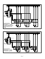
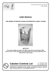
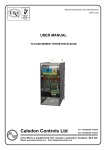
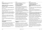
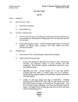
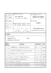
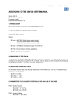
Caledon Controls Ltd
Tel +44 (0)1555 773355
Fax +44 (0)1555 772212
Unit 2 Block 4, Castlehill Ind. Est., Carluke, Lanarkshire, Scotland, ML8 5UF
Website www.caledoncontrols.co.uk
Email [email protected]
Data Sheet and User Manual
CU02: Staging Controller for Load Sequencing Control
Up to 6 Stages in one unit
Up to 16 stages with slave units*
Directly interfaces to low cost
logic input thyristors or to
contactors
Built in Burst fire or Single Cycle
Control Algorithms
Separate analogue output may be
used with phase angle thyristors
Allows modulating stage
oversizing for stable control
Stage rotation facility to balance
heater usage
*Check availability
Application
The staging controller is designed for use with a large process heating system which is split into several banks of heaters, all
of which apply heat input to the same heating load. The staging controller balances the required heating demand by switching
on the number of stages (heater banks) which most nearly match the demand, and modulating one additional stage to make
up the difference. Versions are available with combined relay + logic outputs and all logic outputs. A single analogue output is
also provided. Relay + logic types are used with contactor stages + 1 modulating thyristor stage; all logic outputs are used
when all the stages are controlled by thyristors. The analogue output may be used to drive one modulating thyristor which
accepts a standard analogue input signal if preferred.
The staging technique provides the following advantages:1
On large electric heating systems the load is broken into banks of a smaller kilowatt rating, and the maximum size of
load being switched on or off at any one time is reduced. This reduces the magnitude of switching disturbances on
supply lines, and is particularly useful where the load represents a significant proportion of the supply capacity.
2
On systems where the load demand does not frequently vary over a wide range the non-modulating stages may be
contactor controlled, and the modulating stage thyristor controlled.
Brief Description
The Caledon staging controller accepts an analogue input signal from a temperature controller which represents heating
demand. A second input is provided for use with a manual potentiometer. The controller provides outputs for 6 stages of
heating and there is provision for future slaving of additional units to increase the number of stages to a maximum of 16. The
stages may be either 5 relay outputs for use with contactors and 1 logic / analogue output for a modulating thyristor, or 6 logic
outputs for use with thyristors. Modulating logic outputs operate in either burst fire mode, or single cycle burst fire mode. Both
are intended for use with thyristor controllers which accept a logic input signal and have zero voltage switch on. The stages
may either be of the same power rating, or the modulating stage may be oversized which potentially reduces the amount of
stage switching required to maintain temperature control . A single 0-5V analogue output is provided which may be used with
an analogue input thyristor stack for the modulating stage if preferred - this allows a phase angle stack to be used for
example. In the case of logic input thyristor only systems in which all the stages have the same power rating, the stages may
optionally be rotated around the heater banks, which helps to balance the total usage of each heater bank.
Specifications
Supply voltage
Power consumption
Ambient temperature
Approximate Dimensions
Input signal
115V or 230V AC 50 / 60 Hz +10% -15%
4VA
0-50OC
104mm high x 155mm wide x 80mm deep (Symmetrical DIN rail mounted)
0-5V, 0-10V, 1-5V, 2-10V, 0-20mA, 4-20mA, link selectable
Auxiliary input signal
Output signal
0-5V (manual input) may be fed by a 10kΩ potentiometer powered from the unit
Non modulating stages: relay or logic signal (specified at time of ordering)
Modulating stage: Logic signal for use with zero voltage switch on thyristors, 1 off
analogue signal (0-5V). Relay contacts rated 250V AC, 2A
Contact closure or npn pull down switches unit to manual operation
LED indicators for power, manual operation selected, outputs on
Complies with European Low Voltage Directive and major international standards
Pollution degree 2, Overvoltage category 3, IEC 664
Complies with European EMC Directive for operation in an industrial environment
Digital input signal
Indicators
Safety Standards
EMC Standards
Preset Potentiometers
P1
Stage switching time delay
P2
Ramp time
In setup mode sets modulating stage oversize
P3
Burst fire cycle time
0.25s to 1 minute (prevents rapid cycling of stages)
5-50s (see section on Ramp Function)
0-100%
0.3s to 20s at 50% duty cycle
Jumper and DIP Switch Options Settings
Jumpers - Analogue Input Selection
Off
On
JMP1 A
0-5V
0-10V
JMP1 B
Voltage Input
Current Input (connects a 250Ω resistor
across the input). Set Jmp 1A off.
For signals with offset (1-5V, 2-10V, 4-20mA) set switch 1:7 on.
DIP
Switch 1
1:1
Function
Notes
Off
Single cycle operation
On
Standard burst fire operation
Select the control mode for the modulating stage
logic output.
Switches 1:2 to 1:4 must be set correctly for the modulating logic output to operate correctly in single cycle mode. The
controller power supply must also be wired correctly to match the setting on switch 1:2. The switches must also be set
correctly for the logic output to operate correctly in burst fire mode, unless switch 1:6 is on, in which case the setting of
these switches, and the power supply connection is immaterial If the analogue output is used for the modulating stage the
setting of these switches, and the power supply connection is immaterial.
1:2:
1:3
1:4
1:5
1:6
1:7
1:8
Off
Controller power supply in phase with line to line
supply
Normal operation
On
Controller power supply in phase with line to neutral
Cannot be used with 2-line control.
Off
Load connection for 2-line control. Load star or delta
connected.
Only 2 of the 3 lines are controlled. The third is
directly connected.
On
Load connection for 3 line control
All 3 lines are controlled by thyristors.
Off
3-line control, 3-wire load connection (star or delta).
On
3-line control, 4-wire star load connection
Only operative if 1:3 is on. Must then match the load
connection.
Off
In auto mode the front panel potentiometer has no
function
On
In auto mode the front panel potentiometer sets an
upper limit on the input control signal
Off
No function
On
Modulating logic output signal not synchronised to
the mains frequency
Off
Analogue inputs without offset (0-5V etc)
On
Analogue inputs with offset (1-5V etc)
Off
Normal operating mode
On
Setup mode
In manual mode the potentiometer controls the
output power independent of the input control signal.
Applies to software versions CU07E5Rx (where x is
the issue number). Standard from 2005.
Software version CU07E1Rx available on request
offers proportioning of the input signal by the front
panel potentiometer when in manual mode.
Normally should be off. See switch 1:2 above and
section on Controller supply and synchronisation
In set up mode potentiometer P2 may be used to set
the oversize of the modulating stage.
See section on Oversizing the modulating stage.
Page 2
DIP
Switch 2
Switches 1 to 4 set the number of stages in addition to the modulating stage. For a single unit (without slaves) 5 is the
maximum valid number.
Switch Setting
1 LSB
0
1
0
1
0
1
0
1
0
1
0
1
0
1
0
1
2
0
0
1
1
0
0
1
1
0
0
1
1
0
0
1
1
3
0
0
0
0
1
1
1
1
0
0
0
0
1
1
1
1
4 MSB
0
0
0
0
0
0
0
0
1
1
1
1
1
1
1
1
Number of
non
modulating
stages
#
1
2
3
4
5
6
7
8
9
10
11
12
13
14
15
# When switches are set to 0000 the modulating stage output is fed to all stages, allowing simultaneous modulating of all
stages without rewiring (Not suitable for use with contactors!)
5
6
7*
8*
Off
No function
On
Stages rotate.
The outputs are rotated round the stages every 5 hours. see section on
Stage rotation. See also appendix 1 on page 8 for different software
versions
Off
Output ramp function off
On
Output ramp function on
Off
Stand alone unit or master
On
Slave Unit
Off
Slave Unit 1 (stages 7-11)
On
Slave Unit 2 (stages 12-16)
When the ramp function is on the modulating output ramps in response to
a step change of input. The time to ramp from 0-100% is set on P 2
Sets whether the unit is a master or a slave. A master unit may be used
alone for 6 stages, or with 1 or 2 slaves for 11 or 16 stages. Slave units do
not have a modulating output.
The setting on this switch only takes effect if switch 2:7 is set on, and
determines how the master unit treats the slave.
* Initial versions of the staging controller do not support slave operation. Set switches 7 and 8 off.
Terminal Function List
Terminal
Number
Function
Notes
1
Functional Earth
Not a safety earth. May be connected to chassis to improve EMC noise immunity.
2
+5V Output
May be used to energise a 10K potentiometer connected to the manual input.
3
Manual Input
Accepts a 0-5V signal when the controller is in manual mode. It is advisable to use a
screened cable for the leads to the manual potentiometer, particularly if they are longer than
1 metre, to avoid interference pick up which could cause jitter when switching between
stages. The screen should be grounded adjacen to the controller, or to terminal 1 if this is
grounded.
4
0V
0V common for input signals, manual potentiometer and analogue output.
5
Setpoint input
Accepts the setpoint signal (power demand) from a temperature controller. Signal type
determined by JMP1 setting.
6
Auto/manual select
When off controller uses the main setpoint input (5). When linked to 0V (or pulled to 0V by
an NPN transistor) controller uses manual input (3)
7
0V
0V common for input signals and analogue output.
8
Analogue output
0-5V signal which represents the output value of the modulating stage.
9
0V
0V common for input signals, analogue output and comms.
10
Comms
For future use, to enable control of slave controllers. Do not wire to these terminals.
11
Comms
12
Auxiliary Output
Not used (provides an additional logic output for special applications, selected by JMP2.
13
+12V
+12V unregulated supply. Common positive for logic output signals.
14
Output 1
Logic output (-ve) pull down NPN open collector output, to drive a thyristor controller. In
systems with contactors, or where the modulating control is not rotated around the heaters,
this stage will be the modulating stage. Outputs 2-6 are either on or off.
15
+12V
+12V unregulated supply. Common positive for logic output signals.
16
Output 2
17
Output 3
18
Output 4
These outputs are specified at the time of ordering as either logic ouputs (NPN open
collector pull down), or N/O relay outputs for driving contactors. Contactor coils should be
suppressed. In systems with less than 6 stages the lower numbered outputs are used; eg a
3 stage system uses outputs 1, 2 and 3.
19
Output 5
20
Output 6
21
Relay Common
Common for outputs 2-6 when these are specified as relay outputs.
22
Supply Live
Either 115V +10% -15%, or 230V +10% -15%, 50 or 60 Hz. Voltage is selected by jumper
assembly at top right of module.
23
No connection
Do not make any connection to this terminal.
24
Supply Neutral
Page 3
Safety and Regulatory Considerations
The controller must be wired in accordance with electrical standards applicable in the country of installation.
When controlling heating loads it is important to consider the effects of loss of control due to a fault; eg the heating power
being turned fully on. If this could result in a dangerous situation then independent means of monitoring the load and
removing power should be fitted. This is a requirement of international standards.
Control of thyristors in single cycle mode gives rise to harmonic currents and electrical noise, and it should be ascertained
that these fall within acceptable limits for the application.
System Configuration Options and Requirements
Two versions of the controller are available, for use with thyristor only systems, and contactor / thyristor systems. Typical
wiring schematics for a 3-stage system of each type are given.
Contactor + Thyristor Control
This is the lowest cost option, and is most suited to loads which do not va ry rapidly, or tend to stabilise at a more or less
constant value for long periods. The controller is fitted with relays to operate the contactors. A single modulating thyristor
stage is used (stage 1 and output 1) to exactly balance the load demand. The thyristor may be either a logic input type,
driven by the stage 1 logic output on the staging controller, or an analogue input type driven by the analogue output on the
controller. It is advantageous if the modulating stage is oversized relative to the contactor stages, as this will help reduce the
frequency of contactor switching, and avoid the situation where the required power demand is met just at the point where one
stage is switching on / off.
All Thyristor Control
This is a more versatile form of control. Only one of the stages is modulating (stage 1, output 1, but see Stage Rotation
below), but the non modulating stages are also switched by thyristors. This is more satisfactory for loads which vary
frequently, as there is not the switching life problem associated with contactors. The thyristors may all be logic input types, or
alternatively the modulating stage may be an analogue input type. It is less important th an when using contactors that the
modulating stage be oversized, as other stages can be switched frequently . However, better control may be obtained if the
modulating stage is oversized, as there will always be time delays associated with the heating and cooling of elements etc as
stages are switched in and out.
Oversizing the Modulating Stage
Most heater batteries are designed with all stages having the same power rating. From a control point of view there is an
advantage in having the modulating stage oversized relative to the other stages. Consider the case where the relative sizes of
the modulating stage and the other stages are 100 : 80. As the input signal rises from zero the modulating stage output will
increase until it is fully on. At this point the second stage is switched in, and the modulating output is cut back to 20%. If t he
input signal now starts to fall, the modulating stage has to fall back by 20% before the second stage is switched back off, and
when this happens the modulating output is stepped up to 80%. It must then be required to increase by 20% before the
second stage is switched back on. It will be seen that the oversizing creates a switching hysteresis which reduces the number
of times stages switch on and off in response to the input control signal. If the stages are of equal size there is, strictly
speaking, no hysteresis. In practice, in this controller a small hysteresis of 1% is introduced. In conjunction with the timed
switching delay function, this results in acceptable switching frequency, but at the expense of a potential loss of control
accuracy.
Setting the Oversize
The controller must be set up to match the oversize of the modulating stage of the heater battery if appli cable. (The default
setting is no oversize). To set up the oversize, switch on DIP switch 1: 8 (Setup). The 0-5V analogue output (terminals 8 and
9) now represents modulating stage oversize 0-100%. which may be monitored on a digital volt meter . For 10 seconds after
switching on the switch the value transmitted is the current saved setting , and if the switch is switched off again within the 10
seconds this value will be retained. After 10 seconds the value transmitted is read from potentiometer P2 and may be
adjusted to the value required (The previous stored value is now lost). When it is set correctly, switch off DIP switch 1:8. The
value is then stored in EEPROM, and the analogue output reverts to its normal function.
Stage Rotation
DIP switch 2:5 enables stage rotation. This rotates which output on the controller is assigned to each stage on a fixed periodic
basis. (Standard period is 5 hours). The purpose is to help balance the usage of all the heater stages in the battery over time.
Stage rotation can only be used, and must only be set when:1
All the heater stages are of the same power rating.
2
All the heater stages are thyristor controlled.
3
The logic outputs are used for all stages.
Modulating Stage Thyristor Firing Modes
The logic output offers two firing modes; burst fire and single cycle burst fire.
Burst fire control is a method of controlling the load power by switching the current on and off. The current is on for a number
of supply cycles and off for a number of cycles. The load power is varied by varying the ratio of on time to off time. In burst fire
mode the fastest cycle time offered by this controller is 0.3s at 50% duty cycle, corresponding to approximately 8 cycles on
and 8 cycles off at 50Hz. Potentiometer P3 may be used to adjust the cycle time between 0.3s and 20s.
Single cycle burst fire control is the fastest type of burst fire control possible. At 50% duty cycle (power) one mains cycle on is
followed by one off. Above 50% power only one mains cycle is allowed to be off before another on cycle. Any number of on
cycles may follow each other consecutively. Below 50% power only one mains cycle is allowed to be on before another off
Page 4
cycle. Any number of off cycles may follow each other consecutively. The average ratio of on to off cycles is controlled to
obtain the required average load power. Single cycle control can be used for fast response loads, or to minimise the effect of
burst fire operation on supply generator speed control.
If phase angle control is preferred for the modulating stage the analogue output (0-5V) may be used to drive a suitable
thyristor stack which accepts an analogue input.
Controller Supply Connection, Mains Synchronisation and Typical Wiring Schemes
The controller must be adjusted for the correct supply voltage; either 115V or 230V +10% -15%. The setting is adjusted by
moving the jumper plug, which is on the right hand side of the unit, to the correct position. To gain access undo the 2 screws
at either end of the unit, remove the cheeks and unclip the cover. 115V is set with the plug moved toward the top of the unit,
and 230V with the plug moved toward the bottom of the unit, as indicated by the small lines on the PCB which should be
alongside the wire links in the plug.
Typical wiring schematics are given at the end of the manual for 3-stage 3-phase systems.
The controller logic output for the modulating stage is synchronised to the mains frequency. This synchronisation is derived
via the controller power supply.
When operating with single cycle control it is essential that the power supply be correctly phase related to the supply which
feeds power to the heaters. The thyristors must have zero voltage switch on.
If the thyristors have 3-line control (the ones i n the typical schematics have only 2-line control) the controller power supply
may be derived across two of the lines via a step-down transformer (as shown in the schematics) or connected line to
neutral. DIP switch 1:2 must be set to match.
If the thyristors have only 2-line control the power supply must be derived across the two lines which are controlled by the
thyristor as shown in the schematics. This is to avoid the need to know the supply rotation.
With this proviso the supply rotation is immaterial in all cases.
DIP switches 1:3 and 1:4 must be set to match the load configuration.
When operating with burst fire control, DIP switch 1:6 may be switched on, which unsynchronises the logic output from the
mains cycles. The phase relationship of the controller power supply to the load power supply is then immaterial and the
setting of DIP switches 1:2 to 1:4 will have little effect. It may be beneficial to use synchronous operation, particularly with fast
cycle rates, as the synchronous algorithm used is designed to maintain load balance and eliminate small DC components
from the load current. If the supply to the controller is phased correctly it allows the flexibility to change to single cycle
operation if found desirable. If synchronous operation is chosen then the power supply connection and DIP switch settings
must be adhered to as for single cycle operation.
Delay between Stage Switching
Each time a stage switches either on or off a timer is set, which prevents further stage switching until it times out. The timer is
adjustable by potentiometer P1 between 0.25s and 1 minute. The timer prevents rapid cycling of the stages, and ensures that
on initial switch on, when the input control signal to the controller may be at maximum, the load is switched on in stages in a
controlled manner. It also inevitably means that the load cannot be switched off suddenly by reducing the control signal to
zero, and if this is a requirement (eg in emergency) some other means must be provided for cutting the load power.
The timer should not be set longer than necessary, as this may have an adverse effect on control stability. The longer the time
set, the longer the integral time constant in a PID temperature controller will have to be.
Ramp Function
DIP switch 2:6 switches on this function. When it is enabled the modulating stage is restrained from making step changes in
its output. It responds to a step change in input demand in either direction by ramping its output, at a rate set on
potentiometer P2. As it is the modulating stage reaching either zero or full output which triggers stage switching, this function
may be used in addition to, or instead of, the stage switc hing delay to control the rate at which load power can be increased or
decreased. P3 adjusts the time taken for the controller, given a step change from 0-100% in input signal, to switch on all
stages (independent of the number of stages), ramping the modulating stage after each time another stage switches in. The
time is adjustable from 5s to 50s.
Auto / Manual Function
This function enables an optional manual potentiometer to be connected as shown in the typical schematics. Control by the
potentiometer is selected by linking terminals 6 and 7.
When control is by the manual potentiometer DIP switch 1:5 determines whether the potentiometer controls the power
independent of the main control signal, or whether it proportions the main control signal. In the latter case the main (auto)
control signal will have to be present to obtain any output in manual, and the potentiometer will proportion the output over the
range zero to the value of the main auto control signal.
Slave Units
Slave operation is not yet available, but when introduced will enable operation with a master unit and up to two slaves,
allowing up to 16 stages to be controlled. Each slave unit will have 5 non modulating stages, which are switched on and off
under control of the master unit. Because the modulating output is confined to the master unit, stage rotation cannot be
performed across slave units, and is constrained to a maximum of six stages.
Page 5
Page 6
Line3
Line2
Line1
Control
Transforme r
AUTO / MANUAL
L
10K
+
N
COM
21
7
OP6
20
OP5
19
2
OP4
18
3
OP3
17
4
OP2
16
+12V
15
OP1
14
+12V
13
5
ANALOGUE
CONTROL
SIGNAL
FROM
TEMPERATURE
CONTROLLER
7
INPUT
SIGNAL
OP1 LOGIC
OTHERS RELAY
Staging
Controller
CONTACTOR
CONTACTOR
STAGE 1 ( MODULATING)
Loa d2
Loa d1
L oad 3
Loa d2
L oad 3
L oad 3
Loa d1
Typical wiring
schematic, 3 - stage
contactor system with
modulating thyristor
stage.
Loa d2
+
LOG IC
SIGNAL
THYRISTOR
Loa d1
MANUAL
POT
6
STAGE 2
STAGE 3
Li ne3
Li ne2
Li ne1
OP6
20
7
OP5
19
OP4
18
2
OP3
17
3
OP2
16
4
+12V
15
OP1
14
+12V
13
Staging
Controller
STAGE 1
STAGE 2
Page 7
L oad2
L oad1
+
L OGIC
SIGNAL
THYRISTOR
L oad3
L oad2
+
L oad1
Typical wiring
schematic, 3 - stage
all thyristor system
THYRISTOR
L oad3
+
L OGIC
SIGNAL
THYRISTOR
L oad2
7
L oad1
5
ALL OUTPUTS
LOGIC TYPE
L oad3
ANALOGUE
CONTROL
SIGNAL
FROM
TEMPERATURE
CONTROLLER
N
L OGIC
SIGNAL
+
L
6
INPUT
SIGNAL
MANUAL
POT
24
AUTO / MANUAL
22
Control
Transforme r
STAGE 3
Appendix 1
A number of different software versions have been made available for this instrument. The resulting instruments have been
assigned part numbers as follows:-
For Logic Output Types (All thyristor control)
CU02-Logic
CU02-Logic-CU07E5
The standard instrument, which operates as described in this document.
CU02-Logic-CU07E8
Fast Rotating Stages
When DIP switch 2:5 is switched on the function of the outputs is rotated every 2 seconds.
For example consider a 6 stage system. The signal level mi ght be set so that 2 stages are
required to be on and the modulating stage is required to be at 50% power. In the standard
instrument Output 1 would be modulating, outputs 2 and 3 would be on, and outputs 4, 5
and 6 would be off. In this instrument, after 2 seconds output 1 would be off, output 2 would
be modulating, outputs 3 and 4 would be on and outputs 5 and 6 would be off. After a
further 2 seconds Outputs 1 and 2 would be off, output 3 would be modulating, outputs 4
and 5 would be on and output 6 would be off, etc. This operation is only suitable for use
with single cycle control, and if heaters are distributed around a vessel ensures that the
heat input is evenly distributed.
CU02-Logic-CU07E9
Sequential Modulating Stage
When DIP switch 2:5 is switched on, the modulating output progresses as the demand
increases. For example consider a system with 4 equal stages. Up to 25% demand only
output 1 is on and modulating. Between 25% and 50% power output 1 is full on and output
2 is modulating. Between 50% and 75% power outputs 1 and 2 are full on and output 3 is
modulating. Between 75% and 100% power outputs 1 - 3 are full on and output 4 is
modulating. This mode only operates with equal stages, and there is no hysteresis
between stages. The switching delay time and ramp function operate as standard.
For Relay Output Types (Thyristor + contactor control)
CU02-Relay
CU02-Relay-CU07E5
The standard instrument which operates as described in this document.
No other variants have currently been made for thyristor + contactor control.
Cu10L1r7
Page 8