1
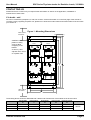
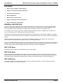
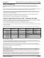
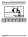
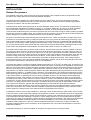
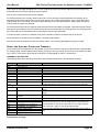
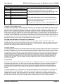
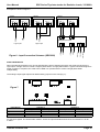
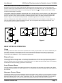
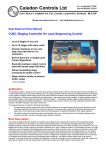
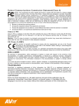
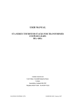
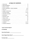
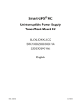
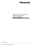
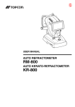
Manual Issue Number R4, Date; May 2004
p034L1r4pdf.lwp
USER MANUAL
SRC SERIES THYRISTOR STACKS FOR RESISTIVE LOADS, 315-800A
IMPORTANT
This manual applies to stacks in the SRC range which are rated above 300A.
Units of lower current rating may have different terminal number assignments from
those shown in this manual
Caledon Controls Ltd
Tel +44 (0)1555 773355
Fax +44 (0)1555 772212
Unit 2 Block 4, Castlehill Ind. Est., Carluke, Lanarkshire, Scotland, ML8 5UF
Website www.caledoncontrols.co.uk Email [email protected]
User Manual
SRC Series Thyristor stacks for Resistive Loads, 315-800A
REVISION HISTORY
R1
R2
R3
R4
First issue April 2001
September 2002
Corrects errors in the fuse type table for 600A and 800A units. Adds
improved instructions for removal and replacement of end contact fuse
types
November 2003
May 2004
Details of new driver card shelf. Updated dimensional drawing
Corrected error in terminal function list; table page 13, B1, B2, B3
incorrectly assigned.
Caledon Controls Ltd.
Page 2
User Manual
SRC Series Thyristor stacks for Resistive Loads, 315-800A
Table of Contents
REVISION HISTORY . . . . . . . . . . . . . . . . . . . . . . . . . . . . . . . . . . . . . . . . . . . . . . . . . . . . . . . . . . . Page 2
CONTACTING US . . . . . . . . . . . . . . . . . . . . . . . . . . . . . . . . . . . . . . . . . . . . . . . . . . . . . . . . . . . . . . Page 4
FEATURES . . . . . . . . . . . . . . . . . . . . . . . . . . . . . . . . . . . . . . . . . . . . . . . . . . . . . . . . . . . . . . . . . . . . Page 5
GENERAL DESCRIPTION . . . . . . . . . . . . . . . . . . . . . . . . . . . . . . . . . . . . . . . . . . . . . . . . . . . . . . Page 5
SRC 1000 Series . . . . . . . . . . . . . . . . . . . . . . . . . . . . . . . . . . . . . . . . . . . . . . . . . . . . . . . . . . Page 5
SRC 2000 Series . . . . . . . . . . . . . . . . . . . . . . . . . . . . . . . . . . . . . . . . . . . . . . . . . . . . . . . . . . Page 5
SRC 3000 Series . . . . . . . . . . . . . . . . . . . . . . . . . . . . . . . . . . . . . . . . . . . . . . . . . . . . . . . . . . Page 5
Current Ratings and Approximate
Dimensions (height x width x depth) . . . . . . . . . . . . . . . . . . . . . . . . . . . . . . . . . . . . . . . . . Page 6
ORDERING INFORMATION . . . . . . . . . . . . . . . . . . . . . . . . . . . . . . . . . . . . . . . . . . . . . . . . . . . . . Page 6
SPECIFICATIONS . . . . . . . . . . . . . . . . . . . . . . . . . . . . . . . . . . . . . . . . . . . . . . . . . . . . . . . . . . . . . Page 6
Physical . . . . . . . . . . . . . . . . . . . . . . . . . . . . . . . . . . . . . . . . . . . . . . . . . . . . . . . . . . . . . . . . . . Page 6
Environmental . . . . . . . . . . . . . . . . . . . . . . . . . . . . . . . . . . . . . . . . . . . . . . . . . . . . . . . . . . . . . Page 6
Electrical . . . . . . . . . . . . . . . . . . . . . . . . . . . . . . . . . . . . . . . . . . . . . . . . . . . . . . . . . . . . . . . . . Page 6
Control Signal Inputs and Outputs . . . . . . . . . . . . . . . . . . . . . . . . . . . . . . . . . . . . . . . . . . . Page 7
Analogue input card . . . . . . . . . . . . . . . . . . . . . . . . . . . . . . . . . . . . . . . . . . . . . . . . . . . Page 7
LED Indicators . . . . . . . . . . . . . . . . . . . . . . . . . . . . . . . . . . . . . . . . . . . . . . . . . . . . . . . Page 7
Compliance with Standards . . . . . . . . . . . . . . . . . . . . . . . . . . . . . . . . . . . . . . . . . . . . . . . . . Page 7
European Low Voltage Directive . . . . . . . . . . . . . . . . . . . . . . . . . . . . . . . . . . . . . . . . Page 7
Electromagnetic Compatibility . . . . . . . . . . . . . . . . . . . . . . . . . . . . . . . . . . . . . . . . . . Page 7
SAFETY INFORMATION . . . . . . . . . . . . . . . . . . . . . . . . . . . . . . . . . . . . . . . . . . . . . . . . . . . . . . . . Page 8
TABLE OF SEMICONDUCTOR FUSE TYPES
– CHANGING THE FUSES . . . . . . . . . . . . . . . . . . . . . . . . . . . . . . . . . . . . . . . . . . . . . . . . . . . . . . Page 8
Blade Contact Types . . . . . . . . . . . . . . . . . . . . . . . . . . . . . . . . . . . . . . . . . . . . . . . . . . . . . . . Page 8
End Contact Types . . . . . . . . . . . . . . . . . . . . . . . . . . . . . . . . . . . . . . . . . . . . . . . . . . . . . . . . Page 8
INSTALLATION . . . . . . . . . . . . . . . . . . . . . . . . . . . . . . . . . . . . . . . . . . . . . . . . . . . . . . . . . . . . . . . Page 10
General Requirements . . . . . . . . . . . . . . . . . . . . . . . . . . . . . . . . . . . . . . . . . . . . . . . . . . . . Page 10
Mounting . . . . . . . . . . . . . . . . . . . . . . . . . . . . . . . . . . . . . . . . . . . . . . . . . . . . . . . . . . . . . . . . Page 11
Cover Removal and Replacement . . . . . . . . . . . . . . . . . . . . . . . . . . . . . . . . . . . . . . . . . . Page 11
Typical Wiring Schematics . . . . . . . . . . . . . . . . . . . . . . . . . . . . . . . . . . . . . . . . . . . . . . . . . Page 12
Recommended Power Cable Sizes . . . . . . . . . . . . . . . . . . . . . . . . . . . . . . . . . . . . . . . . . Page 13
Power Cables and Access to the Load
Terminals . . . . . . . . . . . . . . . . . . . . . . . . . . . . . . . . . . . . . . . . . . . . . . . . . . . . . . . . . . . . . . . . Page 13
Signal and Auxiliary Connection Terminals . . . . . . . . . . . . . . . . . . . . . . . . . . . . . . . . . . . Page 14
Terminal Function List . . . . . . . . . . . . . . . . . . . . . . . . . . . . . . . . . . . . . . . . . . . . . . . . Page 14
Auxiliary Line Connections . . . . . . . . . . . . . . . . . . . . . . . . . . . . . . . . . . . . . . . . . . . . Page 15
Fan and Analogue Input Card
Supply Connection . . . . . . . . . . . . . . . . . . . . . . . . . . . . . . . . . . . . . . . . . . . . . . . . . . . Page 15
Control Cables . . . . . . . . . . . . . . . . . . . . . . . . . . . . . . . . . . . . . . . . . . . . . . . . . . . . . . Page 15
Logic Inputs . . . . . . . . . . . . . . . . . . . . . . . . . . . . . . . . . . . . . . . . . . . . . . . . . . . . . . . . . Page 15
Analogue Inputs . . . . . . . . . . . . . . . . . . . . . . . . . . . . . . . . . . . . . . . . . . . . . . . . . . . . . Page 16
Fuse Failure Indication and Output
Signal . . . . . . . . . . . . . . . . . . . . . . . . . . . . . . . . . . . . . . . . . . . . . . . . . . . . . . . . . . . . . . Page 17
BRIEF NOTES ON OPERATION . . . . . . . . . . . . . . . . . . . . . . . . . . . . . . . . . . . . . . . . . . . . . . . Page 17
Cover . . . . . . . . . . . . . . . . . . . . . . . . . . . . . . . . . . . . . . . . . . . . . . . . . . . . . . . . . . . . . . . . . . . Page 17
Demand Signal . . . . . . . . . . . . . . . . . . . . . . . . . . . . . . . . . . . . . . . . . . . . . . . . . . . . . . . . . . . Page 17
Logic Control Signal . . . . . . . . . . . . . . . . . . . . . . . . . . . . . . . . . . . . . . . . . . . . . . . . . . . . . . Page 17
Analogue Control Signal . . . . . . . . . . . . . . . . . . . . . . . . . . . . . . . . . . . . . . . . . . . . . . . . . . . Page 17
Fuse Failure Indication . . . . . . . . . . . . . . . . . . . . . . . . . . . . . . . . . . . . . . . . . . . . . . . . . . . . Page 18
FAULT FINDING . . . . . . . . . . . . . . . . . . . . . . . . . . . . . . . . . . . . . . . . . . . . . . . . . . . . . . . . . . . . . . Page 19
Caledon Controls Ltd.
Page 3
User Manual
SRC Series Thyristor stacks for Resistive Loads, 315-800A
CONTACTING US
Please feel free to contact us if you require further information or advice on the application, installation or
maintenance of these units.
If in doubt - ask!
We can be contacted by telephone, e-mail, fax or letter. Contact information is on the front page of the manual. If
you have a query regarding a specific unit, please let us know the model number and serial number of the unit when
you contact us.
Figure 1 - Mounting Dimensions
v
Allow 100mm
For Airflow
Allow 15mm For Unclipping
Line 2
Semiconductor
Fuse
Semiconductor
Fuse
Logic Card 1
Logic Card 2
H1
X = 8mm (1 and
2-phase units, 13mm
on 3-phase units
Line 1
Analogue Input
Card
H2
X defines correct
position of fixing
screw to allow
unclipping of the
bracket.
Top Mounting Bracket
a
X
Load 2
Bottom Mounting Bracket
v
Allow 100mm
For Airflow
W
W
The drawing above shows the SRC2000 600 / 800A model. Dimensions of all models are as shown below
Model
SRC1000
SRC2000
SRC3000
Overall Width
Fixing Centres
Body Height
Fixing Centres
Height inc. Clamp
W
w
H1
H2
H3
138mm
263mm
390mm
86mm
211mm
336mm
435mm
435mm
435mm
471mm
471mm
477mm
495mm
495mm
513mm
Caledon Controls Ltd.
Depth
265mm
Page 4
User Manual
SRC Series Thyristor stacks for Resistive Loads, 315-800A
FEATURES
Space saving compact, slimline design
Robust conservatively rated construction
Long life ball bearing fans
Built in EMC filters
Built in semiconductor fuses
Logic or analogue control input options
Fuse / Phase failure alarm output
GENERAL DESCRIPTION
This is a modern range of thyristor stacks, specifically designed for burst fire control of resistive loads in medium
and high current heating applications for furnaces, ovens, dryers etc. These units use a proven MOSFET driver
circuit, and feature closely controlled zero-voltage switch on, and low crossover commutation noise.
The standard input is a logic signal, but an optional analogue input driver card is available which accepts 0-5V,
1-5V, 0-10V (and 0-20mA, 4-20mA with 250 ohm burden resistor).
The stacks have generously sized heatsinks and power semiconductors to ensure long term reliability. The power
connections are to stud terminals, which are reliable at elevated temperatures, and under conditions of temperature
cycling.
The line to line EMC filter capacitors, ensure very low conducted emissions, and together with the MOV and
snubber protection, contribute to very high immunity to conducted interference.
The top and bottom removable mounting clips help simplify installation and subsequent removal for maintenance if
required. The covers enclose both power and signal connections to protect against accidental contact. The width of
the units has been kept small to simplify side by side mounting in multi-zone applications.
SRC 1000 SERIES
Single phase units for higher current applications from 250A to 800A
SRC 2000 SERIES
These units feature two independent controllers, and may be used for two line control of a 3-phase 3-wire load
(without neutral connection) either star or delta connected, or alternatively for two independent single phase loads.
The slimline design minimises the installed space requirement, particularly useful in multi-zone applications.
SRC 3000 SERIES
A range of 3-phase units, which may be used to control 3 single phase loads, or a single 3-phase load, either
3-wire star or delta, or 4-wire star connected.
Caledon Controls Ltd.
Page 5
User Manual
SRC Series Thyristor stacks for Resistive Loads, 315-800A
CURRENT RATINGS AND APPROXIMATE DIMENSIONS (HEIGHT X WIDTH X DEPTH)
Allow 100mm above and below the stack for ventilation, in addition to the height dimension in the table, and 15mm
between units. The fixing clamps at top and bottom of the stack extend 40mm above and below the height
dimensions in the table, but within the 100mm ventilation allowance (see figure 1).
Current
Rating
SRC 1000
Dimensions and approximate weight
SRC 2000
Dimensions and approximate weight
SRC 3000
Dimensions and approximate weight
315A
435mm x 136mm x 265mm
435mm x 262mm x 265mm
435mm x 388mm x 265mm
400A
435mm x 136mm x 265mm
435mm x 262mm x 265mm
435mm x 388mm x 265mm
600A
435mm x 136mm x 265mm
435mm x 262mm x 265mm
435mm x 388mm x 265mm
800A
435mm x 136mm x 265mm
8kg
12kg
435mm x 262mm x 265mm
15kg
23kg
435mm x 388mm x 265mm
23kg
34kg
ORDERING INFORMATION
The stacks may be ordered using the order code shown below, or by description:Type
Current
Rating
Voltage
Rating
Fan Supply
Voltage
AC 50/60 Hz
Analogue
Input Options
SRC1000, SRC2000, SRC3000
From table above
250V, 440V, 480V, 660V*
115V, 230V
See below
The standard stack is supplied with logic inputs. Optionally an analogue input card may be fitted, which converts
analogue input signals to logic signals and provides 1 or 2 analogue inputs. On 3-phase models two cards may be
fitted to provide 3 analogue inputs. Specify your requirements and the card(s) will be pre-wired by us to the logic
inputs. This card also provides a relay which interfaces to the fuse failure transistor outputs to provide a volt free
changeover contact suitable for use with higher voltages.
SPECIFICATIONS
PHYSICAL
Dimensions and approximate weights
See table and figure 1
ENVIRONMENTAL
Ambient Operating Temperature
Storage Temperature
Relative Humidity
Pollution
(IEC 664)
Elevation
0-50OC (800A units 0-45OC) at rated current
-25OC to +70OC
0-95% non condensing
Degree 2 (Only non conductive pollution is allowed. Temporary
condensation may occur, but not normally while equipment is
operating).
Derate current rating 1% per 100 metres above 200 metres
ELECTRICAL
Rated Supply Voltage (Load)
Caledon Controls Ltd.
250V, 440V, 480V, 660V* +10%, -25%
Page 6
User Manual
SRC Series Thyristor stacks for Resistive Loads, 315-800A
Rated Current
Supply Frequency
Rated Impulse Withstand Voltage
Fan supply voltage
As ordered. Rated current is specified at 50OC ambient temperature
except 800A unit (45OC)
50Hz or 60Hz !8%
(IEC 664) 4KV
115 or 230V AC RMS, +10%, -15%
CONTROL SIGNAL INPUTS AND OUTPUTS
The standard unit accepts logic control inputs for each phase. These may be wired by the user to fire
simultaneously, or may be wired independently. Also provided is an isolated transistor output for each phase,
indicating phase presence / absence. These also may be wired together or independently. The optional analogue
driver card accepts either one or two analogue inputs, and may be used to drive one or two independent single
phase loads, or a single 3-phase load. This card also provides a single relay output, which may be driven by the
phase detection transistor outputs to interface to higher voltage logic.
Logic input control signal
Max 30V input. Switching threshold >6V on, <2V off. Isolation between
inputs on the same stack 1500V
Alarm output
A volt free transistor output is provided on each phase, which is
normally on and turns off on loss of phase voltage or semiconductor
fuse failure. Rating 24V DC, 250mA
ANALOGUE INPUT CARD
Supply voltage (match with fans)
Input signals
Output Signal
115 or 230V AC RMS, +10%, -15%
0-5V, 1-5V, 0-10V, 0-20mA, 4-20mA (use 250 burden resistor for mA
inputs). Two inputs are available, not isolated from each other.
Volt free relay changeover contact indicates loss of phase voltage /
fuse failure. Rated 250V, 0.5A
LED INDICATORS
Two LEDs are provided on each phase; one which indicates the presence of the line voltage, and thus serves as a
fuse status indicator, and one which indicates when load current is being demanded. The analogue input card has
an LED to indicate that it is powered.
Notes
All units are fitted with snubber capacitors, MOV transient over voltage protection, and emc filter capacitors.
* 660V units. Note that impulse withstand voltage is restricted to 4kV and emc filter capacitors are omitted. Consult
us.
COMPLIANCE WITH STANDARDS
EUROPEAN LOW VOLTAGE DIRECTIVE
The stacks are designed to meet the requirements of international standards and are CE marked in compliance
with the European Low Voltage Directive.
The following standards have been applied in whole or in part in the design of these units: EN 60947-1, EN61010-1,
EN50178
ELECTROMAGNETIC COMPATIBILITY
The control circuits of the unit meet or exceed the requirements of EN 61000-6-2 and EN 50 081 part 2 (immunity
and emissions for industrial environment). The thyristor drive circuitry is designed to minimise conducted emissions
associated with the load current, and additional filtering will not normally be necessary. Application notes provide
information on system design for compatibility.
Caledon Controls Ltd.
Page 7
User Manual
SRC Series Thyristor stacks for Resistive Loads, 315-800A
SAFETY INFORMATION
These thyristor stacks must be earthed. The earthing arrangements must be able to carry the fault current
associated with a short circuit of the main load circuit to the metalwork of the stack, until the protection device
opens.
Thyristor stacks must never be used as a means of supply isolation, as even in the 'off' state lethal leakage currents
will flow. An independent means of isolation, complying with local standards must always be fitted.
The clear polycarbonate cover provides protection against accidental contact with live parts, and must never be
removed unless the main supply has been isolated elsewhere. Busbars and circuitry on the printed circuit boards
under this cover carry the full line voltage.
Maintenance and installation work on these units should only be carried out by suitably qualified and trained
personnel who have read and are familiar with the contents of this manual.
Additional information is provided under ‘Installation – General Requirements’.
TABLE OF SEMICONDUCTOR FUSE TYPES – CHANGING THE FUSES
Checking or changing of any fuse must not be attempted unless both main and driver supplies are isolated.
To do so is extremely dangerous, and may also cause damage to the stack.
See ‘Cover removal and Replacement’ for instructions on how to remove and replace the cover.
The semiconductor fuses listed in the table below may be used. Consult us before using other fuse types. One fuse
is required per phase.
Fuses fitted with blades are used on the 315 and 400A units; those in the 600 and 800A units have end contacts.
Stack Current
Rating
Nominal Fuse
Current Rating
Fuse I2t Rating
315A
Ferraz
Bussman
Ferraz
Bussman
450A
140
120
280
230
Ferraz
Bussman
Ferraz
Bussman
900A
400A
600A
800A
550A
1100A
(103 A2s)
900
840
1,260
1,300
Fuse Type
(DIN 43 653 80mm
fixing centres)
C 300 014
170M4113
E 300 016
170M4115
End Contact types
Q300 072
170M5415
C300 083
170M6415
Alternative Fuse
Type (N. American
fixing centres)
X 300 032
170M3620
Z 300 034
170M3622
BLADE CONTACT TYPES
The upper fuse support pillars are adjustable in slotted holes to cater for the different pitch of alternative fuses. If
necessary slacken the M8 hex head fixing screws on the heatsink side of the mounting plate (See (8) in the drawing
for end contact types), and adjust the pillar as required, then re-tighten.
Note that a serrated lockwasher is fitted behind the fuse on the upper studs. It is most important that this is not
omitted, otherwise excessive torque may be transmitted to the stud when the fuse retaining nuts are tightened. The
recommended tightening torque for these nuts is 15Nm
END CONTACT TYPES
It is imperative when loosening or tightening the nuts which secure these fuses that a counterbalancing
torque is applied to the screw on which the nut is tightened. Failure to do so could result in damage to the
busbars, thyristor module and fuse. A hex headed screw (1) is fitted inboard, and a hex socket screw (7)
nearest the line connections
Remove the old fuse by slackening the retaining nuts (2) and pulling the fuse (6) forward through the slots in the
busbar. Ensure that a counterbalancing torque is applied as above. Remove the socket / hex head set screws from
the fuse and screw them hand tight into the new fuse (with nuts and washers fitted as before), while holding the
fuse in the hand. Slacken off the M8 hex head screws (8) which hold the line cable support pillars to the support
Caledon Controls Ltd.
Page 8
User Manual
SRC Series Thyristor stacks for Resistive Loads, 315-800A
plate, to allow the line busbar to tighten up correctly against the new fuse, which may be of slightly different
thickness. Slide the fuse into the slots in the busbars. Ensure that the 50mm load spreading washers (5) are fitted,
and that they are seated flat against the busbars (not held off by the bend radius in the busbar) and the busbars are
seated properly against the fuse. Ensure the fuse is inserted to the same depth in each busbar. Retighten the fuse
nuts, applying a counterbalancing torque - recommended torque 25Nm. Retighten the cable support pillar screws
(8), first ensuring that the pillars are square against the busbar.
1
24
35
6
42
53 7
8
End Contact Fuse Assembly
600A
1 Hex head
screw
M10x30mm
800A
M12x35mm
2 Nuts
M10
3 Spring
Washer
M10
4 Plain
Washer
M10
M12
M12
Not fitted
5 Pressure
Washer
50mm OD /
12.5mm I/D
50mm OD /
12.5mm I/D
7 Socket
head screw
M10x35mm
M12x35mm
M = ISO Metric Coarse.
Caledon Controls Ltd.
Page 9
User Manual
SRC Series Thyristor stacks for Resistive Loads, 315-800A
INSTALLATION
GENERAL REQUIREMENTS
The following notes are a guide to ensuring sound system design, and compliance with the requirements of the
European Low Voltage Directive and other international standards.
The stacks should be installed in a cabinet requiring a tool to gain access, and access should be restricted to
suitably trained and qualified personnel. Provision should be made to exclude conductive pollution (eg graphite
dust) from the cabinet, and to avoid condensation.
Caledon thyristor stacks are designed with an impulse withstand voltage of 4kV. This meets the requirements of
IEC and European standards for installation category 3, and supply voltage (line to earth) up to 300V (AC RMS).
This corresponds to 520V line to line on most distribution systems, in which the supply transformer is star
connected with earthed star point. This does not preclude the use of the stacks in higher voltage systems (provided
the thyristor devices are suitably rated), but precautions may be necessary (eg surge arrestors) to limit the expected
impulse voltage level, if systems compliance with the above standards is required.
All stacks in the SRC range incorporate integral semiconductor fuses. These are intended to provide short circuit
protection for the thyristor devices, by limiting the peak half cycle surge current and total energy let through. They
only provide limited protection against long term overload. The stack ratings are co-ordinated with standard HBC
fuse values, and the supply cables should be protected with gL fuses or circuit breakers of current rating the same
as, or lower than the stack. All the stacks with fan cooling also incorporate automatically resetting thermal cut outs,
which monitor the temperature of the heatsink, and ensure that it does not rise to an unsafe level.
The stacks must be fitted with a protective earth conductor, and the earth connection must be capable of carrying
the prospective fault current for the main load circuit until the protective fuse blows. The main reason for this is to
protect against short circuit to ground which might occur in one of the semiconductor modules, should the internal
structure rupture under severe fault conditions. Provided the correct semiconductor fuses are fitted, which limit the
maximum energy let-through under short circuit conditions, a short cable of 25mm 2 cross section connecting
between the stack earth stud and the chassis plate will provide an adequate local earth. Care must be taken to
ensure that the panel in which the stack is installed is adequately earthed, with an earth loop impedance less than
0.03 (400V, 800A system), and taking account of local regulations.
The stacks are rated for a maximum ambient operating temperature of 50OC (45OC for 800A unit). This refers to the
ambient air temperature entering the heatsinks at the base of the stack. The design of an installation must however
take into account the ratings of cables and other switchgear within the cabinet. Elevated temperatures also shorten
the life of some electronic components, notably electrolytic capacitors, which dry out. A major cause of elevated
temperatures in a cabinet containing thyristor stacks is the power dissipated by the thyristor devices, which may be
approximated in watts as 1.5 x (RMS current) x (Number of controlled lines). The exhaust air temperature from the
stack will be higher than ambient by up to 20oC. It is not good practice to mount other items of control gear directly
in the exhaust airflow. In particular the current carrying capability of fuses or circuit breakers will be significantly
reduced if this is done. A tidy solution is to mount circuit breakers or fuses supplying the stack on a sub-chassis
mounted forward from the main chassis on which the stack is mounted. The exhaust air then passes behind these
components. Thyristor stacks should not be mounted one above the other, as this will significantly derate the upper
unit, which, for rating purposes will be operating in an ambient equal to the exhaust air temperature of the lower
unit. Heat from the thyristors, together with that dissipated by the semiconductor fuses will also raise the
temperature of the stack busbars to which outgoing cables are connected, and high temperature cables should be
used. The cross-section of the cables and their ventilation will influence the temperature of the connection studs,
and the guide in the wiring section of this manual shows recommended cross sections.
Consideration must be given to fault conditions. In particular a short circuited thyristor could result in loss of control
of the load current. If this could cause a dangerous temperature to arise in the controlled load, then an independent
means of monitoring and switching off the current should be provided. This could take the form of an independent
over-temperature controller switching a contactor or under voltage release on a circuit breaker fitted in the main
supply lines (see figure 4 for example). Contacts should be arranged to de-energise in the alarm (over temperature)
state. European standard EN 60519-2 Safety in electroheat installations, part 2: Particular requirements for
resistance heating equipment, para 13.3 requires independent protection of electronic heating controllers and
frequently operated heating control contactors, where temperature rise in the load could otherwise be excessive
under fault conditions.
Independent provision for electrical isolation of the power and signal circuits must be provided.
Caledon Controls Ltd.
Page 10
User Manual
SRC Series Thyristor stacks for Resistive Loads, 315-800A
MOUNTING
The stack must be mounted vertically, with the fan at the bottom of the unit. Allow a minimum of 100mm above and
below the stack body. to allow free airflow. Do not mount stacks one above the other. The stacks are designed to be
mounted closely side by side in multi-zone applications. We recommend a minimum gap between units of 15mm.
The mounting arrangement is shown in figure 2. Screw the upper and lower mounting brackets (1 and 2) to the
mounting plate using M6 x 16mm screws or similar (1 and 2-phase units), M8 x 20mm screws (3-phase units) and
plain washers, but do not fully tighten. (Suitable holes should be drilled and tapped in the mounting plate,
dimensions in figure 1). Hook the stack over the lower mounting bracket, and raise the upper mounting bracket to
the limit allowed by the slotted holes so that the stack may be installed against the mounting plate and the bracket
hooked down over it. Tighten up first the screws on the top bracket, and then the lower bracket.
COVER REMOVAL AND REPLACEMENT
Figure 2 - Mounting
A 3-part clear polycarbonate cover is provided. The top and bottom cable entry covers are held in place by the front
cover.
To remove the covers:1
2
Grip the front cover at the top centre and pull forward. The cover will unclip.
The top and bottom cover plates are now free to be lifted off.
Note: On units built from January 2004 on, the front cover is also attached by screws which must be removed first.
To replace the covers
1
Line and load cables must be fed through the holes provided in the top and bottom covers. The top cover is
provided with an additional slot for the earth cable. The bottom cover has a slot for the control cables.
2
Slide the ears on the top and bottom covers into the slots in the stack sides.
3
Ensuring that the bottom cover is in place, hold the front cover at an approximately 30o angle to he stack, and
clip the bottom hooks over the round crossbar at the bottom of the stack, trapping the bottom cover between
the bar and the lip at the bottom of the front cover. Rotate the cover flush with the front of the stack and,
starting with the bottom pair, use the thumbs to press home the clips onto the nylon spigots (figure 3).
4
Replace the fastening screws in the front cover, if provided.
Caledon Controls Ltd.
Page 11
User Manual
SRC Series Thyristor stacks for Resistive Loads, 315-800A
Figure 3 - Refitting the Lid
Start at the bottom and work upwards.
TYPICAL WIRING SCHEMATICS
Typical wiring schematics are shown in figure 4 and figure 5. Figure 4 shows a representative schematic for an
SRC2000 stack, offering 2 line control of a 3 wire star connected 3-phase load. Figure 5 shows skeleton schemes
for other stack and load types. Generally, for single phase loads, an SRC2000 stack can be considered as two
completely independent single phase controllers, and an SRC3000 stack as three controllers. Using the SRC2000
offering 2-line control, three-phase loads can be connected either star or delta, but 4-wire star (with star point
connected to the supply neutral) is not possible when only two lines are controlled. The SRC3000 may be used for
3-wire star or delta loads or 4-wire star. The optimum arrangement for the auxiliary lines differs between the 3-wire
and 4-wire cases.
To ensure that the stack insulation is not compromised by the installation when cables associated with different
circuits are grouped together, the insulation of the cables must be suitable for the voltage of the highest voltage
circuit in the group.
Figure 4
Line1
Line2
Line3
Contactor
Supply
Overtemperature
controller
Representative schematic for an SRC2000 stack
controlling a 3-phase 3-wire star connected load.
Overtemperature
thermocouple
Overtemperature
contactor
Temperature
controller
thermocouple
Contactor
neutral
+
-
SRC
stack
A2
A1
A2
A1
A6,A7
Load2
Load3
Load1
A6,A7
Caledon Controls Ltd.
Page 12
User Manual
SRC Series Thyristor stacks for Resistive Loads, 315-800A
Figure 5 - Various Connection Schemes - Skeleton Outlines
Line2
Or Neutral
Line1
Line1
Line2
Line3
Line1
Line2
SRC
stack
SRC
stack
(a) SRC1000 with single
phase load
Fit Fuse
If Line 3
(b) SRC2000 with 3-phase
3-wire star connected load
(delta also possible)
Line1
Line2
Logic
Card 1
Logic
Card 2
Load2
Load2
A6,A7
Load3
Fuse
Fit Fuse
If Line 2
A6,A7
Load1
Logic
Card 1
Load1
A6,A7
Aux.
Logic
Card 1
Logic
A6,A7
Card 2
A6,A7
Load1
Aux.
Aux.
Line3
Or Neutral
(c) SRC2000 with two single
phase loads
Line3
Line1
Line2
SRC
stack
Line3
Neutral
SRC
stack
Aux.
Logic
A6,A7 Card 1
Logic
Card 1
Logic
Card 2
Logic
A6,A7
Card 3
A6,A7
Logic
A6,A7 Card 3
Fuse
Load2
Load3
Load3
Load1
Load2
Logic
A6,A7 Card 2
Load1
A6,A7
(d) SRC3000 with 3-phase 3 wire star
connected load (delta also possible)
(e) SRC3000 with 3-phase 4-wire star
connected load
RECOMMENDED POWER CABLE SIZES
The following is a guide only, as installation conditions will vary. A maximum control cabinet temperature of 45OC
has been assumed, with cables routed in free air in the immediate vicinity of the stack, and passing into trunking in
groups of three. The cable protective fuse or circuit breaker rating has been assumed to be equal to the stack
current rating. High temperature cable should be used, with an operating temperature of 120OC. A suitable type is
Brand Rex cross linked polyolefin.The 600A and 800A units have been designed for use with two cables connected
in parallel.
STACK RATING
CABLE X SECTION
315A
400A
600A
800A
150mm 2
150mm 2
2 x 150mm 2
2 x 150mm 2
POWER CABLES AND ACCESS TO THE LOAD TERMINALS
Use the guide in the previous paragraph when determining cable type and cross section. Cables should be
connected using heavy duty tube type ring crimp terminals. The stud diameter is 10mm on the 315A and 400A
Caledon Controls Ltd.
Page 13
User Manual
SRC Series Thyristor stacks for Resistive Loads, 315-800A
units, 12mm on the 600A and 800A units.. Do not forget to feed the line and load cables through the holes in the
polycarbonate covers before attaching to the terminals!
Two versions of these stacks have been supplied.
On units delivered prior to January 2004 access to the ‘Load’ connection studs is gained by first hinging up the
polycarbonate shelf that supports the control cards. Simply pull it forward at the bottom, using a finger behind the
shelf at either side. It will unclip, and when raised sufficiently, lock in the raised position. Simply push it back and
reclip it when the cables are attached.
On units delivered after January 2004 the load terminals will be immediately accessible, unless the analogue input /
relay option card is fitted. If this card is fitted it may be removed temporarily by loosening (but not removing) the two
M5 cross head screws immediately above it (between it and the logic input card).
A protective earth connection of suitable cross section should be made to the stud at the top of the unit.
More information is provided under ‘Installation - General Requirements’.
Note that all studs are fitted with a plain and spring washer. The recommended tightening torque is 15Nm
SIGNAL AND AUXILIARY CONNECTION TERMINALS
These connections are made direct to the printed circuit board connectors. When the stack has been specified with
an analogue input card this will have been factory pre-wired to the logic inputs. All connectors are suitable for cable
up to 1.5mm 2 cross section. Note that all connectors are unpluggable for ease of maintenance.
TERMINAL FUNCTION LIST
The following table shows the terminal functions. More detailed information is provided after the table.
Number
Function
Comment
Logic input cards. One card is fitted for each phase
A1
Logic input -ve
A2
Logic input +ve
A3
No connection
A4
Fuse / Line status +ve
Isolated NPN transistor output - collector
A5
Fuse / Line status -ve
Isolated NPN transistor output - emitter
A6
Auxiliary line connection
A6 and A7 are internally commoned
A7
A8
No connection
A9
Fan supply
Connect correct fan supply across these terminals. In 2 and
A10
3-phase stacks the connection is to the board on the right only
Analogue input card
B1
Line / fuse status contact N/O
Volt free contact, open in unpowered state, or absence of line
supply
B2
Line / fuse status contact N/C
Volt free contact, closed in unpowered state, or absence of line
supply
B3
Line / fuse status contact
Common for contacts B1 and B2
common
B4
No connection
B5
Input signal +ve Channel 1
Signal type for channel 1 selected by jumpers 2A and 2B. For
channel 2 selected by 3A and 3B. 250 burden required across
B6
Input signal -ve Channel 1
input terminals for mA inputs. Use channel 1 for single 3-phase
B7
Input signal +ve Channel 2
load, channels 1 and 2 for two single phase loads.
B8
Input signal -ve Channel 2
B9
Supply voltage 230V
Connect supply between B11 and the appropriate choice of B9 or
B10.
B10
Supply voltage 115V
B11
Supply voltage neutral
Continued on next page
Caledon Controls Ltd.
Page 14
User Manual
SRC Series Thyristor stacks for Resistive Loads, 315-800A
The following terminals are normally factory pre-wired
B12
Fuse / Line 2 status input -ve
For 2-phase applications connect B15 to A4 and B14 to A5 on the
phase 1 logic card. Connect B13 to A4 and B12 to A5 on the
B13
Fuse / Line 2 status input +ve
phase 2 logic card. Ensure that jumper 1A is not made.
B14
Fuse / Line 1 status input -ve
For single phase applications connect B15 and B14 as above. Do
B15
Fuse / Line 1 status input +ve
not connect to B12 or B13. Ensure that jumper 1A is made.
B16
Logic output channel 1 +ve
For one single phase application connect B16 to A2 and B17 to
A1.
B17
Logic output channel 1 -ve
B18
Logic output channel 2 +ve
For two single phase loads or 2-line control of 3-phase loads,
connect B18 to A2 and B19 to A1 on the second phase card. For
B19
Logic output channel 2 -ve
3 line control of a 3-phase load, the 3rd phase card A1 and A2
must also be wired to B19 and B18
For 2 single phase loads make Jumper 4A and break jumper 4B
For a 3-phase load break jumper 4A and make jumper 4B
AUXILIARY LINE CONNECTIONS
In addition to the main high current line and load connections, it is necessary to make auxiliary connections to the
side of the load remote from the thyristor controller. The connection provides a small current for the driver circuit,
and also serves to connect the integral emc suppression capacitors. Several configuration examples are given in
figure 5. In 2-line (SRC2000) applications the auxiliary connection for Load 1 and Load 2 will usually be to the
same point, eg the supply neutral or line 3 for two single phase loads (c) or the third line for a three phase load (b).
In 3-line (SRC3000) applications the connection is normally in rotation with 3-wire loads (d) (this may be factory
pre-wired), or to the neutral with 4-wire loads (e). Each auxiliary line connector has two terminals, so that a link may
conveniently be run between the connectors where required. Where the auxiliary line is not the supply neutral it is
desirable to fit a fuse (1A) to protect the cable against short circuit to ground.
FAN AND ANALOGUE INPUT CARD SUPPLY CONNECTION
A supply for the fans of the correct voltage, as shown on the rating plate, must be connected. The fans are
thermally protected; the supply cable should be protected by a maximum 3A fuse. When an analogue input card is
fitted this will normally be wired in parallel with the fan supply. The transformer on the analogue card is thermally
protected, and can be fed from the same fuse as the fans.
CONTROL CABLES
It is not specifically necessary to use screened cable for the wiring of control circuits to meet the emc immunity level
specified in EN 61000-6-2. We recommend that good wiring practice be followed within the control panel in which
the stack is installed, taking care to avoid running signal wiring parallel to high current or switching circuits as far as
is reasonably practical. If signals are sourced from outside the panel we recommend that screened cable be used
outside the panel, and the screen earthed at the point of entry to the panel. This is most conveniently undertaken
using special glands, but if pigtails are used these should be earthed to the metalwork as directly as possible. If
screened cable is used between the entry to the panel and the stack, then the screen should be earthed to the
metalwork near the stack. Incorrect earthing of screened cables can result in worse performance than using
non-screened cables.
LOGIC INPUTS
Each load has its own logic input signal. This enables two or 3 single phase loads to be controlled independently (in
the SRC2000 and SRC 3000). The logic inputs are galvanically isolated from each other (isolation withstand AC
1kV RMS), allowing use in 2 and 3-zone systems with low cost temperature controllers, each having its own
thermocouple and unisolated logic output. It is often important to maintain isolation under these circumstances
because the thermocouples may be at different potentials due to leakage currents from the elements within the
furnace.
In 3-phase applications, or in cases where 2 or 3 single phase loads are to be controlled from one controller, the
logic inputs must be connected together. They may be connected in either series or parallel, to suit the drive
capability of the controller. Each input appears as a 2kΩ resistor in series with a 3.5V threshold and requires a
minimum drive of 6V and 1.25mA to turn it on correctly. Thus if two are connected in parallel, a minimum drive of
6V and 2.5mA is required. If they are connected in series a minimum drive of 12V and 1.25mA is required.
Caledon Controls Ltd.
Page 15
User Manual
SRC Series Thyristor stacks for Resistive Loads, 315-800A
Examples are shown in figure 6.
A2
B18
A1
+
B11
B10
B9
B8
B7
NEUTRAL
115VAC
230VAC
0V
signal
+SIG.
Figure 6 - Input Connection Schemes (SRC2000)
+SIG.
signal
B5
Logic input
B6
Analogue Input Card
0V
Logic input
Line 2
COM
B19
A2
+
B17
A2
+
Line 1
COM
B16
Line 2
COM
A1
A2
+
A1
A1
0V
+
Line 1
COM
0V
A2
+SIG.
A1
+
Line 2
COM
A2
Line 1
COM
SRCstack
A1
SRCstack
+SIG.
SRCstack
ANALOGUE INPUTS
When the optional analogue input card is specified at the time of ordering the stack, this will be pre-wired to the
logic inputs. A single card can control a single 3-phase load or 2 single phase loads. A typical connection diagram is
shown in figure 6. If required, two cards can be fitted in a 3-phase stack to control 3 single phase loads
independently.
The analogue input signal required is determined by jumpers on the card (Fig 7):-
Figure 7
Input Signal
0-5V
1-5V
0-10V
Channel 1
Jumper 2A
Make
Break
Break
Channel 2
Jumper 2B
Break
Make
Break
Jumper 3A
Make
Break
Break
Jumper 3B
Break
Make
Break
For mA input signals fit a 250 burden resistor across the input terminals and use 0-5V for 0-20mA or 1-5V for
4-20mA.
Caledon Controls Ltd.
Page 16
User Manual
SRC Series Thyristor stacks for Resistive Loads, 315-800A
FUSE FAILURE INDICATION AND OUTPUT SIGNAL
Each logic input card in the stack is fitted with an independent fuse monitoring circuit. The circuit monitors the
presence of the supply voltage between line and the auxiliary line connected to that card. The LED marked ‘fuse’ is
2
illuminated and the transistor output is on (conducting) when greater than 3 line voltage is present (Line voltage
means the rated voltage of the stack).
The transistor outputs are suitable for interfacing with 12V or 24V DC relays, or 24V DC inputs on plcs. Because the
transistors are electrically isolated, and there is access to both emitter and collector, they may be wired as either
pull up or pull down, and in series to provide a combined signal which turns off if either fuse fails. Examples are
shown in figure 8. The transistor is zener protected, so a diode suppresser is not needed on the relay.
When an analogue input card is fitted the transistor outputs are wired in series to energise the relay fitted on the
card. The relay provides a volt free changeover contact, and is energised if all line voltages are present, and
de-energises if any line voltage is not present.
+V
SRC
stack
+V
SRC
stack
A4/1
PLC IP
A4
SRC
stack
SOURCE
+V
A5/1
SINK
A4/2
COM 0V
0V
PLC IP
A5
PLC IP
A4
COM+V
SOURCE
A5
PLC IP
SINK
0V
A5/2
Figure 8
RELAY
0V
BRIEF NOTES ON OPERATION
COVER
For safety reasons the stack should not be operated with the clear polycarbonate covers removed. Additionally, the
fans direct a proportion of their airflow over the control card and semiconductor fuses, and this cooling action,
particularly of the fuses, will be impaired if the cover is removed. For information on removing or replacing the
covers see under ‘Installation – cover removal and replacement’.
DEMAND SIGNAL
The stack operates in burst fire mode; ie the load current is either on or off. The start of each burst is synchronised
to the supply, with zero voltage switch on. The LED(s ) marked ‘Demand’ on the main logic input PCB(s) flash on
and off to indicate when the control signal is demanding power or not. Note that this indication does not necessarily
mean that load current is flowing (eg if there is a blown fuse)
LOGIC CONTROL SIGNAL
The input signal is a voltage which switches the stack on when applied. The maximum input voltage is 30V; When
the signal is <2V the stack is off; >6V the stack is on. The cycle period is set by the switching rate of the signal from
the controller.
ANALOGUE CONTROL SIGNAL
The analogue input card converts an analogue signal to logic pulses, and a 50% duty cycle is set when the input is
at 50% (2.5V for 0-5V input, 3V for 1-5V input, 5V for 0-10V input). The stack is fully off with an input of 4% or less,
and fully on with an input of 96% or more. At 50% duty cycle, one cycle period is approximately 0.75 seconds. At
duty cycles other than 50%, the cycle period becomes progressively longer as the duty cycle increases or
Caledon Controls Ltd.
Page 17
User Manual
SRC Series Thyristor stacks for Resistive Loads, 315-800A
decreases (to a maximum of approximately 8 seconds). This enables the average power delivered on the cycle to
be modulated over a wide range without having unduly short 'on' or 'off' periods.
FUSE FAILURE INDICATION
The fuse status LEDs will be illuminated when the main supply to the stack is present. They extinguish when a
supply is lost (see under fault finding), and will thus not be lit if the distribution fuses fail or if an over-temperature
contactor has opened. On 2-phase and 3-phase models exactly which LEDs extinguish in the event of a fault
depends on the way the stack is connected. The LED on each card indicates the presence of the correct voltage
between the line connection associated with the card and the auxiliary line connection to that card. For the stack to
be operating correctly the LEDs on all the cards must be illuminated.
Caledon Controls Ltd.
Page 18
User Manual
SRC Series Thyristor stacks for Resistive Loads, 315-800A
FAULT FINDING
Before attempting to rectify a fault on the unit, it is most important that the section headed SAFETY
INFORMATION should be read and noted.
The following is a guide to first line fault finding.
Symptom
Possible Cause
Driver card Demand LED does not
light when logic signal is high
Signal not present, or too small, or wired with the wrong polarity.
The stack heatsink is over-temperature – check that fan is running.
Load current does not flow when
the input demand LED is on.
The line supply is not present, or the semiconductor fuse has blown,
or the auxiliary line connection is not made correctly, or a fuse in the
auxiliary line supply has blown. The fuse status LEDs will not be lit
The fuse status LEDs are not lit
SRC1000
The line supply is missing , or the semiconductor fuse is blown, or
the auxiliary line connection is not made, or the auxiliary line supply
is missing.
SRC2000
If the line 1 LED is lit but the line 2 LED is not then Line 2 fuse is
blown or line 2 is missing.
If the line 2 LED is lit but the line 1 LED is not then line 1 fuse is
blown or line 1 is missing.
If neither LED is lit then the auxiliary line connection is not made, or
the auxiliary line supply is missing, or fuses on both line 1 and line 2
are blown.
SRC3000
note that the operation of the LEDs will depend on exactly how the
auxiliary line connections have been wired.
3-wire and 6-wire connection
If the line 1 LED is lit but the line 2 and 3 LEDs are not lit then line 3
is missing
If the line 2 LED is lit but the line 1 and line 3 LEDs are not lit then
line 1 is missing
If the line 3 LED is lit but the line 1 and line 2 LEDs are not lit then
line 2 is missing
4-wire connection
The line corresponding to any unlit LED is missing, or the auxiliary
line connection has not been wired to the neutral.
Load current does not switch off
when the input LED is extinguished.
There is a fault on the driver card, or the thyristor module is short
circuit.
The LED on the analogue voltage
input card does not light.
The auxiliary supply to the card is missing.
Caledon Controls Ltd.
Page 19