1
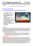
Manual Issue Number; R3, Date May 2013
GW11L1R3
USER MANUAL
TLV1000 SERIES THYRISTOR STACKS
Caledon Controls Ltd
Tel +44 (0)1555 773355
Fax +44 (0)1555 772212
Unit 2 Block 4, Castlehill Ind. Est., Carluke, Lanarkshire, Scotland, ML8 5UF
Website www.caledoncontrols.co.uk Email [email protected]
User Manual
TLV1000 Series Thyristor Stacks (80A to 250A)
REVISION HISTORY
R1
First issue June 2012
Preliminary information, may be subject to change
R2
June 2012
Added information on toggling 'comms established' bit and
other minor changes
R3
May 2013
Added information on Profinet and other fieldbus networks
and revised information regarding config. parameters set
by jumpers 3A to 3C.
Caledon Controls Ltd.
Page 2
User Manual
TLV1000 Series Thyristor Stacks (80A to 250A)
Table of Contents
Revision History . . . . . . . . . . . . . . . . . . . . . . . . . . . . . . . . . . . . . . . . . . . . . . . . . . . . . . . . . . . . . . Page 2
Contacting Us . . . . . . . . . . . . . . . . . . . . . . . . . . . . . . . . . . . . . . . . . . . . . . . . . . . . . . . . . . . . . . . . . Page 4
Important Safety Information . . . . . . . . . . . . . . . . . . . . . . . . . . . . . . . . . . . . . . . . . . . . . . . . . . . Page 4
General Description . . . . . . . . . . . . . . . . . . . . . . . . . . . . . . . . . . . . . . . . . . . . . . . . . . . . . . . . . . . Page 4
Specifications . . . . . . . . . . . . . . . . . . . . . . . . . . . . . . . . . . . . . . . . . . . . . . . . . . . . . . . . . . . . . . . . . Page 4
Dimensions . . . . . . . . . . . . . . . . . . . . . . . . . . . . . . . . . . . . . . . . . . . . . . . . . . . . . . . . . . . . . . . . . . . Page 5
Installation . . . . . . . . . . . . . . . . . . . . . . . . . . . . . . . . . . . . . . . . . . . . . . . . . . . . . . . . . . . . . . . . . . . . Page 5
General Installation Requirements . . . . . . . . . . . . . . . . . . . . . . . . . . . . . . . . . . . . . . . . . . . Page 5
Mounting . . . . . . . . . . . . . . . . . . . . . . . . . . . . . . . . . . . . . . . . . . . . . . . . . . . . . . . . . . . . . . . . . Page 6
Cover Removal and Replacement . . . . . . . . . . . . . . . . . . . . . . . . . . . . . . . . . . . . . . . . . . . Page 6
Wiring . . . . . . . . . . . . . . . . . . . . . . . . . . . . . . . . . . . . . . . . . . . . . . . . . . . . . . . . . . . . . . . . . . . . Page 7
Recommended Power Cable Sizes . . . . . . . . . . . . . . . . . . . . . . . . . . . . . . . . . . . . . Page 7
Power Connections and Auxiliary Line Connection . . . . . . . . . . . . . . . . . . . . . . . Page 7
Signal Wiring . . . . . . . . . . . . . . . . . . . . . . . . . . . . . . . . . . . . . . . . . . . . . . . . . . . . . . . . . Page 7
Control Board Connector Assignments . . . . . . . . . . . . . . . . . . . . . . . . . . . . . . . . . . . . . . . Page 8
Commissioning and Operation . . . . . . . . . . . . . . . . . . . . . . . . . . . . . . . . . . . . . . . . . . . . . . . . . Page 8
Configuration Jumpers . . . . . . . . . . . . . . . . . . . . . . . . . . . . . . . . . . . . . . . . . . . . . . . . . . . . . Page 8
Operation of Jumpers 3A to 3C in Setup Mode / Communications Network
Address and Baud Rate . . . . . . . . . . . . . . . . . . . . . . . . . . . . . . . . . . . . . . . . . . . . . . . . . . . . Page 9
Preset Potentiometers - Adjusting the Response Speed and Voltage Span . . . . . . . Page 9
Control Setpoints . . . . . . . . . . . . . . . . . . . . . . . . . . . . . . . . . . . . . . . . . . . . . . . . . . . . . . . . . Page 10
Controlled Parameters . . . . . . . . . . . . . . . . . . . . . . . . . . . . . . . . . . . . . . . . . . . . . . . Page 10
Communications Data . . . . . . . . . . . . . . . . . . . . . . . . . . . . . . . . . . . . . . . . . . . . . . . . . . . . . Page 10
LED Indicators . . . . . . . . . . . . . . . . . . . . . . . . . . . . . . . . . . . . . . . . . . . . . . . . . . . . . . . . . . . Page 12
Maintenance . . . . . . . . . . . . . . . . . . . . . . . . . . . . . . . . . . . . . . . . . . . . . . . . . . . . . . . . . . . . . . . . . Page 12
Semiconductor Fuse Types . . . . . . . . . . . . . . . . . . . . . . . . . . . . . . . . . . . . . . . . . . . . . . . . Page 12
Ordering Information . . . . . . . . . . . . . . . . . . . . . . . . . . . . . . . . . . . . . . . . . . . . . . . . . . . . . . . . . Page 13
Caledon Controls Ltd.
Page 3
User Manual
TLV1000 Series Thyristor Stacks (80A to 250A)
CONTACTING US
Please feel free to contact us by telephone, e-mail or fax if you require further information or advice on the
application, installation or maintenance of these units. Contact details are on the front of this manual.
IMPORTANT SAFETY INFORMATION
WARNING - SERIOUS DANGER OF ELECRIC SHOCK!
These thyristor stacks must be earthed. The earthing arrangements must be able to carry the fault current associated with a
short circuit of the main load circuit to the metalwork of the stack, until the protection device opens.
Thyristor stacks must never be used as a means of supply isolation, as even in the 'off' state lethal leakage currents will flow.
An independent means of isolation, complying with local standards must always be fitted.
The clear polycarbonate cover provides protection against accidental contact with live parts, and must never be removed
unless the main supply has been isolated elsewhere. Busbars and circuitry on the printed circuit boards under this cover carry
the full line voltage. The stacks are intended for mounting in an enclosure which requires a tool to gain access.
Maintenance and installation work on these units should only be carried out by suitably qualified and trained personnel who
have read and are familiar with the contents of this manual.
Additional information is provided under ‘Installation – General Requirements’.
GENERAL DESCRIPTION
A range of single phase thyristor stacks with digital communications facilities for use with transformer loads or other loads
requiring phase angle control.
SPECIFICATIONS
Voltage Rating
Up to 480V nominal supply voltage. (Isolation between the main supply and the 24V
control circuits meets the requirements for reinforced insulation, overvoltage
category III for supply voltages up to 300V line to earth)
Current Ratings (at 500C ambient)
80A, 125A, 160A, 200A, 250A.
Supply Frequency (Main terminals)
50Hz +/- 8% or 60Hz +/- 8%
Control Circuit Supply Voltage
24V DC +/- 20%.
Control circuit supply current
Without fan (80A model)
With fan (125A to 200A)
With fan (250A model)
Dimensions
All current ratings have the same dimensions:
Height - excluding mounting clamps
290mm
Width
136mm
Depth
265mm
High Current Connections
M8 studs (Supply at top, load at bottom, earth at bottom).
Control Wiring Connections
Plug and socket connections accepting wire size up to 1.5mm2
Operating Temperature Range
0-50 degrees C.
Analogue Inputs
(Not isolated from 24V supply)
0-5V, 1-5V, 0-10V, 0-20mA, 4-20mA, potentiometer, (jumper selectable)
Analogue input 1 - Control input
Analogue input 2 - Current control / current limit
Digital Inputs
Activated by link / contact closure or 5 to 24V.
Digital Input 1- Enable (stack disables within 20ms when disabled)
Digital Input 2 - Not set = phase angle; set = soft start burst fire control
Communications
Various Fieldbus types supported in data exchange mode only, using HMS
Anybus CompactCom plug-in modules.
Caledon Controls Ltd.
150mA
1,150mA
1,650mA
Page 4
User Manual
TLV1000 Series Thyristor Stacks (80A to 250A)
Clearanc e for
Cooling Airflow
100 mm
DIMENSIONS
136 mm
Clearance for
Cooling Airflow
100 mm
350mm
290mm
Distanc e from
Bottom fixing c enters
to base of stac k
= 15 mm
325 mm
Depth
265 mm
86 mm
INSTALLATION
General Installation Requirements
The following notes are a guide to ensuring sound system design, and compliance with the requirements of the European Low
Voltage Directive and other international standards.
The stacks should be installed in a cabinet requiring a tool to gain access, and access should be restricted to suitably trained
and qualified personnel. Provision should be made to exclude conductive pollution (eg graphite dust) from the cabinet, and to
avoid condensation.
Caledon thyristor stacks are designed with an impulse withstand voltage (power circuits to earth) of 4kV. This meets the
requirements of IEC and European standards for installation (over-voltage) category 3, and supply voltage (line to earth) up to
300V (AC RMS). This corresponds to 520V line to line on most distribution systems, in which the distribution transformer is star
connected with earthed star point. This does not preclude the use of the stacks in higher voltage systems (provided the
thyristor devices are suitably rated), but the over-voltage category will be reduced to 2 and precautions may be necessary (eg
surge arrestors) to limit the expected impulse voltage level, if systems compliance with the above standards is required.
All stacks in the TLV range incorporate an integral semiconductor fuse. This is intended to provide short circuit protection for
the thyristor devices, by limiting the peak half cycle surge current and total energy let through. It only provides limited protection
against long term overload. The stack ratings are co-ordinated with standard HBC fuse values, and the supply cables should be
protected with gL / gG fuses or circuit breakers of current rating the same as, or lower than the stack. All the stacks with fan
cooling also incorporate automatically resetting thermal cut outs, which monitor the temperature of the heatsink, and ensure
that it does not rise to an unsafe level.
The stacks must be fitted with a protective earth conductor, and the earth connection must be capable of carrying the
prospective fault current for the main load circuit until the protective fuse blows. An important reason for this is to protect
against short circuit to ground which might occur in one of the semiconductor modules, should the internal structure rupture
under severe fault conditions. Provided the correct semiconductor fuses are fitted, which limit the maximum energy let-through
under short circuit conditions, a short cable of 6mm2 cross section connecting between the stack earth stud and the chassis
Caledon Controls Ltd.
Page 5
User Manual
TLV1000 Series Thyristor Stacks (80A to 250A)
plate will provide an adequate local earth. Care must be taken to ensure that the panel in which the stack is installed is
adequately earthed, with an earth loop impedance less than 0.03✡ (400 / 230V, 800A system), and taking account of local
regulations.
The stacks are rated for a maximum ambient operating temperature of 50OC . This refers to the ambient air temperature
entering the heatsink at the base of the stack. The design of an installation must however take into account the ratings of
cables and other switchgear within the cabinet. Elevated temperatures also shorten the life of some electronic components,
notably electrolytic capacitors, which dry out. A major cause of elevated temperatures in a cabinet containing thyristor stacks is
the power dissipated by the thyristor devices, which may be approximated in watts as 1.5 x (RMS current) x (Number of
controlled lines). The exhaust air temperature from the stack will be higher than ambient by up to 20OC. It is not good practice
to mount other items of control gear directly in the exhaust airflow. In particular the current carrying capability of fuses or circuit
breakers will be significantly reduced if this is done. A tidy solution is to mount circuit breakers or fuses supplying the stack on a
sub-chassis mounted forward from the main chassis on which the stack is mounted. The exhaust air then passes behind these
components. Alternatively they should be mounted to the side of the thyristor stack. Thyristor stacks should not be mounted
one above the other, as this will significantly derate the upper unit, which, for rating purposes will be operating in an ambient
equal to the exhaust air temperature of the lower unit. Heat from the thyristors, together with that dissipated by the
semiconductor fuses will also raise the temperature of the stack busbars to which outgoing cables are connected, and high
temperature cables should be used. The cross-section of the cables and their ventilation will influence the temperature of the
connection studs, and the guide in the wiring section of this manual shows recommended cross sections.
Consideration must be given to fault conditions. In particular a short circuited thyristor could result in loss of control of the load
current. If this could cause a dangerous temperature to arise in the controlled load, then an independent means of monitoring
and switching off the current should be provided. This could take the form of an independent over-temperature controller
switching a contactor or under voltage release on a circuit breaker fitted in the main supply lines. Contacts should be arranged
to de-energise in the alarm (over temperature) state. European standard EN 60519-2 Safety in electroheat installations, part 2:
Particular requirements for resistance heating equipment, para 13.3 requires independent protection of electronic heating
controllers and frequently operated heating control contactors, where temperature rise in the load could otherwise be excessive
under fault conditions.
Independent provision for electrical isolation of the power and control circuit power supply must be provided.
Mounting
The stack must be mounted vertically, with the load terminal (and fan if fitted) at the bottom of the unit. Allow a minimum of
100mm above and below the stack body. to allow free airflow. Do not mount stacks one above the other. The stacks are
designed to be mounted closely side by side in multi-zone applications. We recommend a minimum gap between units of
15mm.
The mounting arrangement is shown in figure 2. Screw the upper and lower mounting brackets (1 and 2) to the mounting plate
using M6 x 16mm screws or similar and plain washers, but do not fully tighten. (Suitable holes should be drilled and tapped in
the mounting plate, dimensions on page 5). Hook the stack over the lower mounting bracket, and raise the upper mounting
bracket to the limit allowed by the slotted holes so that the stack may be installed against the mounting plate and the bracket
hooked down over it. Tighten up first the screws on the top bracket, and then the lower bracket.
Cover Removal and Replacement
A 3-part clear polycarbonate cover is provided. The top and bottom cable entry covers are held in place by the front cover.
Caledon Controls Ltd.
Page 6
User Manual
TLV1000 Series Thyristor Stacks (80A to 250A)
To remove the covers:1
2
3
Remove the M5 screws which fasten the front cover to pillars which extend from the printed circuit board.
Grip the front cover at the top centre and pull forward. The cover will unclip.
The top and bottom cover plates are now free to be lifted off.
To replace the covers
1
Line and load cables must be fed through the slots provided in the top and bottom covers. The top cover is
provided with an additional slot for the auxiliary line cable. The bottom cover has two slots for the control cables and a
slot for the earth cable.
2
Slide the ears on the top and bottom covers into the slots in the stack sides.
3
Clip the bottom ears of the front cover into the slots in the side of the stack, so that the front cover traps the bottom
cover against the crossbar.
4
Clip the top ears of the front cover over the top cover and into the slots in the side of the stack. Press home on top to
secure.
5
Fit the M5 front cover retaining screws.
Wiring
Recommended Power Cable Sizes
The following is a guide only, as installation conditions will vary. A maximum control cabinet internal temperature of 45OC has
been assumed, with cables routed in free air in the immediate vicinity of the stack, and passing into trunking in groups of three.
The cable protective fuse or circuit breaker rating has been assumed to be equal to the stack current rating. A cable suitable for
operating at 90OC has been assumed. A high temperature cable is required because the semiconductor fuses and the
thyristors run hot, and contribute to the heating of the cable. Use of cable of smaller cross section may result in overheating of
the cable / fuses.
STACK RATING
CABLE X SECTION
80A
125A
160A
200A
250A
25mm2
50mm2
70mm2
120mm2
120mm2 (Temperature rating 120OC)
Power Connections and Auxiliary Line Connection
Use the guide in the previous paragraph when determining cable type and cross section. Cables should be connected using
heavy duty tube type ring crimp terminals. The stud diameter is 8mm.
The terminal marked ‘LINE’ is connected to the supply via a suitable fuse or circuit breaker (see section on General
Requirements). The terminal marked ‘LOAD’ is connected to one end of the load. The other end of the load may be connected
(depending on the voltage rating of the thyristor stack) either to a second supply line via a fuse / circuit breaker, or to the supply
neutral. A connection must be made from this end of the load to the terminal on the top of the control card marked ‘Aux Line’.
This connection is required to enable the controller to synchronise to the supply frequency and to measure the line and load
voltages. This connection should be wired with cable of 1mm2 or 1.5mm2 cross section. If this connection is to a supply line
(rather than neutral) the cable should be protected at source against short circuit by a fuse or circuit breaker of 6A rating.
A protective earth connection of suitable cross section should be made to the stud at the top of the unit. More information is
provided under ‘Installation - General Requirements’.
Note that all studs are fitted with a plain and spring washer. The recommended tightening torque is 12Nm
Signal Wiring
Signal cables should, as far as possible, be segregated from power cables, and long runs parallel to power cables should be
avoided. Care should be taken to avoid signal flow and return paths which form loops enclosing a large area. The flow and
return paths should run parallel to each other.
Signal connections are made direct to the printed circuit board connectors. Connectors are suitable for cable up to 1.5mm2
cross section. Note that all connectors are unpluggable for ease of maintenance.
Caledon Controls Ltd.
Page 7
User Manual
TLV1000 Series Thyristor Stacks (80A to 250A)
Control Board Connector Assignments
Number
1
Function
+3.3V Output
Comment
Supply to energise a single 10k ohm potentiometer for use with
an analogue input
2
3
4
5
6
7
Analogue input 1 +
Analogue input 2 +
Analogue inputs 0V
Digital input 1 - Stack Enable
Digital input 2 - Phase angle (not activated)
/ Soft start burst fire (activated)
Common for digital inputs
8
9
Alarm contact N/C
Alarm contact N/O
10
Common for alarm contacts
11
+24V Supply for control circuits and fan
12
0V Supply
Digital inputs are activated by applying a voltage of 5V to 24V
DC between the input and the input common. Voltage may be
either polarity. These terminals are galvanically isolated from all
other terminals.
Volt free contacts. Maximum rating 250V AC resistive 2A, 30V
DC resistive 2A. Isolation from 24V circuits meets requirements
for basic insulation, overvoltage category II
+24V supply should be protected with a 6A antisurge fuse or
circuit breaker.
Fieldbus connections are made to the connector on the Anybus CompactCom (grey) module on the left of the control card and
will follow the standard for the relevant fieldbus.
COMMISSIONING AND OPERATION
Configuration Jumpers
The position of various configuration jumpers etc is shown in the PCB layout drawing below.
Set the jumpers for analogue inputs as required according to the following tables. Note that if inputs with offset are required
(1-5V, 4-20mA) then both analogue inputs must have offsets.
Analogue Input 1
0-5V
0-10V
0-20mA
1-5V
4-20mA
10k ohm
Potentiometer Input
Jumper 1A
Jumper 1B
on
on
on
on
on
Jumper 1C
Jumper 3A
on
on
Caledon Controls Ltd.
on
on
Page 8
User Manual
TLV1000 Series Thyristor Stacks (80A to 250A)
Analogue Input 2
0-5V
0-10V
0-20mA
1-5V
4-20mA
10k ohm
Potentiometer Input
Jumper 3B
Jumper 3C
Jumper 2A
Jumper 2B
on
on
on
on
on
Jumper 2C
Jumper 3A
on
on
Communications
Controlled parameter for setpoint 1
on
on
Read Write if not fitted / Read only if fitted
V2 if not fitted / Power if fitted*
*If comms are in read / write mode then this jumper is ignored and parameter must be set in status register 2.
Jumper 4
Activate setup mode
In setup mode jumpers 3A to 3C enable setting of additional parameters by counting flashes of the
Status LED (see section below):3A
Set communications address
3B
Set communications baud rate
3C
Set burst fire cycle time
default value 10s @ 50% duty cycle.
Operation of Jumpers 3A to 3C in Setup Mode / Communications Network Address and Baud Rate
When jumper 4 is removed, jumpers 3A to 3C take on their setup roles. Before removing jumper 4, jumpers should be
removed from 3A to 3C. Then, when jumper 4 is removed, initially there will be no change to the parameters which are
adjustable by 3A to 3C. When the stack is first shipped these parameters will have default values. The stack is now waiting for
one of the jumpers 3A to 3C to be fitted. When it is fitted the Status LED will start flashing, and the number of flashes counted
determines the value of the parameter. When the required number of flashes has been observed the jumper is removed. The
new values are stored when the jumper 4 is replaced and the stack reverts to normal operating mode. (As shown in the table
below, for addresses the first flash represents zero, the second flash represents 1 etc.; for burst fire cycle time the first flash
represents 5s, the second flash represents 6s etc. Depending on the fieldbus fitted, the address and / or baud rate jumper may
have no function.
3A
3B
3C
Counts address from 0 to 63
Changes baud rate - Baud rate 1, baud rate 2, baud rate 3 (increasing)
Counts burst fire cycle time in seconds from 5 to 30 seconds.
While undertaking the above procedure, normally only one of the jumpers 3A to 3C should be fitted at any one time. If the
count is allowed to exceed the above ranges the value will not be updated and the LED will stop flashing. If two jumpers are
fitted counting will stop and no value will be updated. If all 3 jumpers are fitted together all parameters will revert to the
default values when jumper 4 is replaced.
Note that while jumper 4 is removed the span adjustment potentiometer does not operate.
Table of Jumper 3A to 3C Count Values / Default Values
Fieldbus
3A Address
3B Baud Rate
Network Type
(Profinet Station Name)
Range
Default
Range
Default
125k, 250k,
DeviceNet
0 to 63
63
125k
500k
N/A (Auto
Profibus
0 to 63
63
N/A
detect)
Thyristor-000
Profinet
to
Blank
N/A
N/A
Thyristor-063
Modbus TCP
N/A
255
N/A
N/A
9,600, 19,200,
Modbus RTU
0 to 63
63
9,600
57,600
3C Burst fire Cycle Time
Range
Default
5 - 30s
10s
5 - 30s
10s
5 - 30s
10s
5 - 30s
10s
5 - 30s
10s
For Ethernet based networks the IP address and subnet mask cannot be set from the TLV1000. They must be set using the
user's network configuration software, or alternatively the Anybus IPconfig utility which is available from the downloads page of
our website, www.caledoncontrols.co.uk or from the HMS website, www.hms.se
Preset Potentiometers - Adjusting the Response Speed and Voltage Span
Two potentiometers, P3 and P4 are available for adjustment by the user. These are accessible with the front cover fitted. None
of the other potentiometers should be adjusted at all otherwise the calibration will be compromised and difficult to
reinstate.
Caledon Controls Ltd.
Page 9
User Manual
TLV1000 Series Thyristor Stacks (80A to 250A)
P4 (upper)
Adjusts the response speed (phase angle ramp speed) for setpoints 1 and 2 when controlling in phase angle
mode. Response is fastest when the potentiometer is fully anticlockwise. This potentiometer can be adjusted while the stack is
operational. It does not affect the soft start ramp time in burst fire mode, which is preset at approximately 10 cycles of the
supply. It does affect the speed of response of current limit (controlled by setpoint 2) when in burst fire mode.
P3 (lower)
Is used to set the voltage span of the controller to the supply voltage. (Adjustable over the range 300V to 600V
on 480V model). There are two possibilities for setting this:1
If communications are established the span voltage may be read in production register 8 and observed while adjusting
the potentiometer.
2
If communications are not available then the simplest way to span the stack is to run it in phase angle mode, controlling
V2 with a setpoint of 100%. The potentiometer is adjusted until the voltage measured across the load is the desired span
voltage. Note that this value is best approached from below, and that the supply voltage must be greater than or equal to the
desired voltage. If the supply voltage is low then a lower setpoint may be chosen. For example, with a setpoint of 80% the
output voltage should be („0.8 x Voltage span).
Control Setpoints
Two setpoints are active at any one time, and may each control a different variable (eg V2 and I). A setpoint takes control if its
controlled variable rises above the setpoint setting.
If communications are set as read only, setpoints 1 and 2 will be derived from analogue inputs 1 and 2. If operation in current
control mode is required (analogue input 2) analogue input 1 must be tied high. If operation is required in voltage2 or power
mode (analogue input 1) with current limit only at the stack rating, then analogue input 2 must be tied high.
If communications are set as read/write then each of the two setpoints may be sourced either from the analogue input or from a
comms register, as selected by bits in status register 2 in the write / consumption registers. If current limit at the stack rated
current is required the current setpoint must be set to 100%.
Controlled Parameters
Setpoint 2 always controls current (initial versions of software), and its primary function will be as a current limit setpoint.
If communications are configured as read only Setpoint 1 can be set to control either V2 or Power, as determined by jumper 3C.
If communications are configured as read / write the controlled parameter for setpoint 1 is determined by the comms using
status register 2, and other parameters are available. Jumper 3C is ignored.
Communications Data
Communications may be configured as read only or read/write by jumper 3B.
In read only mode (jumper 3B fitted) the stack does not care whether or not communications are established. All operating
parameters are determined by the hardware. The user may read parameters such as load voltage etc to determine the
operating state.
In read / write mode (jumper 3B not fitted) the operation of the stack can also be controlled by the user (eg sending setpoints).
In this mode the stack will not operate unless Status Register 2 bits 1 and 2 are activated by the user. Bit 1 is an additional
'enable'. This performs a similar function to the hardware enable, and if it is not set the stack will be disabled but will not alarm.
Bit 2, 'comms established' must be toggled approximately once per second. If it is not toggled the stack will disable and alarm.
The purpose of this is to ensure that if communications are lost the stack will disable rather than continuing to operate with the
same setpoint as when communication was lost. The toggle function may be performed by the user’s own timer, or
alternatively the ‘heartbeat’ (bit 9) in Status Register 1 may be read by the user and reflected back to status register 2 bit 2. In
addition the user may write values (eg an incrementing number) into Consumption Register 4 which will be returned in
Production Register 15 enabling the operation of the communication loop to be ascertained.
The function of the communications registers is defined in the tables below. Each register is 16 bits wide. Numerical
parameters are expressed as 16 bit binary values representing the parameter value in engineering units multiplied by 10,
except energy consumption which is in kWh not multiplied by 10.
Setpoints must be supplied in percent 0.0-100.0, multiplied by 10, whatever the controlled parameter:Voltage setpoint
Current setpoint
Power setpoint
Voltage2 setpoint
Current2 setpoint
100% corresponds to stack voltage span
100% corresponds to stack rated current
100% corresponds to (Voltage span x rated current)
100% corresponds to voltage span, but operation is non linear so that
voltage output = (voltage span) x „(setpoint % / 100)
100% corresponds to current rating, but operation is non linear so that
current output = (current rating) x „(setpoint % / 100)
Caledon Controls Ltd.
Page 10
User Manual
TLV1000 Series Thyristor Stacks (80A to 250A)
Read Only (Production) Registers (19 registers are configured)
Number
Name
Additional Information
1
Status Register 1
Operating status
Bit 0 Line present
Bit 1 Phase lock achieved
Bit 2 Heatsink temperature OK
Bit 3 Phase angle / burst fire mode (burst fire when set)
Bit 4 Hardware enable
Bit 5 Stack enabled
Bit 6 Alarm
Bit 7 Setpoint 1 Controlling (not set) (default) / setpoint 2 controlling (set)
Bit 8 Setup mode (not set) / Run mode (set)
2
3
4
5
Status Register 2
Line Voltage
Load Voltage
Load Current
6
7
8
9
10
11
12
13
14
Load Power (%)
Firing Angle
Voltage Span
Working Setpoint
Analogue setpoint 1
Analogue setpoint 2
Setpoint 1 (comms)
Setpoint 2 (comms)
Energy Consumption
(kWh)
User Value
15
Bit 9 Heartbeat. This bit is toggled once per second
The same as Consumption Status Register 2
In burst fire mode these values show the voltage and current in real time (ie they
switch on and off)
As a percentage of Span voltage x stack rated current
.0-180 degrees where 180 corresponds to fully conducting
In Volts - The value set on the span potentiometer
In %
In %
In %
In %
Energy supplied to the load since last reset. Maximum value before roll over is
50,000 kWh.
This register returns the value entered in Consumption Register 4
Write (Consumption) Registers (6 registers are configured)
Number
Name
Additional Information
1
Status Register 2
Bit 0 Digital Input 2 Set = Burst fire, Not set = Phase angle
Bit 1 Comms enable
Bit 2 Comms established
Bit 3 Use comms for setpoint 1 (analogue setpoint 1 not used)
Bit 4 Use comms for setpoint 2 (analogue setpoint 2 not used)
When comms are in
read / write mode bits 5
and 6 MUST be set as
required.
Bit 5
Bit 6
0
0
Setpoint 1 controlled parameter = V2
1
0
Setpoint 1 controlled parameter = Power
0
1
Setpoint 1 controlled parameter = Volts
1
Bit 7
(Bits 7 to 10 are not
implemented in the first
software versions.
Setpoint 2 always
controls current).
Bit 8
1
Setpoint 1 controlled parameter = I2
If not set, setpoint 2 controls current. If set, setpoint 2 parameter is defined
by bits 8 and 9
Bit 9
0
0
Setpoint 2 controlled parameter = V2
1
0
Setpoint 2 controlled parameter = Power
0
1
Setpoint 2 controlled parameter = Volts
1
1
Setpoint 2 controlled parameter = I2
Bit 10 Toggle high to reset energy counter.*
2
3
4
Setpoint 1
Setpoint 2
User Value
Active if Bit 3 in SR2 is set. Range 0.0 to 100.0%
Active if Bit 4 in SR2 is set. Range 0.0 to 100.0%
A value entered in this register is returned in Production Register 15
* After the stack has reset the energy counter it will ignore this bit for 1 minute. After the energy counter is observed to have
been reset this bit must be reset by the user otherwise the energy counter will be continually reset.
Caledon Controls Ltd.
Page 11
User Manual
TLV1000 Series Thyristor Stacks (80A to 250A)
LED Indicators
Four green LED indicators (see diagram on page 8) show the operating status of the controller. (For information on the LED
indicators on the CompactCom fieldbus communications module see the information appended at the end of the manual).
If no LEDs are illuminated the 24V power supply to the driver PCB is not present - the board is unpowered.
Status LED
1 second slow flash
The board is powered but is not enabled. For the controller to enable there must be no
alarms, the hardware enable input must be activated, and if comms read / write mode is
selected the comms enable bit must be set (consumption register 1; status register 2).
Fast flicker
The board is powered and enabled and is either operating in phase angle mode or is at
zero setpoint
Fast flicker / full on
The board is powered and enabled and is operating in burst fire mode. The LED is full on in
the ‘on’ periods and fast flickers in the off periods
Off
Either the board is unpowered or the stack is in ‘Setup’ mode (jumper 4 off) and awaiting
action by the user.
_____
Alarm LED
This LED illuminates when there are no alarms. The alarm relay will be energised. The relay de-energises in the alarm state.
Alarms which cause the LED to extinguish are; Main power supply (50 / 60 Hz load power) under-voltage, loss of phase lock,
heatsink temperature too high, comms established bit in status register 2 not set (comms read / write mode only)
Dig In 1
Illuminates to indicate that digital input 1 (hardware enable) is activated.
Dig In 2
Illuminates to indicate that digital input 2 is activated; the controller will operate in soft start burst fire mode.
MAINTENANCE
Semiconductor Fuse Types
Checking or changing of any fuse must not be attempted unless both main and driver supplies are isolated. To do so
is extremely dangerous, and may also cause damage to the controller.
See ‘Cover removal and Replacement’ for instructions on how to remove and replace the cover.
The semiconductor fuses listed in the table below may be used. Consult us before using other fuse types.
Stack Current Rating
Nominal Fuse Current
Rating
Fuse I2t Rating
(Approx A2s)
Fuse Type
(BS88 Fixing Centres)
DIN43 653/80/000
80mm fixing centres
Bussmann
Siba
110A
6,800
E330100C
170M1485
20 559 20 110
M330038*
170M1317
20 282 20 125 *
100A Ferraz
125A
Bussmann
Siba
160A
15,400
F330055C
170M1469
20 559 20 160
N330039
170M1319
20 282 20 160
Ferraz
Bussmann
Siba
250A
44,000
H330057
170M1487
20 559 20 250
Q330041
170M1321
20 282 20 250
Ferraz
Bussmann
Siba
315A
77,000
J330058C
170M1488
20 559 20 300
R330042
170M1322
20 282 20 315
Bussmann
Siba
350A (DIN 00 size)
110,000
80A
160A
200A
250A
170M2670
20 189 20 350
*125A rating
The line terminal fuse support pillar has alternative mounting points on the heatsink to cater for the different pitch of
Caledon Controls Ltd.
Page 12
User Manual
TLV1000 Series Thyristor Stacks (80A to 250A)
alternative fuses. If necessary unscrew the pillar from the heatsink and re-fit in the alternative position.
Note that a serrated lockwasher is fitted behind the fuse on the line stud. It is most important that this is not omitted, otherwise
excessive torque may be transmitted to the stud when the fuse / cable retaining nut is tightened. The recommended tightening
torque for these nuts is 12Nm
ORDERING INFORMATION
Select the desired options from the following table (the nominal supply voltage range is for information only):Typical example TLV1000-125A-480V-24V-DeviceNet
Series
Current Rating
TLV1000
80A
125A
160A
200A
250A
Load Supply
Voltage
690V
480V
230V
150V
Control Supply Voltage
Communications
24V DC
None
DeviceNet
Profibus DP
Profinet
Modbus TCP
Modbus RTU
Other*
Nominal load supply
voltage range
# 500V to 690V
380V to 480V
200V to 270V
115V to 150V
* Please enquire
# Over voltage category 2.
Caledon Controls Ltd.
Page 13
About the Anybus CompactCom DeviceNet 5
1.3 Front View
#
1
Item
Network Status LED
2
Module status LED
3
DeviceNet Connector
4
M12 Female Connector
1
2
3
1
5
1
5
4
5
2
M12 Male Connector
Network Status
State
Off
Green
Flashing Green (1 Hz)
Red
Flashing Red (1 Hz)
Alternating Red/Green
Indication
Not online / No power
On-line, one or more connections are established
On-line, no connections established
Critical link failure
One or more connections timed-out
Self test
Module Status
State
Off
Green
Flashing Green (1 Hz)
Red
Flashing Red (1 Hz)
Alternating Red/Green
Indication
No power
Operating in normal condition
Missing or incomplete configuration, device needs commissioning
Unrecoverable Fault(s)
Recoverable Fault(s)
Self test
DeviceNet Connector
This connector provides DeviceNet connectivity.
Pin
1
Signal
V-
2
3
4
5
CAN_L
SHIELD
CAN_H
V+
Description
Negative bus supply voltagea
CAN low bus line
Cable shield
CAN high bus line
Positive bus supply voltagea
a. DeviceNet bus power. For more information, see D-48 “Technical Specification”.
Anybus CompactCom DeviceNet
Doc.Rev. 2.10
Doc.Id. HMSI-168-51
About the Anybus-CC PROFIBUS DP-V1 5
1.3 Front View
#
1
Item
Operation Mode
2
Status
3
PROFIBUS Connector
4
M12 Female Connector
5
M12 Male Connector
5
1
1
2
3
9
1
6
4
5
2
Operation Mode
State
Off
Green
Flashing Green
Flashing Red (1 flash)
Flashing Red (2 flashes)
Indication
Not online / No power
Data exchange
Clear
Parametrization error
PROFIBUS Configuration error
Comments
See “Parametrization Data Handling” on page 15
See “Configuration Data Handling” on page 16
Status
State
Off
Green
Flashing Green
Red
Indication
Not initialized
Initialized
Initialized, diagnostic event(s) present
Exception error
Anybus CompactCom PROFIBUS DP-V1
Doc.Rev. 2.20
Comments
Anybus state = ‘SETUP¨’ or ‘NW_INIT’
Anybus module has left the ‘NW_INIT’ state
Extended diagnostic bit is set
Anybus state = ‘EXCEPTION’
Doc.Id. HMSI-168-66
About the Anybus-CompactCom PROFINET IO 5
1.3 Front View
#
Item
1
1
2
3
4
8
1
Network Status LED
Module Status LED
Link/Activity LED
Ethernet Interface
2
4
3
Network Status LED
Note: A test sequence is performed on this LED during startup.
LED State
Off
Description
Offline
Green
Online (RUN)
Green, flashing
Online (STOP)
Comments
- No power
- No connection with IO Controller
- Connection with IO Controller established
- IO Controller in RUN state
- Connection with IO Controller established
- IO Controller in STOP state
Module Status LED
Note: A test sequence is performed on this LED during startup.
LED State
Off
Green
Green, 1 flash
Green, 2 flashes
Red
Red, 1 flash
Red, 2 flashes
Red, 3 flashes
Red, 4 flashes
Description
Not Initialized
Normal Operation
Diagnostic Event(s)
Blink
Exception Error
Configuration Error
IP Address Error
Station Name Error
Internal Error
Comments
No power - or - Module in ‘SETUP’ or ‘NW_INIT’ state
Module has shifted from the ‘NW_INIT’ state
Diagnostic event(s) present
Used by engineering tools to identify the node on the network
Module in state ‘EXCEPTION’
Expected Identification differs from Real Identification
IP address not set
Station Name not set
Module has encountered a major internal error
Description
No Link
Link
Activity
Comments
No link, no communication present
Ethernet link established, no communication present
Ethernet link established, communication present
LINK/Activity LED
LED State
Off
Green
Green, flickering
Ethernet Interface
The Ethernet interface operates at 100 Mbit, full duplex, with autonegotiation enabled as default.
IMPORTANT:
For information on how to connect the PROFINET cable, see “Protective Earth (PE) Requirements” on page 150.
Anybus CompactCom PROFINET IO
Doc.Rev. 2.15
Doc.Id. HMSI-168-74