1
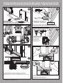
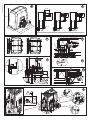
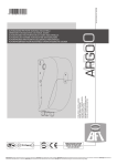
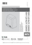
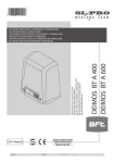
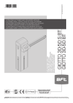
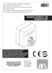
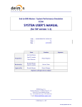
D811972 00100_02 11-04-14
DEIMOS BT A 400
DEIMOS BT A 600
ISTRUZIONI D’USO E DI INSTALLAZIONE
INSTALLATION AND USER’S MANUAL
INSTRUCTIONS D’UTILISATION ET D’INSTALLATION
INSTALLATIONS-UND GEBRAUCHSANLEITUNG
INSTRUCCIONES DE USO Y DE INSTALACION
INSTALLATIEVOORSCHRIFTEN
ATTUATORE PER CANCELLI SCORREVOLI A CREMAGLIERA
ACTUATOR FOR RACK SLIDING GATES
ACTIONNEUR POUR PORTAILS COULISSANTS A CREMAILLERE
ANTRIEB FÜR ZAHNSTANGEN-SCHIEBETORE
SERVOMOTOR PARA CANCELAS CORREDERAS DE CREMALLERA
ACTUATOR VOOR SCHUIFHEKKEN MET TANDHEUGEL
Attenzione! Leggere attentamente le “Avvertenze” all’interno! Caution! Read “Warnings” inside carefully! Attention! Veuillez lire attentivement les Avertissements qui se trouvent à l’intérieur!
Achtung! Bitte lesen Sie aufmerksam die „Hinweise“ im Inneren! ¡Atención¡ Leer atentamente las “Advertencias” en el interior! Let op! Lees de “Waarschuwingen” aan de binnenkant zorgvuldig!
A
B
> 25mm
60-70mm
2
mm
,75
5x0
3x
1.5
m
3x1
m2
2x0.75mm2
.5m
m2
2x1.5mm2
“X”=Cremagliera (FIG J), Rack (FIG J),
PREDISPOSIZIONE TUBI,
RG58
3x1.5mm2
TUBE ARRANGEMENT,
PRÉDISPOSITION DES TUYAUX, VORBEREITUNG DER LEITUNGEN,
DISPOSICIÓN DE TUBOS, VOORBEREIDING LEIDINGEN.
Crémaillère (FIG J), Zahnstange (FIG J),
Cremallera (FIG J), Tandheugel (FIG J)
C
3
17mm + “X”
Predisposizione fissaggio motore, Preparation for motor mounting,
Aménagement fixation moteur, Vorbereitung Motorbefestigung,
Disposición fijación del motor, Voorbereiding bevestiging motor.
4
> 10mm
D
2
1
3A
Montaggio motore,
Mounting the motor,
Montage moteur,
Montage Motor,
Montaje del motor,
Montage motor.
3B
E
Y
F
E1
Y + 50 mm
Montaggio accessori trasmissione, Mounting drive accessories,
Montage accessoires transmission, Montage Antriebszubehör,
Montaje de accesorios transmisión, Montage accessoires overbrenging.
2 -
DEIMOS BT A 400 - DEIMOS BT A 600
Fissaggio staffe finecorsa (dx e sx), Fastening limit switch brackets (RH/LH),
Fixation étriers fin de course (drt et gch), Befestigung Bügel Anschläge (rechts und links),
Fijación abrazaderas final de carrera (der. e izq.),
Bevestiging stangen aanslag (rechts en links).
D811972 00100_02
INSTALLAZIONE VELOCE-QUICK INSTALLATION-INSTALLATION RAPIDE
SCHNELLINSTALLATION-INSTALACIÓN RÁPIDA - SNELLE INSTALLATIE
D811972 00100_02
L
K
X= 40
30
60
30
28
6
287
12
X= 37
39
8
X= 33
50
0
12
16
4
5
25
5
13
CP
CVZ
CVZ-S
N
M
OK
NO
O
2mm
N1
P
>25
50
>100
P1
17
Q
Q3
Q1
S
Q2
DEIMOS BT A 400 - DEIMOS BT A 600 -
5
WARNING! Important safety instructions. Carefully read and comply with
all the warnings and instructions that come with the product as incorrect
installation can cause injury to people and animals and damage to property.
The warnings and instructions give important information regarding safety,
installation, use and maintenance. Keep hold of instructions so that you can
attach them to the technical file and keep them handy for future reference.
GENERAL SAFETY
This product has been designed and built solely for the purpose indicated herein.
Uses other than those indicated herein might cause damage to the product and
create a hazard.
- The units making up the machine and its installation must meet the requirements
of the following European Directives, where applicable: 2004/108/EC, 2006/95/
EC, 2006/42/EC, 89/106/EC, 99/05/EC and later amendments. For all countries
outside the EEC, it is advisable to comply with the standards mentioned, in addition to any national standards in force, to achieve a good level of safety.
- The Manufacturer of this product (hereinafter referred to as the “Firm”) disclaims
all responsibility resulting from improper use or any use other than that for
which the product has been designed, as indicated herein, as well as for failure
to apply Good Practice in the construction of entry systems (doors, gates, etc.)
and for deformation that could occur during use.
- Installation must be carried out by qualified personnel (professional installer,
according to EN 12635), in compliance with Good Practice and current code.
- Before installing the product, make all structural changes required to produce
safety gaps and to provide protection from or isolate all crushing, shearing and
dragging hazard areas and danger zones in general in accordance with the
provisions of standards EN 12604 and 12453 or any local installation standards.
Check that the existing structure meets the necessary strength and stability
requirements.
- Before commencing installation, check the product for damage.
- The Firm is not responsible for failure to apply Good Practice in the construction
and maintenance of the doors, gates, etc. to be motorized, or for deformation
that might occur during use.
- Make sure the stated temperature range is compatible with the site in which the
automated system is due to be installed.
- Do not install this product in an explosive atmosphere: the presence of flammable
fumes or gas constitutes a serious safety hazard.
- Disconnect the electricity supply before performing any work on the system.
Also disconnect buffer batteries, if any are connected.
- Before connecting the power supply, make sure the product’s ratings match the
mains ratings and that a suitable residual current circuit breaker and overcurrent
protection device have been installed upline from the electrical system. Have
the automated system’s mains power supply fitted with a switch or omnipolar
thermal-magnetic circuit breaker with a contact separation that provide full
disconnection under overvoltage category III conditions.
- Make sure that upline from the mains power supply there is a residual current
circuit breaker that trips at no more than 0.03A as well as any other equipment
required by code.
- Make sure the earth system has been installed correctly: earth all the metal parts
belonging to the entry system (doors, gates, etc.) and all parts of the system
featuring an earth terminal.
- Installation must be carried out using safety devices and controls that meet
standards EN 12978 and EN 12453.
- Impact forces can be reduced by using deformable edges.
- In the event impact forces exceed the values laid down by the relevant standards,
apply electro-sensitive or pressure-sensitive devices.
- Apply all safety devices (photocells, safety edges, etc.) required to keep the
area free of impact, crushing, dragging and shearing hazards. Bear in mind the
standards and directives in force, Good Practice criteria, intended use, the installation environment, the operating logic of the system and forces generated by
the automated system.
- Apply all signs required by current code to identify hazardous areas (residual
risks). All installations must be visibly identified in compliance with the provisions
of standard EN 13241-1.
- Once installation is complete, apply a nameplate featuring the door/gate’s data.
- This product cannot be installed on leaves incorporating doors (unless the motor
can be activated only when the door is closed).
- If the automated system is installed at a height of less than 2.5 m or is accessible,
the electrical and mechanical parts must be suitably protected.
- Install any fixed controls in a position where they will not cause a hazard, away
from moving parts. More specifically, hold-to-run controls must be positioned
within direct sight of the part being controlled and, unless they are key operated,
must be installed at a height of at least 1.5 m and in a place where they cannot
be reached by the public.
- Apply at least one warning light (flashing light) in a visible position, and also
attach a Warning sign to the structure.
- Attach a label near the operating device, in a permanent fashion, with information on how to operate the automated system’s manual release.
- Make sure that, during operation, mechanical risks are avoided or relevant
protective measures taken and, more specifically, that nothing can be banged,
crushed, caught or cut between the part being operated and surrounding parts.
- Once installation is complete, make sure the motor automation settings are
correct and that the safety and release systems are working properly.
- Only use original spare parts for any maintenance or repair work. The Firm disclaims all responsibility for the correct operation and safety of the automated
system if parts from other manufacturers are used.
- Do not make any modifications to the automated system’s components unless
explicitly authorized by the Firm.
- Instruct the system’s user on what residual risks may be encountered, on the
control systems that have been applied and on how to open the system manually in an emergency. give the user guide to the end user.
- Dispose of packaging materials (plastic, cardboard, polystyrene, etc.) in accordance with the provisions of the laws in force. Keep nylon bags and polystyrene
out of reach of children.
12 -
WIRING
WARNING! For connection to the mains power supply, use: a multicore cable with
a cross-sectional area of at least 5x1.5mm2 or 4x1.5mm2 when dealing with threephase power supplies or 3x1.5mm2 for single-phase supplies (by way of example,
type H05 VV-F cable can be used with a cross-sectional area of 4x1.5mm2). To connect auxiliary equipment, use wires with a cross-sectional area of at least 0.5 mm2.
- Only use pushbuttons with a capacity of 10A-250V or more.
- Wires must be secured with additional fastening near the terminals (for example,
using cable clamps) in order to keep live parts well separated from safety extra
low voltage parts.
- During installation, the power cable must be stripped to allow the earth wire
to be connected to the relevant terminal, while leaving the live wires as short
as possible. The earth wire must be the last to be pulled taut in the event the
cable’s fastening device comes loose.
WARNING! safety extra low voltage wires must be kept physically separate from
low voltage wires.
Only qualified personnel (professional installer) should be allowed to access
live parts.
CHECKING THE AUTOMATED SYSTEM AND MAINTENANCE
Before the automated system is finally put into operation, and during maintenance
work, perform the following checks meticulously:
- Make sure all components are fastened securely.
- Check starting and stopping operations in the case of manual control.
- Check the logic for normal or personalized operation.
- For sliding gates only: check that the rack and pinion mesh correctly with 2 mm
of play along the full length of the rack; keep the track the gate slides on clean
and free of debris at all times.
- For sliding gates and doors only: make sure the gate’s running track is straight
and horizontal and that the wheels are strong enough to take the weight of the
gate.
- For cantilever sliding gates only: make sure there is no dipping or swinging
during operation.
- For swing gates only: make sure the leaves’ axis of rotation is perfectly vertical.
-For barriers only: before opening the door, the spring must be decompressed
(vertical boom).
- Check that all safety devices (photocells, safety edges, etc.) are working properly
and that the anti-crush safety device is set correctly, making sure that the force
of impact measured at the points provided for by standard EN 12445 is lower
than the value laid down by standard EN 12453.
- Impact forces can be reduced by using deformable edges.
- Make sure that the emergency operation works, where this feature is provided.
- Check opening and closing operations with the control devices applied.
- Check that electrical connections and cabling are intact, making extra sure that
insulating sheaths and cable glands are undamaged.
- While performing maintenance, clean the photocells’ optics.
- When the automated system is out of service for any length of time, activate the
emergency release (see “EMERGENCY OPERATION” section) so that the operated
part is made idle, thus allowing the gate to be opened and closed manually.
- If the power cord is damaged, it must be replaced by the manufacturer or their
technical assistance department or other such qualified person to avoid any risk .
- If “D” type devices are installed (as defined by EN12453), connect in unverified
mode, foresee mandatory maintenance at least every six months
- The maintenance described above must be repeated at least once yearly or at
shorter intervals where site or installation conditions make this necessary.
WARNING!
Remember that the drive is designed to make the gate/door easier to use and
will not solve problems as a result of defective or poorly performed installation
or lack of maintenance
SCRAPPING
Materials must be disposed of in accordance with the regulations in
force. Do not throw away your discarded equipment or used batteries
with household waste. You are responsible for taking all your waste
electrical and electronic equipment to a suitable recycling centre.
DISMANTLING
If the automated system is being dismantled in order to be reassembled at another
site, you are required to:
- Cut off the power and disconnect the whole electrical system.
- Remove the actuator from the base it is mounted on.
- Remove all the installation’s components.
- See to the replacement of any components that cannot be removed or happen
to be damaged.
THE DECLARATION OF CONFORMITY CAN BE VIEWED ON THIS WEBSITE:
WWW.BFT.IT IN THE PRODUCT SECTION.
Anything that is not explicitly provided for in the installation manual is not allowed. The operator’s proper operation can only be
guaranteed if the information given is complied with. The Firm shall
not be answerable for damage caused by failure to comply with the
instructions featured herein.
While we will not alter the product’s essential features, the Firm reserves
the right, at any time, to make those changes deemed opportune to
improve the product from a technical, design or commercial point of
view, and will not be required to update this publication accordingly.
DEIMOS BT A 400 - DEIMOS BT A 600
AVVERTENZE PER L’INSTALLATORE D811766_12
D811972 00100_02
INSTALLER WARNINGS
D811972 00100_02
INSTALLATION MANUAL
1) GENERAL INFORMATION
The DEIMOS BT A actuator is highly versatile in terms of installation options due
to the extremely low position of the pinion, the actuator’s compact nature and the
height and depth adjustment features it offers. The adjustable electronic torque
limiter provides anti-crush safety. Manual emergency operation is extremely easy
to perform using just a release lever.
Stopping at end of travel is controlled by electromechanical microswitches.
The HAMAL control panel comes with standard factory settings.
Any change must be set by means of the TRIMMER and DIP SWITCH settings.
TESTING
The HAMAL panel controls (checks) the start relays and safety devices (photocells)
before performing each opening and closing cycle.
If there is a malfunction, make sure that the connected devices are working
properly and check the wiring.
2) TECHNICAL SPECIFICATIONS
Power supply
MOTOR
400
120V 60Hz
220-230V 50/60 Hz(*)
600
120V 60Hz
220-230V 50/60 Hz(*)
Motor
24V
24V
Power input
50W
70W
Max. current demand
0,5A (230V~) - 1A
(110V~)
0,5A (230V~) - 1A
(110V~)
Pinion module (standard)
4mm (14 teeth)
4mm (14 teeth)
Leaf speed (standard)
12m/min
12m/min
Max. leaf weight - standard**
4000N (≈400kg)
6000N (≈600kg)
Pinion module (fast)
4mm (18 teeth)
4mm (18 teeth)
Leaf speed (fast)
15.5m/min
15.5m/min
Max. leaf weight - fast**
3000N (≈300kg)
3600N (≈360kg)
Max. torque
20Nm
30Nm
Impact reaction
Electronic torque
limiter
Electronic torque
limiter
Lubrication
Lifetime greased
Lifetime greased
Manual operation
Lever-operated
mechanical release
Lever-operated
mechanical release
Type of use
intensive
intensive
Buffer batteries (optional
extras)
Two 12V 1.2Ah bat- Two 12V 1.2Ah batteries
teries
Environmental conditions
from -20°C to +55°C
from -20°C to +55°C
Protection rating
IP44
IP44
Noise level
<70dBA
<70dBA
Operator weight
7kg (≈70N)
7kg (≈70N)
See Fig. K
See Fig. K
Dimensions
Usable transmitter versions:
All ROLLING CODE transmitters compatible with
.
3) TUBE ARRANGEMENT Fig.A
Install the electrical system referring to the standards in force for electrical systems
CEI 64-8, IEC 364, harmonization document HD 384 and other national standards.
4) PREPARATION FOR MOTOR MOUNTING FIG.B
Make a hole in the ground to accommodate the concrete pad, with anchors
embedded in the base plate for fastening the gearbox assembly, keeping to the
distances featured in FIG.B.
5) REMOVING THE COVER Fig.C
t 6OTDSFXUIFSFMFWBOUUXPGSPOUTDSFXT'*($SJG
t 1VTIBTJMMVTUSBUFE'*($SJGSJG
UPSFMFBTFUIFDPWFSGSPNUIFUXPSFBS
blocks (FIG.C - rif.3A e FIG.C - rif.3B).
t -JGUUIFDPWFS'*($SJG
6) MOUNTING THE MOTOR FIG.D
7) MOUNTING DRIVE ACCESSORIES FIG.E-E1
Recommended rack types (FIG.L)
8) RACK CENTRING WITH RESPECT TO PINION FIG.M-N1-O
DANGER - Welding must be performed by a competent person issued
with the necessary personal protective equipment as prescribed by
the safety rules in force FIG.L.
9) FASTENING LIMIT SWITCH BRACKETS FIG.F
10) STOPS FIG.P
DANGER - The gate must be fitted with mechanical stops to halt its
travel both when opening and closing, thus preventing the gate from
coming off the top guide. Said stops must be fastened firmly to the ground,
a few centimetres beyond the electric stop point.
Note: the safety edge P1 must be installed so that it is not triggered by the
mechanical stops.
11) MANUAL RELEASE (See USER GUIDE -FIG.3-).
Warning Do not JERK the gate open and closed, instead push it GENTLY to
the end of its travel.
12) TERMINAL BOARD WIRING Fig. G-Q
Once suitable electric cables have been run through the raceways and the automated device’s various components have been fastened at the predetermined
points, the next step is to connect them as directed and illustrated in the diagrams contained in the relevant instruction manuals. Connect the live, neutral
and earth wire (compulsory).The mains cable must be clamped in the relevant
cable gland (FIG.Q-ref.Q1) and in the grommet (FIG.Q-ref.Q2), while the earth
wire with the yellow/green-coloured sheath must be connected in the relevant
terminal (FIG.Q-ref.S) and the extra low voltage wires must be run through the
relevant grommet (FIG.Q ref.Q3).
WARNINGS - When performing wiring and installation, refer to the standards
in force and, whatever the case, apply good practice principles. Wires carrying
different voltages must be kept physically separate from each other, or they must
be suitably insulated with at least 1mm of additional insulation.
Wires must be secured with additional fastening near the terminals, using devices such as cable clamps. All connecting cables must be kept far enough away
from dissipaters.
CONTROL UNIT
Low voltage/mains insulation > 2MOhm 500V
Operating temperature range -20 / +55°C
Thermal overload protection Software
Dielectric rigidity
mains/LV 3750V~ for 1 minute
(demand max. 0,2A) 24V
Accessories power supply
24V
AUX 0 - BLINKER
NO 24V
safe
powered contact (max.1A)
Fuses
Fig. G
Built-in Rolling-Code
frequency 433.92MHz
radio-receiver
Setting of parameters and TRIMMER + DIP SWITCH
logics
N° of combinations
4 billion
Max. n° of remotes that can 63
be memorized
Maximum work time
3 minutes
DEIMOS BT A 400 - DEIMOS BT A 600 -
13
ENGLISH
Its main features are:
- Control of 1 low-voltage motor
- Obstacle detection
- Separate inputs for safety devices
- Built-in radio receiver rolling code with transmitter cloning.
The board has a terminal strip of the removable kind to make maintenance
or replacement easier. It comes with a series of prewired jumpers to make the
installer’s job on site easier. The jumpers concern terminals: 70-71, 70-72, 70-74.
If the above-mentioned terminals are being used, remove the relevant jumpers.
(*) Special supply voltages to order.
** There are no minimum or maximum dimension restrictions for the guided
part that can be used
Definition
L
LINE
N
NEUTRAL
Single-phase power supply 220-230V ~50/60 Hz*
Transformer primary winding connection, 220-230V ~.
JP13
TRANSF SEC
Board power supply:
24V~ Transformer secondary winding
10
MOT +
11
MOT -
20
21
AUX 0 -BLINKER
24V (N.O.) (MAX. 1A)
41
+REF SWE
42
SWC
Closing limit switch SWC (N.C.)
43
SWO
Opening limit switch SWO (N.C.)
Antenna
Safety devices
Commands
TRANSF PRIM
Aux Motor
JP31
Description
JP32
50
24V-
51
24V+
52
24 Vsafe+
60
Common
Connection motor 1
Contact stays closed while leaf is operating.
Limit switch common
Accessories power supply output.
Tested safety device power supply output (photocell transmitter and safety edge transmitter).
Output active only during operating cycle.
START and OPEN inputs common
61
START
START command button (N.O.).
Operation according to “3/4-STEP” logic
62
OPEN
OPEN command button (N.O.).
Gate opened with this command. If the input stays closed, the leaves stay open until the contact is opened.
When the contact is open, the automated device closes following the TCA time, where activated.
70
Common
STOP, PHOT and BAR inputs common
71
STOP
The command stops movement. (N.C.)
If not used, leave jumper inserted.
72
PHOT (*)
73
FAULT 1
Test input for safety devices connected to PHOT.
74
BAR (*)
BAR safety edge input (N.C.).
Configurable according to the “BAR/ 8K2” logic.
The command reverses movement for 2 sec.
If not used, leave jumper inserted.
75
FAULT 2
Test input for safety devices connected to BAR.
Y
ANTENNA
#
SHIELD
PHOTOCELL input (N.C.).
Operation according to “PHOTOCELL/PHOTOCELL DURING CLOSING” logic. If not used, leave jumper inserted.
Antenna input.
Use an antenna tuned to 433MHz. Use RG58 coax cable to connect the Antenna and Receiver. Metal bodies
close to the antenna can interfere with radio reception. If the transmitter’s range is limited, move the antenna
to a more suitable position.
*) If “D” type devices are installed (as defined by EN12453), connect in unverified mode, foresee mandatory maintenance at least every six months.
13.2) CONNECTION OF 1 PAIR OF NON-TESTED PHOTOCELLS FIG. H
WARNING! While the autoset function is running, the obstacle detection function
is not active. Consequently, the installer must monitor the automated device’s
movements and keep people and property out of range of the automated device.
WARNING: the torque values set by the autoset function refer to the motor force
set during the autoset cycle. If motor force is edited, an autoset opening and
closing cycle will need to be performed again.
WARNING: check that the force of impact measured at the points provided for
by standard EN 12445 is lower than the value laid down by standard EN 12453.
Setting sensitivity incorrectly can result in damage to property and injury to
people and animals.
14) MEMORIZING TRANSMITTERS FIG. I
16)REVERSING THE OPENING DIRECTION (Fig.S)
12.1) LOCAL COMMANDS Fig. G
Pressing the S3 key commands one START. By pressing the key again while the
automated device is moving a STOP is commanded.
13) SAFETY DEVICES
Note: only use receiving safety devices with free changeover contact.
13.1) TESTED DEVICES Fig.R
KEYS
RADIO
- IMPORTANT NOTE: THE FIRST TRANSMITTER MEMORIZED MUST BE
IDENTIFIED BY ATTACHING THE KEY LABEL (MASTER).
In the event of manual programming, the first transmitter assigns the RECEIVER’S
KEY CODE: this code is required to subsequently clone the radio transmitters.
The Clonix built-in on-board receiver also has a number of important advanced
features:
t $MPOJOHPGNBTUFSUSBOTNJUUFSSPMMJOHDPEFPSöYFEDPEF
t $MPOJOHUPSFQMBDFUSBOTNJUUFSTBMSFBEZFOUFSFEJOSFDFJWFS
t 5SBOTNJUUFSEBUBCBTFNBOBHFNFOU
t 3FDFJWFSDPNNVOJUZNBOBHFNFOU
To use these advanced features, refer to the universal handheld programmer’s
instructions and to the general receiver programming guide.
15) AUTOSET ADJUSTMENT FIG. I1
Enables Motor Torque to be set automatically.
If the power is suddenly disconnected and then restored the automation performs
the operations at autoset speed till the travel limits are identified.
WARNING!! The autoset operation must be performed only once you have checked that the leaf is moving accurately (opening/closing) and that the mechanical
stops are positioned correctly.
You must run an autoset cycle whenever the slow-down distance (T3) .
14 -
DEIMOS BT A 400 - DEIMOS BT A 600
KEYS
Description
S1
Add Start Key
associates the desired key with the Start command.
S2
Add Pedestrian Key
associates the desired key with the pedestrian command.
S2
>5s
Confirms the changes made to parameter settings and operating
S1+S2
>10s
Erase List
WARNING! Erases all memorized transmitters from the
receiver’s memory.
S3
Pressed BRIEFLY, it gives the START command.
HELD DOWN (>5 sec.), it activates the AUTOSET function.
D811972 00100_02
Terminal
Accessories
power
Limit switches
supply
Power supply
INSTALLATION MANUAL