1
TSK51x/TSK52x RTOS
GU0102 May 07, 2008
Software, hardware, documentation and related materials:
Copyright E 2008 Altium Limited. All Rights Reserved.
The material provided with this notice is subject to various forms of national and international intellectual property protection, including but not
limited to copyright protection. You have been granted a non−exclusive license to use such material for the purposes stated in the end−user
license agreement governing its use. In no event shall you reverse engineer, decompile, duplicate, distribute, create derivative works from or in
any way exploit the material licensed to you except as expressly permitted by the governing agreement. Failure to abide by such restrictions may
result in severe civil and criminal penalties, including but not limited to fines and imprisonment. Provided, however, that you are permitted to
make one archival copy of said materials for back up purposes only, which archival copy may be accessed and used only in the event that the
original copy of the materials is inoperable. Altium, Altium Designer, Board Insight, DXP, Innovation Station, LiveDesign, NanoBoard, NanoTalk,
OpenBus, P−CAD, SimCode, Situs, TASKING, and Topological Autorouting and their respective logos are trademarks or registered trademarks
of Altium Limited or its subsidiaries. All other registered or unregistered trademarks referenced herein are the property of their respective owners
and no trademark rights to the same are claimed. v8.0 31/3/08
Table of Contents
Table of Contents
Introduction to the RTOS Kernel
1.1
1.2
1.3
1.4
1.5
Real−time Applications . . . . . . . . . . . . . . . . . . . . . . . . . . . . . . . . . . . . . . . . . . . . . . . . . . . . . . . . . . . .
What is OSEK/VDX . . . . . . . . . . . . . . . . . . . . . . . . . . . . . . . . . . . . . . . . . . . . . . . . . . . . . . . . . . . . . . .
The OSEK/VDX Documentation . . . . . . . . . . . . . . . . . . . . . . . . . . . . . . . . . . . . . . . . . . . . . . . . . . . .
The Altium RTOS . . . . . . . . . . . . . . . . . . . . . . . . . . . . . . . . . . . . . . . . . . . . . . . . . . . . . . . . . . . . . . . . .
Why Using the Altium RTOS? . . . . . . . . . . . . . . . . . . . . . . . . . . . . . . . . . . . . . . . . . . . . . . . . . . . . . .
Getting Started
2.1
2.2
2.3
2.4
2.5
2.6
2.7
What is an RTOS Project? . . . . . . . . . . . . . . . . . . . . . . . . . . . . . . . . . . . . . . . . . . . . . . . . . . . . . . . . .
The Design Environment "Altium Designer" . . . . . . . . . . . . . . . . . . . . . . . . . . . . . . . . . . . . . . . . . . .
Create a new Project Space for the MYRTOS Project . . . . . . . . . . . . . . . . . . . . . . . . . . . . . . . . . .
Edit the Application Files . . . . . . . . . . . . . . . . . . . . . . . . . . . . . . . . . . . . . . . . . . . . . . . . . . . . . . . . . . .
Set the Project Options . . . . . . . . . . . . . . . . . . . . . . . . . . . . . . . . . . . . . . . . . . . . . . . . . . . . . . . . . . . .
Build Your Application . . . . . . . . . . . . . . . . . . . . . . . . . . . . . . . . . . . . . . . . . . . . . . . . . . . . . . . . . . . . .
Debug Your Application . . . . . . . . . . . . . . . . . . . . . . . . . . . . . . . . . . . . . . . . . . . . . . . . . . . . . . . . . . . .
The OSEK/VDX Implementation Language (OIL)
3.1
3.2
3.2.1
3.2.2
3.2.3
3.3
3.3.1
3.3.2
3.4
Why an OIL Language . . . . . . . . . . . . . . . . . . . . . . . . . . . . . . . . . . . . . . . . . . . . . . . . . . . . . . . . . . . .
What are the OIL System Objects? . . . . . . . . . . . . . . . . . . . . . . . . . . . . . . . . . . . . . . . . . . . . . . . . . .
Standard and Non−Standard Attributes . . . . . . . . . . . . . . . . . . . . . . . . . . . . . . . . . . . . . . . . . . . . . .
Overview of System Objects and Attributes . . . . . . . . . . . . . . . . . . . . . . . . . . . . . . . . . . . . . . . . . .
Non−Standard Attributes for the TSK51x/TSK52x . . . . . . . . . . . . . . . . . . . . . . . . . . . . . . . . . . . . .
The Structure of an OIL File . . . . . . . . . . . . . . . . . . . . . . . . . . . . . . . . . . . . . . . . . . . . . . . . . . . . . . . .
Implementation Part . . . . . . . . . . . . . . . . . . . . . . . . . . . . . . . . . . . . . . . . . . . . . . . . . . . . . . . . . . . . . . .
Application Part . . . . . . . . . . . . . . . . . . . . . . . . . . . . . . . . . . . . . . . . . . . . . . . . . . . . . . . . . . . . . . . . . .
Preprocessor Commands . . . . . . . . . . . . . . . . . . . . . . . . . . . . . . . . . . . . . . . . . . . . . . . . . . . . . . . . . .
The Startup Process
4.1
4.2
4.3
4.3.1
4.3.2
4.3.3
4.3.4
4.4
4.5
4.6
Introduction . . . . . . . . . . . . . . . . . . . . . . . . . . . . . . . . . . . . . . . . . . . . . . . . . . . . . . . . . . . . . . . . . . . . . .
System Boot . . . . . . . . . . . . . . . . . . . . . . . . . . . . . . . . . . . . . . . . . . . . . . . . . . . . . . . . . . . . . . . . . . . . .
The main() Module . . . . . . . . . . . . . . . . . . . . . . . . . . . . . . . . . . . . . . . . . . . . . . . . . . . . . . . . . . . . . . . .
What are Application Modes? . . . . . . . . . . . . . . . . . . . . . . . . . . . . . . . . . . . . . . . . . . . . . . . . . . . . . .
Defining Application Modes . . . . . . . . . . . . . . . . . . . . . . . . . . . . . . . . . . . . . . . . . . . . . . . . . . . . . . . .
Changing Application Modes: Application Reset. . . . . . . . . . . . . . . . . . . . . . . . . . . . . . . . . . . . . . .
Non−mutually Exclusive Application Modes . . . . . . . . . . . . . . . . . . . . . . . . . . . . . . . . . . . . . . . . . .
The RTOS Initialization . . . . . . . . . . . . . . . . . . . . . . . . . . . . . . . . . . . . . . . . . . . . . . . . . . . . . . . . . . . .
The Shut−down Process . . . . . . . . . . . . . . . . . . . . . . . . . . . . . . . . . . . . . . . . . . . . . . . . . . . . . . . . . . .
Shut−down RTOS Application Errors . . . . . . . . . . . . . . . . . . . . . . . . . . . . . . . . . . . . . . . . . . . . . . . .
Task Management
5.1
5.2
5.3
5.3.1
5.3.2
5.4
5.4.1
5.4.2
5.5
5.6
5.6.1
5.6.2
5.6.3
What is a Task? . . . . . . . . . . . . . . . . . . . . . . . . . . . . . . . . . . . . . . . . . . . . . . . . . . . . . . . . . . . . . . . . . .
Defining a Task in the C Source . . . . . . . . . . . . . . . . . . . . . . . . . . . . . . . . . . . . . . . . . . . . . . . . . . . .
The States of a Task . . . . . . . . . . . . . . . . . . . . . . . . . . . . . . . . . . . . . . . . . . . . . . . . . . . . . . . . . . . . . .
Basic Tasks . . . . . . . . . . . . . . . . . . . . . . . . . . . . . . . . . . . . . . . . . . . . . . . . . . . . . . . . . . . . . . . . . . . . . .
Extended Tasks . . . . . . . . . . . . . . . . . . . . . . . . . . . . . . . . . . . . . . . . . . . . . . . . . . . . . . . . . . . . . . . . . .
The Priority of a Task . . . . . . . . . . . . . . . . . . . . . . . . . . . . . . . . . . . . . . . . . . . . . . . . . . . . . . . . . . . . . .
Virtual versus Physical Priorities . . . . . . . . . . . . . . . . . . . . . . . . . . . . . . . . . . . . . . . . . . . . . . . . . . . .
Fast Scheduling . . . . . . . . . . . . . . . . . . . . . . . . . . . . . . . . . . . . . . . . . . . . . . . . . . . . . . . . . . . . . . . . . .
Activating and Terminating a Task . . . . . . . . . . . . . . . . . . . . . . . . . . . . . . . . . . . . . . . . . . . . . . . . . . .
Scheduling a Task . . . . . . . . . . . . . . . . . . . . . . . . . . . . . . . . . . . . . . . . . . . . . . . . . . . . . . . . . . . . . . . .
Full−preemptive Tasks . . . . . . . . . . . . . . . . . . . . . . . . . . . . . . . . . . . . . . . . . . . . . . . . . . . . . . . . . . . . .
Non−preemptive Tasks . . . . . . . . . . . . . . . . . . . . . . . . . . . . . . . . . . . . . . . . . . . . . . . . . . . . . . . . . . . .
Scheduling Policy . . . . . . . . . . . . . . . . . . . . . . . . . . . . . . . . . . . . . . . . . . . . . . . . . . . . . . . . . . . . . . . . .
1−1
1−1
1−2
1−3
1−3
1−3
2−1
2−1
2−4
2−5
2−7
2−9
2−9
2−10
3−1
3−1
3−1
3−1
3−2
3−3
3−5
3−5
3−5
3−10
4−1
4−1
4−1
4−2
4−2
4−2
4−3
4−4
4−4
4−6
4−7
5−1
5−1
5−1
5−2
5−2
5−3
5−3
5−4
5−5
5−6
5−8
5−8
5−8
5−9
iii
TSK51x / TSK52x RTOS
5.7
5.7.1
5.7.2
5.7.2.1
5.7.2.2
5.7.3
5.7.3.1
5.7.4
5.8
The Stack of a Task . . . . . . . . . . . . . . . . . . . . . . . . . . . . . . . . . . . . . . . . . . . . . . . . . . . . . . . . . . . . . . .
The Memory Model . . . . . . . . . . . . . . . . . . . . . . . . . . . . . . . . . . . . . . . . . . . . . . . . . . . . . . . . . . . . . . .
The System Stack . . . . . . . . . . . . . . . . . . . . . . . . . . . . . . . . . . . . . . . . . . . . . . . . . . . . . . . . . . . . . . . .
The Run−Time System Stack . . . . . . . . . . . . . . . . . . . . . . . . . . . . . . . . . . . . . . . . . . . . . . . . . . . . . . .
Saving the System Stack . . . . . . . . . . . . . . . . . . . . . . . . . . . . . . . . . . . . . . . . . . . . . . . . . . . . . . . . . .
The Virtual Stack . . . . . . . . . . . . . . . . . . . . . . . . . . . . . . . . . . . . . . . . . . . . . . . . . . . . . . . . . . . . . . . . .
The Run−Time Virtual Stack . . . . . . . . . . . . . . . . . . . . . . . . . . . . . . . . . . . . . . . . . . . . . . . . . . . . . . . .
Stack Implementation Parameters . . . . . . . . . . . . . . . . . . . . . . . . . . . . . . . . . . . . . . . . . . . . . . . . . .
The C Interface for Tasks . . . . . . . . . . . . . . . . . . . . . . . . . . . . . . . . . . . . . . . . . . . . . . . . . . . . . . . . . .
Events
6.1
6.2
6.3
6.4
6−1
Introduction . . . . . . . . . . . . . . . . . . . . . . . . . . . . . . . . . . . . . . . . . . . . . . . . . . . . . . . . . . . . . . . . . . . . . .
Configuring Events . . . . . . . . . . . . . . . . . . . . . . . . . . . . . . . . . . . . . . . . . . . . . . . . . . . . . . . . . . . . . . .
The Usage of Events . . . . . . . . . . . . . . . . . . . . . . . . . . . . . . . . . . . . . . . . . . . . . . . . . . . . . . . . . . . . . .
The C Interface for Events . . . . . . . . . . . . . . . . . . . . . . . . . . . . . . . . . . . . . . . . . . . . . . . . . . . . . . . . .
Resource Management
7.1
7.2
7.3
7.3.1
7.3.2
7.3.3
7.3.4
7.4
7.5
7.6
Key Concepts . . . . . . . . . . . . . . . . . . . . . . . . . . . . . . . . . . . . . . . . . . . . . . . . . . . . . . . . . . . . . . . . . . . .
What is a Resource? . . . . . . . . . . . . . . . . . . . . . . . . . . . . . . . . . . . . . . . . . . . . . . . . . . . . . . . . . . . . . .
The Ceiling Priority Protocol . . . . . . . . . . . . . . . . . . . . . . . . . . . . . . . . . . . . . . . . . . . . . . . . . . . . . . . .
Priority Inversion . . . . . . . . . . . . . . . . . . . . . . . . . . . . . . . . . . . . . . . . . . . . . . . . . . . . . . . . . . . . . . . . .
Deadlocks . . . . . . . . . . . . . . . . . . . . . . . . . . . . . . . . . . . . . . . . . . . . . . . . . . . . . . . . . . . . . . . . . . . . . . .
Description of The Priority Ceiling Protocol . . . . . . . . . . . . . . . . . . . . . . . . . . . . . . . . . . . . . . . . . . .
Calculating the Ceiling Priority . . . . . . . . . . . . . . . . . . . . . . . . . . . . . . . . . . . . . . . . . . . . . . . . . . . . . .
Grouping Tasks . . . . . . . . . . . . . . . . . . . . . . . . . . . . . . . . . . . . . . . . . . . . . . . . . . . . . . . . . . . . . . . . . .
The Scheduler as a Special Resource . . . . . . . . . . . . . . . . . . . . . . . . . . . . . . . . . . . . . . . . . . . . . . .
The C Interface for Resources . . . . . . . . . . . . . . . . . . . . . . . . . . . . . . . . . . . . . . . . . . . . . . . . . . . . . .
Alarms
8.1
8.2
8.2.1
8.2.2
8.3
8.4
Introduction . . . . . . . . . . . . . . . . . . . . . . . . . . . . . . . . . . . . . . . . . . . . . . . . . . . . . . . . . . . . . . . . . . . . . .
Counters . . . . . . . . . . . . . . . . . . . . . . . . . . . . . . . . . . . . . . . . . . . . . . . . . . . . . . . . . . . . . . . . . . . . . . . .
What is a Counter? . . . . . . . . . . . . . . . . . . . . . . . . . . . . . . . . . . . . . . . . . . . . . . . . . . . . . . . . . . . . . . .
The RTOS System Counter . . . . . . . . . . . . . . . . . . . . . . . . . . . . . . . . . . . . . . . . . . . . . . . . . . . . . . . .
What is an Alarm? . . . . . . . . . . . . . . . . . . . . . . . . . . . . . . . . . . . . . . . . . . . . . . . . . . . . . . . . . . . . . . . .
The C Interface for Alarms . . . . . . . . . . . . . . . . . . . . . . . . . . . . . . . . . . . . . . . . . . . . . . . . . . . . . . . . .
iv
7−1
7−1
7−2
7−8
7−8
7−8
7−8
7−9
7−11
7−13
7−13
8−1
8−1
8−1
8−2
8−4
8−8
9−1
Introduction . . . . . . . . . . . . . . . . . . . . . . . . . . . . . . . . . . . . . . . . . . . . . . . . . . . . . . . . . . . . . . . . . . . . . .
The ISR Object . . . . . . . . . . . . . . . . . . . . . . . . . . . . . . . . . . . . . . . . . . . . . . . . . . . . . . . . . . . . . . . . . . .
The ISR Non−Standard Attributes . . . . . . . . . . . . . . . . . . . . . . . . . . . . . . . . . . . . . . . . . . . . . . . . . . .
Defining an Interrupt in the C Source . . . . . . . . . . . . . . . . . . . . . . . . . . . . . . . . . . . . . . . . . . . . . . . .
The Category of an ISR Object . . . . . . . . . . . . . . . . . . . . . . . . . . . . . . . . . . . . . . . . . . . . . . . . . . . . .
Nested ISRs . . . . . . . . . . . . . . . . . . . . . . . . . . . . . . . . . . . . . . . . . . . . . . . . . . . . . . . . . . . . . . . . . . . . .
ISRs and Resources . . . . . . . . . . . . . . . . . . . . . . . . . . . . . . . . . . . . . . . . . . . . . . . . . . . . . . . . . . . . . .
ISRs and Messages . . . . . . . . . . . . . . . . . . . . . . . . . . . . . . . . . . . . . . . . . . . . . . . . . . . . . . . . . . . . . .
Fast Disable/Enable API Services . . . . . . . . . . . . . . . . . . . . . . . . . . . . . . . . . . . . . . . . . . . . . . . . . . .
Disable/Enable All Interrupts . . . . . . . . . . . . . . . . . . . . . . . . . . . . . . . . . . . . . . . . . . . . . . . . . . . . . . .
Suspend/Resume All Interrupts . . . . . . . . . . . . . . . . . . . . . . . . . . . . . . . . . . . . . . . . . . . . . . . . . . . . .
Suspend/Resume OS Interrupts . . . . . . . . . . . . . . . . . . . . . . . . . . . . . . . . . . . . . . . . . . . . . . . . . . . .
The C Interface for Interrupts . . . . . . . . . . . . . . . . . . . . . . . . . . . . . . . . . . . . . . . . . . . . . . . . . . . . . . .
Interprocess Communication
10.1
10.2
10.3
10.4
10.4.1
6−1
6−1
6−1
6−5
8−1
Interrupts
9.1
9.2
9.2.1
9.3
9.4
9.5
9.6
9.7
9.8
9.8.1
9.8.2
9.8.3
9.9
5−10
5−10
5−11
5−11
5−12
5−12
5−12
5−13
5−14
Introduction . . . . . . . . . . . . . . . . . . . . . . . . . . . . . . . . . . . . . . . . . . . . . . . . . . . . . . . . . . . . . . . . . . . . . .
Basic Concepts . . . . . . . . . . . . . . . . . . . . . . . . . . . . . . . . . . . . . . . . . . . . . . . . . . . . . . . . . . . . . . . . . .
Configuring Messages . . . . . . . . . . . . . . . . . . . . . . . . . . . . . . . . . . . . . . . . . . . . . . . . . . . . . . . . . . . . .
Message Transmission . . . . . . . . . . . . . . . . . . . . . . . . . . . . . . . . . . . . . . . . . . . . . . . . . . . . . . . . . . . .
Sending a Message . . . . . . . . . . . . . . . . . . . . . . . . . . . . . . . . . . . . . . . . . . . . . . . . . . . . . . . . . . . . . . .
9−1
9−1
9−2
9−2
9−3
9−3
9−4
9−5
9−6
9−6
9−8
9−8
9−9
10−1
10−1
10−2
10−3
10−5
10−5
Table of Contents
10.4.2
10.4.3
10.4.4
10.4.5
10.5
10.5.1
10.5.2
10.5.3
10.5.4
10.6
10.6.1
10.6.2
10.6.3
10.7
How to Define the Data Type of a Message . . . . . . . . . . . . . . . . . . . . . . . . . . . . . . . . . . . . . . . . . .
Receiving a Message . . . . . . . . . . . . . . . . . . . . . . . . . . . . . . . . . . . . . . . . . . . . . . . . . . . . . . . . . . . . .
Initializing Unqueued Messages . . . . . . . . . . . . . . . . . . . . . . . . . . . . . . . . . . . . . . . . . . . . . . . . . . . .
Long versus Short Messages . . . . . . . . . . . . . . . . . . . . . . . . . . . . . . . . . . . . . . . . . . . . . . . . . . . . . . .
Message Notification . . . . . . . . . . . . . . . . . . . . . . . . . . . . . . . . . . . . . . . . . . . . . . . . . . . . . . . . . . . . . .
Notification Example: Activate Task . . . . . . . . . . . . . . . . . . . . . . . . . . . . . . . . . . . . . . . . . . . . . . . . .
Notification Example: Set Event . . . . . . . . . . . . . . . . . . . . . . . . . . . . . . . . . . . . . . . . . . . . . . . . . . . .
Notification Example: Flag . . . . . . . . . . . . . . . . . . . . . . . . . . . . . . . . . . . . . . . . . . . . . . . . . . . . . . . . .
Notification Example: Callback . . . . . . . . . . . . . . . . . . . . . . . . . . . . . . . . . . . . . . . . . . . . . . . . . . . . .
Starting and Ending the COM . . . . . . . . . . . . . . . . . . . . . . . . . . . . . . . . . . . . . . . . . . . . . . . . . . . . . .
Starting the COM . . . . . . . . . . . . . . . . . . . . . . . . . . . . . . . . . . . . . . . . . . . . . . . . . . . . . . . . . . . . . . . . .
Starting the COM Extension . . . . . . . . . . . . . . . . . . . . . . . . . . . . . . . . . . . . . . . . . . . . . . . . . . . . . . . .
Stopping the COM . . . . . . . . . . . . . . . . . . . . . . . . . . . . . . . . . . . . . . . . . . . . . . . . . . . . . . . . . . . . . . . .
The C Interface for Messages . . . . . . . . . . . . . . . . . . . . . . . . . . . . . . . . . . . . . . . . . . . . . . . . . . . . . .
Error Handling
11.1
11.2
11.2.1
11.2.2
11.2.3
11.2.4
11.3
11.4
11−1
Introduction . . . . . . . . . . . . . . . . . . . . . . . . . . . . . . . . . . . . . . . . . . . . . . . . . . . . . . . . . . . . . . . . . . . . . .
Error Handling . . . . . . . . . . . . . . . . . . . . . . . . . . . . . . . . . . . . . . . . . . . . . . . . . . . . . . . . . . . . . . . . . . .
Standard Versus Extended Status . . . . . . . . . . . . . . . . . . . . . . . . . . . . . . . . . . . . . . . . . . . . . . . . . .
Fatal Errors . . . . . . . . . . . . . . . . . . . . . . . . . . . . . . . . . . . . . . . . . . . . . . . . . . . . . . . . . . . . . . . . . . . . . .
The ErrorHook Routine . . . . . . . . . . . . . . . . . . . . . . . . . . . . . . . . . . . . . . . . . . . . . . . . . . . . . . . . . . . .
The COMErrorHook Routine . . . . . . . . . . . . . . . . . . . . . . . . . . . . . . . . . . . . . . . . . . . . . . . . . . . . . . .
Debug Routines . . . . . . . . . . . . . . . . . . . . . . . . . . . . . . . . . . . . . . . . . . . . . . . . . . . . . . . . . . . . . . . . . .
OIL Examples . . . . . . . . . . . . . . . . . . . . . . . . . . . . . . . . . . . . . . . . . . . . . . . . . . . . . . . . . . . . . . . . . . . .
Debugging an RTOS Application
12.1
12.2
12.3
12.4
12.5
12.6
12.7
12.8
12.9
Introduction . . . . . . . . . . . . . . . . . . . . . . . . . . . . . . . . . . . . . . . . . . . . . . . . . . . . . . . . . . . . . . . . . . . . . .
How to Debug the System Status . . . . . . . . . . . . . . . . . . . . . . . . . . . . . . . . . . . . . . . . . . . . . . . . . . .
How to Debug Tasks . . . . . . . . . . . . . . . . . . . . . . . . . . . . . . . . . . . . . . . . . . . . . . . . . . . . . . . . . . . . . .
How to Debug Resources . . . . . . . . . . . . . . . . . . . . . . . . . . . . . . . . . . . . . . . . . . . . . . . . . . . . . . . . . .
How to Debug Alarms . . . . . . . . . . . . . . . . . . . . . . . . . . . . . . . . . . . . . . . . . . . . . . . . . . . . . . . . . . . . .
How to Debug ISRs . . . . . . . . . . . . . . . . . . . . . . . . . . . . . . . . . . . . . . . . . . . . . . . . . . . . . . . . . . . . . . .
How to Debug Messages . . . . . . . . . . . . . . . . . . . . . . . . . . . . . . . . . . . . . . . . . . . . . . . . . . . . . . . . . .
How to Debug Contexts . . . . . . . . . . . . . . . . . . . . . . . . . . . . . . . . . . . . . . . . . . . . . . . . . . . . . . . . . . .
How to Debug Stacks . . . . . . . . . . . . . . . . . . . . . . . . . . . . . . . . . . . . . . . . . . . . . . . . . . . . . . . . . . . . .
Implementation Parameters
A.1
A.2
A.3
A.3.1
A.3.2
A.3.3
A.4
A.4.1
A.4.2
A.4.3
Introduction . . . . . . . . . . . . . . . . . . . . . . . . . . . . . . . . . . . . . . . . . . . . . . . . . . . . . . . . . . . . . . . . . . . . . .
Functionality Implementation Parameters . . . . . . . . . . . . . . . . . . . . . . . . . . . . . . . . . . . . . . . . . . . .
Hardware Resource Implementation Parameters . . . . . . . . . . . . . . . . . . . . . . . . . . . . . . . . . . . . . .
The ROM Usage by System Services . . . . . . . . . . . . . . . . . . . . . . . . . . . . . . . . . . . . . . . . . . . . . . .
The ROM/RAM Usage of OIL Objects . . . . . . . . . . . . . . . . . . . . . . . . . . . . . . . . . . . . . . . . . . . . . . .
Miscellaneous . . . . . . . . . . . . . . . . . . . . . . . . . . . . . . . . . . . . . . . . . . . . . . . . . . . . . . . . . . . . . . . . . . . .
Performance Implementation Parameters . . . . . . . . . . . . . . . . . . . . . . . . . . . . . . . . . . . . . . . . . . . .
ISR Latency . . . . . . . . . . . . . . . . . . . . . . . . . . . . . . . . . . . . . . . . . . . . . . . . . . . . . . . . . . . . . . . . . . . . .
Context Switch Latency . . . . . . . . . . . . . . . . . . . . . . . . . . . . . . . . . . . . . . . . . . . . . . . . . . . . . . . . . . .
System Timer Latency . . . . . . . . . . . . . . . . . . . . . . . . . . . . . . . . . . . . . . . . . . . . . . . . . . . . . . . . . . . . .
Stack Overflow
B.1
B.2
B.2.1
10−5
10−6
10−8
10−10
10−10
10−11
10−12
10−13
10−15
10−16
10−16
10−16
10−17
10−17
Introduction . . . . . . . . . . . . . . . . . . . . . . . . . . . . . . . . . . . . . . . . . . . . . . . . . . . . . . . . . . . . . . . . . . . . . .
Run−time Stack Monitoring . . . . . . . . . . . . . . . . . . . . . . . . . . . . . . . . . . . . . . . . . . . . . . . . . . . . . . . .
IsStackInRange . . . . . . . . . . . . . . . . . . . . . . . . . . . . . . . . . . . . . . . . . . . . . . . . . . . . . . . . . . . . . . . . . .
11−1
11−1
11−1
11−2
11−2
11−5
11−7
11−8
12−1
12−1
12−2
12−3
12−3
12−4
12−4
12−5
12−5
12−6
A−1
A−1
A−2
A−3
A−4
A−5
A−5
A−6
A−6
A−7
A−7
B−1
B−1
B−2
B−3
Index
v
TSK51x / TSK52x RTOS
vi
Manual Purpose and Structure
Manual Purpose and Structure
Manual Purpose
This manual aims to provide you with the necessary information to build real−time applications using the RTOS (Real Time
Operating System) micro kernel delivered with the toolset.
After reading the document, you should:
•
•
•
•
•
know how to build real−time RTOS applications.
understand the benefits of using the RTOS.
be able to customize the RTOS to your project needs.
be familiar with the most relevant RTOS concepts.
know how to debug RTOS applications.
This manual assumes that you have already read the User’s Manual of the toolset documentation. The manual leads you
through the hottest topics of configuring and building RTOS applications, overview of the functionality, design hints, debugging
facilities and performance.
This manual expects you to have gone through the main topics of the online OSEK/VDX standard documents. These
documents should be, in fact, a constant reference during the reading of this manual. Please refer to
http://www.osek−vdx.org/.
vii
TSK51x / TSK52x RTOS
Short Table of Contents
Chapter 1: Introduction to the RTOS Kernel
Provides an introduction to the RTOS real−time multitasking kernel. It discusses the choice of making the RTOS compliant with
the OSEK standard. Additionally, this chapter provides a high−level introduction to real−time concepts.
Chapter 2: Getting Started
Overviews the files (and their interrelations) involved in every RTOS application and includes a self explanatory diagram of the
development process as a whole. Describes also how you can build your very first RTOS application guiding you step by step
through the process.
Chapter 3: The OSEK/VDX Implementation Language (OIL)
Describes how you can configure your application with a file written in OIL (Osek Implementation Language) language (which
needs to be added to the project as a project member). The chapter ends with a working example of an OIL file.
Chapter 4: The Startup Process
Opens the black−box of what happens in the system since application reset until the first application task is scheduled and
describes how you can interfere with the start−up process by customizing certain Hook Routines.
Chapter 5: Task Management
Explains how the RTOS manages tasks ( scheduling policies, tasks states, ..) and describes how you can declare TASK objects
in the OIL file in order to optimize your task configuration.
Chapter 6: Events
Explains how the RTOS may synchronize tasks via events and describes how you can declare EVENT objects in the OIL file in
order to optimize your event configuration.
Chapter 7: Resource Management
Explains how the RTOS performs resource management (resource occupation, ceiling priority protocol, internal resources,.. )
and describes how you can declare RESOURCE objects in the OIL file in order to optimize your resource configuration.
Chapter 8: Alarms
Describes how the RTOS offers alarms mechanisms based on counting specific recurring events and describes how you can
declare these objects in the OIL file in order to optimize your alarm configuration.
Chapter 9: Interrupts
Describes how you can declare ISR objects in the application OIL file in order to optimize the interrupt configuration.
Chapter 10: Interprocess Communication
Describes why the communication services offer you a robust and reliable way of data exchange between tasks and/or interrupt
service routines and how you can declare MESSAGE and COM objects in the application OIL file.
Chapter 11: Error Handling
Helps you to understand the available debug facilities and error checking posibilities. Describes which services and mechanisms
are available to handle errors in the system and how you can interfere with them by means of customizing certain Hook
Routines.
Chapter 12: Debugging an RTOS Application
Explains how you can easily debug RTOS information with the debugger and describes in detail all the information that you can
obtain.
viii
Manual Purpose and Structure
Appendix A: Implementation Parameters
The implementation parameters provide detailed information concerning the functionality, performance and memory demand.
From the implementation parameters you can obtain valuable information about the impact of the RTOS on your application.
Appendix B: Stack Overflow
Describes how you can avoid problems caused by stack overflow.
ix
TSK51x / TSK52x RTOS
x
1 Introduction to the RTOS Kernel
Summary
1.1
This chapter provides an introduction to the RTOS real−time multitasking kernel. It
discusses the choice of making the RTOS compliant with the OSEK standard.
Additionally, this chapter provides a high−level introduction to real−time concepts.
Real−time Applications
A real−time system is used when there are rigid time requirements on the operations of a processor to perform certain tasks.
There are two flavors of real−time systems. A hard real−time system must guarantee that critical tasks complete on time.
Processing must be done within the defined constraints or the system will fail. A soft real−time system is less restrictive; a
critical task gets priority over other tasks and retains that priority until a point of rescheduling. In a soft real−time system, failure
to produce the correct response at the correct time is also undesirable but not fatal.
In reality most applications consist of tasks with both hard and soft real−time constraints. If these tasks are single purposed they
could be implemented as semi−independent program segments. Still the programmer needs to embed the processor allocation
logic inside the application tasks. Implementations of this kind typically take the form of a control loop that continually checks for
tasks to execute. Such techniques suffer from numerous problems and represent no solutions for regular applications. Besides
they complicate the maintenance and reusability of the software.
An RTOS (Real Time Operating System) is a dedicated operating system fully compromised to overcome the time constraints of
a real−time system. An RTOS provides, like any other operating system, an environment in which a user can execute programs
in a convenient and structured manner but at no risk of failing with the real−time constraints. The benefits of using an RTOS are:
• An RTOS eliminates the need for processor allocation in the application software.
• Modifications, and even additions of completely new tasks can be made in the application software without affecting critical
system response requirements.
• Besides managing task execution most real−time operating systems also provide facilities that include task communication,
task synchronization, timers, memory management etc.
• An RTOS hides the underlying hardware specific concerns to the user offering a runtime environment that is completely
independent of the target processor.
• Easy migration to other targets (provided that the RTOS vendor offers support for these other processor families).
1−1
TSK51x / TSK52x RTOS
1.2
What is OSEK/VDX
In May 1993 OSEK was founded as a joint project in the German automotive industry aiming at an industry standard for an
open−ended architecture for distributed control units in vehicles. OSEK is an abbreviation for the German term "Offene Systeme
und deren Schnittstellen für die Elektronik im Kraftfahrzeug" ("Open Systems and the Corresponding Interfaces for Automotive
Electronics"). Meanwhile in France, PSA and Renault were developing a similar system called VDX, or Vehicle Distributed
eXecutive". The two projects merged in 1994, and a year later OSEK/VDX was presented.
Although the OSEK/VDX standards were originally developed for the automotive industry, the resulting specifications describe a
small, real−time OS ideal for most embedded systems that are statically defined, i.e. with no dynamic (run−time) allocation of
memory.
The OSEK/VDX specification consists of five normative documents:
•
•
•
•
•
OS
− operating system
COM − communication
NM
− network monitoring (not discussed in this manual)
OIL
− osek implementation language
ORTI − osek/vdx real−time interface
An OSEK/VDX implementation refers to a particular implementation of one or more of the standards. These standards tend to
define the minimum requirements for a compliant system but individual implementations can vary because of different processor
requirements and/or capabilities.
An OSEK/VDX application refers to an application that was developed using a particular OSEK/VDX implementation.
OSEK/VDX operating system (OS)
The specification of the OSEK/VDX OS covers a pool of services and processing mechanisms. The operating system controls
the real−time execution in concurrent executing applications and provides you with a dedicated programming environment. The
architecture of the OSEK/VDX OS distinguishes three processing levels: an interrupt level, a logical level for operating system
activities and a task level. The interrupt level is assigned higher priorities than the task level.
In addition to the management of the processing levels, the operating system offers also system services to manage tasks,
events, resources, counters, alarms, and to handle errors. You can consider system services as library functions in C.
The OSEK/VDX standards do not explicitly cover I/O.
OSEK/VDX communication (COM)
The communication specification provides interfaces for the transfer of data within vehicle networks systems. This
communication takes place between and within network stations (CPUs). This specification defines an interaction layer and
requirements to the underlying network layer and/or data link layer. The interaction layer provides the application programming
interface (API) of OSEK/VDX COM to support the transfer of messages within and between network stations. For network
communication, the interaction layer uses services provided by the lower layers. CPU−internal communication is handled by the
interaction layer only.
OSEK/VDX Implementation Language (OIL)
To reach the original goal of the OSEK/VDX project in having portable software, a way of describing an OSEK/VDX system is
defined. This is the motivation for the definition of a standardised OSEK/VDX Implementation Language, abbreviated OIL.
OSEK/VDX Run Time Interface (ORTI)
To provide debugging support on the level of OSEK objects, it is necessary to have debuggers that are capable of displaying
and debugging OSEK components. The ORTI specification provides an interface for debugging and monitoring tools to access
OSEK objects in target memory. Tools can evaluate internal data structures of OSEK objects and their location in memory. ORTI
consists of a language to describe kernel objects (KOIL: Kernel Object Interface Language) and a description of OSEK specific
objects and attributes.
1−2
Introduction to the RTOS kernel
1.3
The OSEK/VDX Documentation
Information about the OSEK/VDX organization (including all the standards) is available online at www.osek−vdx.org.
Currently the Altium RTOS is implemented to follow:
•
•
•
•
Operating System (OS) Version 2.2.2
Communication (COM) Version 3.0.3
OSEK Implementation Language (OIL) Version 2.5
OSEK/VDX Run Time Interface (ORTI) Version 2.1.1
1.4
The Altium RTOS
The Altium RTOS is a real−time, preemptive, multitasking kernel, designed for time−critical embedded applications and is
developed by Altium.
The RTOS is written in ANSI C and assembly and delivered as source code.
For every RTOS application the RTOS source code is compiled (after some mandatory configurational input from the application
developer) to generate a customized RTOS library. The RTOS image is actually this generated library. The application source
code must be linked with this RTOS library in order to build the final application object.
1.5
Why Using the Altium RTOS?
The benefits of using the RTOS to build embedded applications (a natural consequence of its future conformance with
OSEK/VDX products) are listed below:
• High degree of modularity and ability for flexible configurations.
• Focusing on the time−critical aspects, the dynamic generation of system objects is left out. Instead, generation of system
objects is done in the system generation phase. The user statically specifies the number of tasks, resources, and services
required statically.
• Error inquiries within the operating system are obviated to a large extent in order to not affect the speed of the overall
system unnecessarily. A system version with extended error inquiries has been defined. It is intended for the test phase
and/or for less time−critical applications
• The interface between the application software and the operating system is defined by system services (in an
ISO/ANSI−C−like syntax) with well defined functionality. The interface is identical for all implementations of the operating
system on various processor families.
• For better portability of application software, the OSEK standard defines a language for a standardised configuration
information. This language "OIL" (OSEK Implementation Language) supports a portable description of all OSEK specific
objects such as "tasks" and "alarms".
Ideal applications are compact, real−time system that fit within minimum resources (8 to 512 kB of ROM and 1 to 32 kB of
RAM).
1−3
TSK51x / TSK52x RTOS
1−4
2 Getting Started
Summary
2.1
This chapter gives an overview of the files (and their interrelations) involved in an
RTOS application and includes a self explanatory diagram of the development
process as a whole. It also guides you through the process of building your very first
RTOS application.
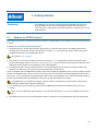
What is an RTOS Project?
This chapter first discusses in detail the files that are involved in an RTOS project. In the remaining sections an example project
is created.
The basic ideas of an RTOS project are listed below:
1. An RTOS project is a normal" Altium Designer project where you must add a file written in the OSEK Implementation
Language (OIL) to the project members. This file has the extension .oil and contains the specific details of the system
configuration. We refer to it as the application OIL file.
See Chapter 3, OIL Language
2. One and only one of the project members can have the extension .oil. The application OIL file first includes a target
specific implementation OIL file ( #include <osek\osek.oil> ) which is delivered with the product, followed by a user
defined part with all details for the configuration of your RTOS application.
3. By adding an OIL file to the list of project members, an extra project dependency is created in the project makefile. The
makefile now contains the rules to generate a special RTOS library from the OIL file.
In fact, the makefile calls the TASKING OIL Compiler (TOC) which compiles the application OIL file. The TOC compiler outputs a
number of configurational files, written in C source code. These files are used to build a dedicated RTOS library with the same
name as the .oil file. This library is then linked together with the rest of the application. The compiler and assembly options of
the project prevail while building the RTOS library (only some compiler optimizations may change).
The RTOS library is only rebuilt upon changes in the OIL file since it constitutes its only dependency. Changes in the
application software will not affect the RTOS library.
4. In your application source code files you must include the OSEK/VDX standard OS and COM interfaces (osek.h) to
compile.
When you use the Notification Flag mechanism, you must also include the file flag.h in your application source code
files.
5. The RTOS system services used in the application software are extracted from the RTOS library during the linking phase.
2−1
TSK51x / TSK52x RTOS
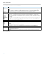
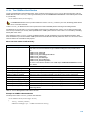
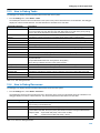
The following table lists the files involved in an RTOS project:
Extension
Description
Application source files
*.c / *.h / *.asm
C source files, header include files and optional hand coded assembly files are used to write the application
code.
These files must be members of your (Altium Designer) project and are used to build application objects.
mytypes.h
You need to write mytypes.h when using messages with non basic CDATATYPE attributes.
The application OIL file and the configurational files
user.oil
You must write exactly one application OIL file to configure the RTOS library.
It is the only .oil member of the project and contains the input for the TASKING OIL Compiler (TOC).
g_conf.c
g_conf.h
g_conf_types.h
g_isrframe.c
flag.h
orti.txt
These configurational files are intermediate files (ANSI C) generated by the TOC compiler after processing
the OIL file.
The files g_* are compiled together with the RTOS source files to build the RTOS library of the project. The
file ’flag.h’ is an extra interface for the application software. The file ’orti.txt’ is the runtime debug interface.
They are rebuilt when you change your OIL file.
RTOS source files
c_*.c
c_*.h
t_*.c
t_*.h
The source code files of the RTOS are located in
osek.h
The RTOS application interface osek.h is located in
$(PRODDIR)\c51\include\osek and constitutes the only interface for your code as an RTOS user.
$(PRODDIR)\c51\osek\
They are used by all the RTOS projects to build their RTOS libraries. They should never be removed or
modified.
Implementation OIL file
osek.oil
The implementation OIL file, which is located in $(PRODDIR)\c51\include\osek , must be included from the
OIL files of all RTOS applications.
It imposes how and what can be configured in this current RTOS release. It should never be removed or
modified.
Table 2−1: Project files
2−2
Getting Started
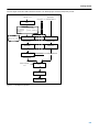
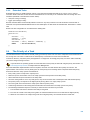
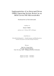
The next figure shows the relation between the files in an RTOS project and the development process.
OIL file .oil
Application
(mytypes.h) C source files .c
TASKING OIL compiler
toc
Configurational files
g_conf.c g_isrframe.c
g_conf.h g_conf_types.h
flag.h
RTOS files
c_*.c t_*.c
c_*.h t_*.h
C compiler
C compiler
assembly files
assembly files
assembler
assembler
relocatable object files
relocatable object files
archiver
RTOS library
linker script file
.lsl
linker
absolute object file
debugger
execution
environment
Figure 2−1: Development process
2−3
TSK51x / TSK52x RTOS
2.2
The Design Environment "Altium Designer"
Design Environment
Altium Designer is a Windows application that facilitates working with the tools in the toolset and also offers project management
and an integrated editor.
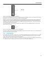
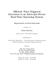
Altium Designer has three main functions: Edit / Project management, Build and Debug. The figure below shows how these
main functionalities relate to each other and how the RTOS system is integrated.
With Altium Designer you can write, compile, assemble, link, locate and finally debug RTOS applications.
Altium Designer
toolset selection
editor
project management
tool options
EDIT
makefile
make
compiler
assembler
linker
locator
BUILD
absolute file
debugger
DEBUG
Figure 2−2: Altium RTOS integrated in Altium Designer
In the Edit part you make all your changes:
•
•
•
•
Create and maintain a project and add a file user.oil to it
Edit the source files in a project
Edit the user.oil file
Set the options for each tool in the toolset
In the Build part you build your files:
• A makefile (created by the Edit part) is used to invoke the needed toolset components, resulting in an absolute object file.
The makefile rebuilds the RTOS library if the OIL file has changed.
In the Debug part you can debug your project:
• Call the TASKING debugger with the generated absolute object file. The debugger uses a special ORTI file (OSEK Run−time
Interface) to retrieve information. This file is automatically generated by the TOC compiler
The next sections will guide you step−by−step through the most important steps of building a simple RTOS application.
2−4
Getting Started
2.3
Create a new Project Space for the MYRTOS Project
Before you create your own RTOS application you need to create an embedded software project.
Create a new embedded software project
1. Start Altium Designer.
Altium Designer opens.
2. Click on the Go to Home page button on the toolbar:
Look for the Pick a task section on your screen.
3. From the Pick a task section, select Embedded Software Development.
4. Click on New Blank Embedded Software Project
The Projects panel opens. The new project file "Embedded Project1.PrjEmb" is shown.
No documents are added to the project yet.
Now save your project. You are free to choose a name and a location for the project but you can also follow this example:
5. From the File menu, select Save Project As...
The Save [Embedded Project1.PrjEmb] As... dialog appears.
−
In this dialog, browse to the folder <Altium Designer installation folder>\Examples\.
−
Create a new folder with the name firstrtos.
−
Browse to this folder.
−
Enter the file name for your project: myrtos.PrjEmb and make sure it is saved as type Embedded Software Project
(*.PrjEmb).
6. Click on the Save button.
2−5
TSK51x / TSK52x RTOS
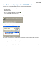
Add new files to the project
Now you can add files you want to be part of your project. You can either add existing files, or create and add new files. In this
example, two new files are needed: main.c and myrtos.oil:
7. In the Projects panel, right−click on your project myrtos.PrjEmb and select Add New to Project » C File.
A new empty file with the name Source1.C is added to your project and opened.
8. From the File menu, select Save As...
The Save [Source1.C] As... dialog appears. Save your file as main.c.
9. In the Projects panel, right−click on your project myrtos.PrjEmb and select Add New to Project » Text Document.
A new empty file with the name Doc1.Txt is added to your project and opened.
10. From the File menu, select Save As...
The Save [Doc1.Txt] As... dialog appears. Save your file as myrtos.oil.
The new project is now ready to be edited.
Altium Designer automatically creates a makefile for the project (in this case myrtos.mak.). This file contains the rules to
build your application. Altium Designer updates the makefile every time you modify your project settings.
Note that because Altium Designer detected the presence of an .oil file, the makefile contains rules to generate also
the RTOS library from the file myrtos.oil. You can check this for yourself by opening the file myrtos.mak.
2−6
Getting Started
2.4
Edit the Application Files
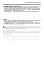
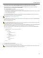
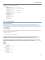
In order to get a working rtos project, you must edit main.c and myrtos.oil. It is not necessary to pay attention to the exact
contents of the files at this moment.
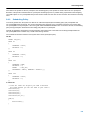
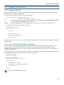
Edit the user source code
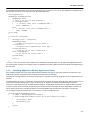
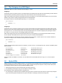
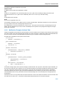
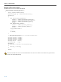
1. As an example, type the following C source in the main.c document window:
#include <osek\osek.h>
DeclareTask(task0);
DeclareTask(task1);
DeclareTask(task2);
DeclareEvent(E1);
DeclareEvent(E2);
DeclareAppMode(AP1);
int main(int argc)
{
(void)argc;
StartOS(AP1);
return 1;
}
TASK (task0)
{
EventMaskType event;
ActivateTask(task1);
while(1)
{
WaitEvent(E1 | E2);
GetEvent(task0,&event);
ClearEvent(event);
if (event & E1)
{
ActivateTask(task2);
}
else if (event & E2)
{
ActivateTask(task1);
}
}
}
TASK (task1)
{
SetEvent(task0,E1);
TerminateTask();
}
TASK (task2)
{
SetEvent(task0,E2);
TerminateTask();
}
2. Click on the Save Active Document <Ctrl+S> button to save this file.
2−7
TSK51x / TSK52x RTOS
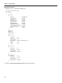
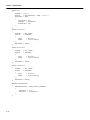
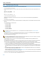
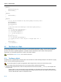
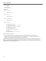
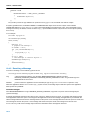
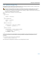
Edit the user OIL file
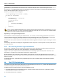
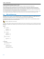
1. Edit the myrtos.oil file with the following text:
#include <osek\osek.oil>
CPU myRTOS
{
OS StdOS
{
STATUS
STARTUPHOOK
ERRORHOOK
SHUTDOWNHOOK
PRETASKHOOK
POSTTASKHOOK
USEGETSERVICEID
USEPARAMETERACCESS
USERESSCHEDULER
ORTI
};
=
=
=
=
=
=
=
=
=
=
EXTENDED;
FALSE;
FALSE;
FALSE;
FALSE;
FALSE;
FALSE;
FALSE;
FALSE;
TRUE;
EVENT E1;
EVENT E2;
APPMODE AP1;
TASK task0
{
PRIORITY
SCHEDULE
ACTIVATION
AUTOSTART
EVENT
EVENT
};
TASK task1
{
PRIORITY
SCHEDULE
ACTIVATION
AUTOSTART
};
TASK task2
{
PRIORITY
SCHEDULE
ACTIVATION
AUTOSTART
};
=
=
=
=
=
=
5;
FULL;
1;
TRUE {APPMODE=AP1;};
E1;
E2;
=
=
=
=
5;
FULL;
1;
FALSE;
=
=
=
=
5;
FULL;
1;
FALSE;
};
2. Click on the Save Active Document <Ctrl+S> button to save this file.
2−8
Getting Started
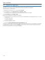
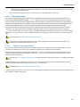
2.5
Set the Project Options
The next step is to select a target processor and specify the options for the different parts of the toolset, such as the C compiler,
assembler, linker and debugger.
1. From the Project menu, select Project Options...
The Project Options dialog appears. Here you can specify options that are valid for the entire project. You can overrule the
project options for the currently active file in the Current File Options... entry of the Project menu.
2. From the the Device list at the top−right of the page, select Altium » TSK51 » TSK51A.
3. Expand the C Compiler entry and select Memory Model.
• For the compiler memory model, select Large: variables in XDATA.
• Enable the option Allow reentrant functions.
4. Expand the Linker entry and select Stack/Heap.
• Enable the option Expand system stack size if space left.
For other pages you can make your own changes. If you have made all changes click OK.
The Cancel button closes the dialog without saving your changes. With the Set To Installation Defaults button you can
restore the default project options (for all pages).
2.6
Build Your Application
If you have modified and saved the project files, you can actually build your first RTOS application. This results in an absolute
object file which is ready to be debugged. You can build this project with default project options.
Build your Application
To build the currently active project:
• Right−click on your project myrtos.PrjEmb and select Compile Embedded Project myrtos.PrjEmb.
The OIL file is compiled and the RTOS library is built. All files together are compiled, assembled, linked and located. The
resulting file is myrtos.abs.
After you application has been built, you can check the following for yourself:
• in your project folder, a dedicated folder with the name myrtos.rtos has been created
• the TOC tool has placed the generational files g_conf.c, g_isrframe.c, g_conf_types.h and g_conf.h in this
directory
• the TOC tool has placed the configuration files orti.txt and flag.h in the project folder
• a library osek.lib has been created in the folder myrtos.rtos and it has been copied to your project folder with the
name myrtos.lib.
You can compare the contents of this directory to the files shown in figure 2−1.
2−9
TSK51x / TSK52x RTOS
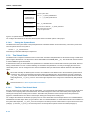
2.7
Debug Your Application
The application myrtos.abs is the final result, ready for execution and/or debugging. Since the RTOS environmennt supports
ORTI files, you can easily gain access to RTOS information during the simulation of your application.
Make sure that main.c is the active file.
1. Right−click on your project myrtos.PrjEmb and select Simulate.
2. From the View menu, select Workspace Panels » Embedded » RTOS
The RTOS panel opens. In this panel you can easily obtain RTOS information. For example:
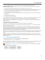
3. From the Debug menu, select RTOS » Tasks.
Before running the application, it is helpful to put breakpoints:
4. To toggle breakpoints on or off, click just in front of a source line. Set breakpoints at the following lines in the main.c source:
• WaitEvent(E1 | E2);
• SetEvent(task0,E1);
• SetEvent(task0,E2);
5. To execute the application, press F9
Or: click on the Run the embedded program being debugged button:
Every time you press the F9 key, the program runs untill the next breakpoint. Note the effect on the information in the tasks part
of the RTOS panel: for example, in the column NORUNS (number of runs), you will see how often a particular task has been
executed. The count updates every time you press the F9 key.
2−10
3 The OSEK/VDX Implementation Language
(OIL)
Summary
3.1
This chapter describes how you can configure your application with a file written in
OIL (OSEK Implementation Language) language (which needs to be added to the
project as a project member). The chapter ends with a working example of an OIL
file.
Why an OIL Language
Purpose of the OIL language
The OSEK/VDX Implementation Language (OIL) language is used to configure the RTOS library. An OIL configuration file
contains the definition of the application. The usage of OIL to configure OSEK/VDX systems enhances the portability of RTOS
applications among different target processors.
Hand−coded or generated
Depending on the OSEK/VDX implementation you must either write the OIL file manually or you can use a graphical user
interface which helps you create the OIL file.
3.2
What are the OIL System Objects?
Every version of OIL language defines syntactically and semantically a set of OIL system objects. These objects are defined in
the OSEK standard. One of the system objects is CPU. This serves as a container for all other objects. Objects are defined by
their attributes.
Refer to http://portal.osek−vdx.org/files/pdf/specs/oil25.pdf for detailed information.
3.2.1
Standard and Non−Standard Attributes
Every OIL system object has attributes that can hold values. According to the OIL standard, each object has at least a minimum
mandatory set of attributes, called the standard attributes. Besides the standard attributes, an OSEK/VDX implementation may
define additional attributes (non−standard attributes) for any OIL system object.
To configure a system for an specific OSEK/VDX implementation you need to instantiate and/or define OIL objects and assign
values to their attributes.
An OSEK/VDX implementation can limit the given set of values for object attributes.
Since the non−standard attributes are OSEK/VDX implementation specific they are not portable. However, there are two
reasons to justify non−standard attributes:
• they can address platform specific features
• they can provide extra configuration possibilities for a certain target
3−1
TSK51x / TSK52x RTOS
3.2.2
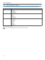
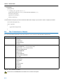
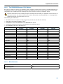
Overview of System Objects and Attributes
The next table shows the list of system objects with their standard attributes as defined by OIL2.5 and the non−standard
attributes for the TSK51x/TSK52x. The non−standard attributes are marked italic.
Because the Altium RTOS supports only internal communication, the subset of objects and standard attributes differs
from the OIL2.5 definition:
•
•
•
•
MESSAGE object
(Altium RTOS differs)
NETWORK MESSAGE object
(not present in Altium RTOS)
COM object
(Altium RTOS differs)
IPDU object
(not present in Altium RTOS)
In addition to the attributes listed in the table below, there are a number of non−standard attributes which are not included
in this table. These extra attributes all start with the keyword WITH_AUTO and take AUTO as their default value (you can
search for them in the file osek.oil). This subset of attributes can be considered as internals of the implementation and
are not user configurable. Instead, the TOC tool initializes them.
OIL system
object
Description
CPU
The CPU on which the application runs under the RTOS control.
Standard Attributes
Non Standard Attributes
Container of all the other objects.
OS
The OS that runs on the CPU.
All system objects are controlled by OS.
STATUS
STARTUPHOOK
ERRORHOOK
SHUTDOWNHOOK
PRETASKHOOK
POSTTASKHOOK
USEGETSERVICEID
USEPARAMETERACCESS
USERESSCHEDULER
LONGMSG
MULTISTART
ORTI
STACKMONITOR
USERTOSTIMER
CORE
EXTDATASIZE
SMAINSTACK
VISRSTACK
APPMODE
Defines different modes of operation for the application.
ISR
Interrupt service routines supported by OS.
CATEGORY
RESOURCE [ ]
MESSAGE [ ]
LEVEL
ENBIT
RESOURCE
The resource that can be occupied by a task.
RESOURCEPROPERTY
TASK
The task handled by the OS.
PRIORITY
SCHEDULE
ACTIVATION
AUTOSTART
RESOURCE [ ]
EVENT [ ]
MESSAGE [ ]
SSTACK
VSTACK
COUNTER
The counter represents hardware/software tick source for alarms.
MAXALLOWEDVALUE
TICKSPERBASE
MINCYCLE
EVENT
The event on which tasks may react.
MASK
3−2
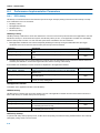
The OSEK/VDX Implementation Language (OIL)
OIL system
object
Description
Standard Attributes
Non Standard Attributes
ALARM
The alarm is based on a counter and can either activate a task or set
an event or activate an alarm−callback routine.
COUNTER
ACTION
AUTOSTART
MESSAGE
The message is defined in OSEK COM and defines a mechanism for
data exchange between different entities (tasks or ISRs)
MESSAGEPROPERTY
NOTIFICATION
COM
The communication subsystem. The COM object has standard
attributes to define general properties for the interaction layer.
COMERRORHOOK
COMERRORGETSERVICEID
COMUSEPARAMETERACCESS
COMSTARTCOMEXTENSION
COMAPPMODE [ ]
COMSTATUS
NM
The network management subsystem.
Table 3−1: OIL objects and their standard and non−standard attributes
3.2.3
Non−Standard Attributes for the TSK51x/TSK52x
This section describes the non−standard attributes, which are specific for the TSK51x/TSK52x.
Please refer to the OSEK/VDX OIL documentation for the semantics of all standard attributes.
OS object
CORE
The CORE attribute specifies the Processor Definition of the project. The type of this attribute is ENUM and has one of the
following values:
TSK51A, TSK52A, TSK52B
The default value is TSK51A.
EXTDATASIZE
The EXTDATASIZE attribute indicates the maximum size (in bytes) of the extended data section. The extended data section
resides in the internal data area and it is used for extra register allocation. You define the maximum size of this area with the
compiler option −x (default is 4 bytes). Since this area is shared by all tasks, the RTOS needs to save/restore it during context
switch (it is part of the context of the task). The type of this attribute us UINT32 and the default value is 4 bytes.
You need to update this attribute everytime you change the option −x of the compiler.
LONGMSG
The LONGMSG boolean attribute determines whether Category 2 ISRS are suspended during the copy of messages from the
RTOS buffers to the application or vise versa. If set to TRUE, the RTOS expects long messages, so the interrupts will not be
suspended. This is at the cost of extra handling. The default value is FALSE.
MULTISTART
The MULTISTART boolean attribute specifies whether the system is allowed to start the RTOS more than once (undergoing
application resets via the usage of ShutdownOS()). It has a default value of FALSE.
See section 4.5, The Shut−Down Process in chapter Startup Process.
ORTI
With the ORTI attribute you can request the RTOS to provide the debugger with as much RTOS debug information as possible
via the ORTI interface. If you set this attribute to TRUE, the run−time performance suffers from extra overhead that should be
avoided in final production. (If you set this attribute to FALSE, not all debug information will be available to the debugger). The
type of ORTI is BOOLEAN. It has a default value of FALSE.
3−3
TSK51x / TSK52x RTOS
SMAINSTACK
The SMAINSTACK attribute specifies the maximum usage (in bytes) of the system stack before the application starts the RTOS
with the system service StartOS. The RTOS allocates a dedicated buffer to save these bytes. You can easily find the best value
by comparing the value of the system stack pointer after main and before the call to StartOS.
The type of this attribute is UINT32. It has a default value of 8.
STACKMONITOR
With the STACKMONITOR attribute you can request the RTOS to monitor continuously possible stack overflows for you.
Although expensive in run−time performance, the RTOS will inform you as soon as possible with the precise cause of the stack
overflow. The default value is FALSE.
See Appendix B, Stack Overflow, for an extensive description of this attribute.
USERTOSTIMER
The USERTOSTIMER is a parametrized boolean attribute which determines whether ALARM OIL objects based on the system
counter have been configured in the system.
If set to TRUE, the RTOS provides the interrupt framework for the timer unit and the application provides its initialization. In this
case, you must set the parameter RTOSTIMERLEVEL with the entry of the timer unit in the Interrupt Vector Table. The type of
RTOSTIMERLEVEL is UINT32. It has no default value.
The default value for USERTOSTIMER is FALSE.
VISRSTACK
The RTOS allocates a dedicated buffer for the run−time virtual stacks of the interrupts. The VISRSTACK attribute specifies the
size of this buffer (in bytes). You should consider the worst case scenario (maximum nested number) and the RTOS contribution
(see Appendix A, Implementation Parameters).
The type of this attribute is UINT32. The default value is 100 bytes.
ISR object
ENBIT
The ENBIT attribute specifies the SFR register bit that enables/disables the ISR. The type of this attribute is STRING. It has no
default value.
Check the .sfr files in $(PRODDIR)\c51\include to find the appropiate .sfr file name.
LEVEL
The LEVEL attrribute specifies the entry in the Vector Interrupt Table.
The RTOS source code uses this value as argument for the __interrupt function qualifier. The type of this attribute is
UINT32. It has no default value.
TASK object
SSTACK
The SSTACK attribute specifies the contribution of the task to the system stack (in bytes). The type of this attribute is UINT32.
The default value is 30.
Section 5.7.2, The System Stack, in Chapter Task Management.
VSTACK
The VSTACK attribute specifies the contribution of the task to the virtual stack (in bytes). The type of this attribute is UINT32.
The default value is 60.
Section 5.7.3, The Virtual Stack, in Chapter Task Management.
3−4
The OSEK/VDX Implementation Language (OIL)
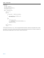
3.3
The Structure of an OIL File
The complete OIL configuration consists of two parts (files):
• Implementation Part: Definition of the OIL system objects with their standard and implementation specific features (the
standard and non−standard attributes). The implementation part is delivered with the product as a separate system OIL file
which you must include before the application part. The file is named osek.oil and should never be modified. It is located
in the OSEK directory of the general include directory of the toolset.
• Application Part: Defines the structure of the application located on the particular CPU. For every RTOS application, you
must write an application part (or: user OIL file). In this file you instantiate objects that are defined in the implementation part.
The user OIL file must therefore include the system OIL file, like you include header files in a C source.
The Application Part is slaved to the Implementation Part. In object oriented terminology we would say that the Implementation
Part contains the class definitions" of all OIL objects for all projects. In a specific project the classes" are instantiated in the
Application Part of the OIL configuration file.
For example: In the Implementation Part an OIL object TASK exists which defines PRIORITY as one of its attributes. In the
Application Part you must now instantiate classes of the kind TASK and give values to their PRIORITY attributes.
Restrictions
• At least one CPU object must be defined in the Application Part and it must be defined first since it is the container object for
all other objects defined in the configuration. All the other objects are defined inside the CPU object.
• One and only one OS object can reside in each CPU container since it defines global characteristics for the system (CPU
speed, RTOS hardware resources etc. are typical). OSEK/VDX implementations usually add many non−standard attributes
in this object.
• One and only one COM object can reside in each CPU container.
With an OIL generator tool, a friendly GUI interface will guide you in the process of configuring the Application Part of the
OIL file and it will output a syntactically correct OIL configuration file for you. Without such a tool you must hand−code the
Application Part (taking care of its grammatical correctness) of the OIL file.
3.3.1
Implementation Part
The Implementation part of the OIL file is delivered with the product in the file osek.oil. You can find this file in the general
include directory of the toolset. This file, the Implementation OIL file, represents a mandatory interface for the Application OIL
part in the OIL file of all projects.
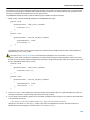
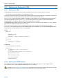
3.3.2
Application Part
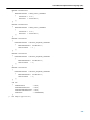
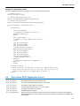
The Application OIL part contains all instances of OIL objects for a given application. Below you will find an example of how an
OIL file may look like.
You must select proper names for the OIL objects since they become variables with global scope (and with type ObjectType).
For instance, if you define in the OIL file an EVENT object download, you cannot define a function with such a name in your
source code (the least you can expect is link errors).
3−5
TSK51x / TSK52x RTOS
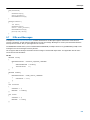
#include <osek\osek.oil>
CPU Sample_CPU1
{
OS StdOS
{
STATUS
STARTUPHOOK
ERRORHOOK
SHUTDOWNHOOK
PRETASKHOOK
POSTTASKHOOK
USEGETSERVICEID
USEPARAMETERACCESS
USERESSCHEDULER
MULTISTART
STACKMONITOR
ORTI
};
=
=
=
=
=
=
=
=
=
=
=
=
EXTENDED;
TRUE;
TRUE;
TRUE;
TRUE;
TRUE;
TRUE;
TRUE;
TRUE;
TRUE;
TRUE;
TRUE;
APPMODE AUTOSTART {};
APPMODE NONAUTOSTART {};
EVENT intervaldelay;
RESOURCE sem_printf { RESOURCEPROPERTY = STANDARD; };
RESOURCE sem_out
{ RESOURCEPROPERTY = STANDARD; };
TASK init
{
PRIORITY
= 7;
SCHEDULE
= NON;
ACTIVATION = 1;
RESOURCE
= sem_out;
AUTOSTART = TRUE
{
APPMODE=AUTOSTART;
APPMODE=NONAUTOSTART;
};
};
TASK monitor
{
PRIORITY
SCHEDULE
ACTIVATION
AUTOSTART
MESSAGE
MESSAGE
MESSAGE
MESSAGE
};
=
=
=
=
=
=
=
=
9;
FULL;
1;
FALSE;
sendHandler1;
sendHandler2;
sendHandler3;
recCommand;
MESSAGE sendCommand
{
MESSAGEPROPERTY = SEND_STATIC_INTERNAL
{
CDATATYPE = "myCommand";
RECEIVER = recCommand;
};
};
3−6
The OSEK/VDX Implementation Language (OIL)
MESSAGE recCommand
{
MESSAGEPROPERTY = RECEIVE_QUEUED_INTERNAL
{
SENDINGMESSAGE = sendCommand;
QUEUESIZE
= 5;
};
NOTIFICATION
= ACTIVATETASK
{
TASK = monitor;
};
};
TASK bounce1
{
PRIORITY
SCHEDULE
ACTIVATION
AUTOSTART
EVENT
MESSAGE
RESOURCE
};
TASK bounce2
{
PRIORITY
SCHEDULE
ACTIVATION
AUTOSTART
EVENT
MESSAGE
RESOURCE
};
TASK bounce3
{
PRIORITY
SCHEDULE
ACTIVATION
AUTOSTART
EVENT
MESSAGE
RESOURCE
};
TASK trsi
{
PRIORITY
SCHEDULE
ACTIVATION
AUTOSTART
RESOURCE
};
=
=
=
=
=
=
=
5;
FULL;
1;
TRUE { APPMODE=AUTOSTART; };
intervaldelay;
recHandler1;
sem_printf;
=
=
=
=
=
=
=
5;
FULL;
1;
TRUE { APPMODE=AUTOSTART; };
intervaldelay;
recHandler2;
sem_printf;
=
=
=
=
=
=
=
5;
FULL;
1;
TRUE { APPMODE=AUTOSTART; };
intervaldelay;
recHandler3;
sem_printf;
=
=
=
=
=
11;
FULL;
1;
FALSE;
sem_out;
COUNTER crsi
{
MAXALLOWEDVALUE = 500;
TICKSPERBASE
= 1;
MINCYCLE
= 3;
};
3−7
TSK51x / TSK52x RTOS
ALARM arsi
{
COUNTER
= crsi;
ACTION
= ACTIVATETASK { TASK = trsi; };
AUTOSTART = TRUE
{
CYCLETIME = 200;
APPMODE
= AUTOSTART;
ALARMTIME = 200;
};
};
ALARM ainterval1
{
COUNTER
= SYS_TIMER;
ACTION
= SETEVENT
{
TASK
= bounce1;
EVENT
= intervaldelay;
};
AUTOSTART = FALSE;
};
ALARM ainterval2
{
COUNTER
= SYS_TIMER;
ACTION
= SETEVENT
{
TASK
= bounce2;
EVENT
= intervaldelay;
};
AUTOSTART = FALSE;
};
ALARM ainterval3
{
COUNTER
= SYS_TIMER;
ACTION
= SETEVENT
{
TASK
= bounce3;
EVENT
= intervaldelay;
};
AUTOSTART = FALSE;
};
MESSAGE sendHandler1
{
MESSAGEPROPERTY = SEND_STATIC_INTERNAL
{
CDATATYPE = "int";
RECEIVER = recHandler1;
};
};
3−8
The OSEK/VDX Implementation Language (OIL)
MESSAGE sendHandler2
{
MESSAGEPROPERTY = SEND_STATIC_INTERNAL
{
CDATATYPE = "int";
RECEIVER = recHandler2;
};
};
MESSAGE sendHandler3
{
MESSAGEPROPERTY = SEND_STATIC_INTERNAL
{
CDATATYPE = "int";
RECEIVER = recHandler3;
};
};
MESSAGE recHandler1
{
MESSAGEPROPERTY = RECEIVE_UNQUEUED_INTERNAL
{
SENDINGMESSAGE = sendHandler1;
INITIALVALUE
= 3 ;
};
};
MESSAGE recHandler2
{
MESSAGEPROPERTY = RECEIVE_UNQUEUED_INTERNAL
{
SENDINGMESSAGE = sendHandler2;
INITIALVALUE
= 3;
};
};
MESSAGE recHandler3
{
MESSAGEPROPERTY = RECEIVE_UNQUEUED_INTERNAL
{
SENDINGMESSAGE = sendHandler3;
INITIALVALUE
= 3;
};
};
COM Com
{
COMERRORHOOK
COMUSEGETSERVICEID
COMUSEPARAMETERACCESS
COMSTARTCOMEXTENSION
COMSTATUS
};
=
=
=
=
=
TRUE;
TRUE;
TRUE;
TRUE;
COMEXTENDED;
}: "CPU Sample application";
3−9
TSK51x / TSK52x RTOS
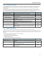
3.4
Preprocessor Commands
The OIL preprocessor allows the following preprocessor commands:
•
•
•
•
•
•
•
#include "file" or #include <file>
(Define without macro replacement)
#define A
#ifdef A
#ifndef A
#else
#endif
#usedef A
#use A
(Define with macro replacement)
A_REPL
It is highly recommended to divide the functionality of the OIL file into separated files. The syntax is the same as in
ISO/ANSI−C.
The OIL preprocessor accepts C++ −style comments (/* */ and //). C++ rules apply.
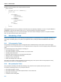
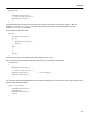
Examples
In file app1.oil:
#define APP1
In file conf.oil
#include "appl.oil"
#ifdef APP1
#usedef taskconf
PRIORITY
ACTIVATION
= 6; \
= 2;
PRIORITY
ACTIVATION
= 7; \
= 1;
#endif
#ifdef APP2
#usedef taskconf
#endif
In file myoil.oil:
#include "conf.oil"
TASK myTask
{
#use
taskconf
SCHEDULE = FULL;
AUTOSTART = FALSE;
...
}
3−10
4 The Startup Process
Summary
4.1
This chapter explains what happens inside the system from application reset until the
first application task is scheduled and describes how you can interfere with the
start−up process by customizing certain Hook Routines.
Introduction
This chapter details the various phases the system undergoes from CPU reset until the first application task is scheduled. You
can intervene in this process via the Hook Routines and the Application Modes.
Please refer to the OSEK/VDX OIL documentation for details about the Hook Routines and Application Modes.
The startup process includes the following phases:
1. System boot
2. C entry point main()
3. StartOS
4. RTOS initialization phase: Hook Routines
After the startup process the first task is scheduled.
4.2
System Boot
When the processor first starts up, it always looks at the same place in the system ROM memory area for the start of the system
boot program. The boot code runs sequentially until it reaches the point where it jumps to the label main. This code runs, of
course, in the absence of the operating system.
In general, embedded systems differ so much from each other that the boot code tends to be almost unique for each system.
You can create the system boot in two ways:
1. Reuse the standard startup code provided by the toolset and enhance it (if necessary) to suit the specific needs of your
hardware. The standard startup code merely contains what is necessary to get the system running. It is easy configurable
via Project Options in the Project menu.
2. You may decide to create the system boot code if some board specific actions need to be taken at a very early stage. Some
of the most common actions are:
•
•
•
•
•
•
Initialization of critical microprocessor registers (including standard pointers like the stack pointer).
Initialization of specific peripheral registers for your unique hardware design.
Initialization of all static variables (using the delivered _init routine).
Distinguish the source of processor reset (hard or soft reset, power−on reset, watchdog, ...).
Addition of some power−on tests.
Call the label main() to start the application.
4−1
TSK51x / TSK52x RTOS
4.3
The main() Module
At the moment of entering main() only minimal controller initialization has occurred. At this point the application can run extra
(application−specific) initialization routines before the RTOS starts. This code cannot call an RTOS system service.
The OSEK/VDX standard defines a service to start the operating system:
void StartOS(AppModeType);
4.3.1
What are Application Modes?
Application Modes allow you (as a matter of speaking) to have multiple" applications in one single image. Application Modes
allow application images to structure the software running in the processor depending on external conditions. These conditions
must be tested by the application software upon system reset. The difference in functionality between applications that start in
different modes is determined by:
• Which tasks and which alarms automatically start after the RTOS initialization.
• Mode−specific code (the mode can be detected at run time by using the system service GetActiveApplicationMode).
You define (and set all these dependencies) in the OIL file of the project. The OSEK/VDX does not set a limit for the number of
Application Mode objects. See Appendix A, Implementation Paramaters, for the maximum number of application modes in this
implementation.
4.3.2
Defining Application Modes
The application modes are strongly related to the decissions you take at system architecture level. The following example of an
ATM (Automated Teller Machine) illustrates this dependency.
Let us assume an ATM which must meet the following system requirement: The ATM software shall be upgraded locally at high
speed and being service affecting".
How could we implement a solution for such a scenario? The software can be designed in such a way, it has two mutually
exclusive modes: a download mode and mode for normal operation. In this example, an external pin must be read before the
RTOS starts (after reset) to distinguish between the modes: if the pin is not asserted, the image starts in ’normal mode’, if
asserted the image starts in ’download mode’.
The download process takes place locally: to download a new image, an operator must go to the ATM location. The operator
must, in order, (1) open the ATM box, (2) assert the pin, (3) reset the machine to start it in download mode, (4) download the
image from a notebook, (5) deassert the pin, (6) reset the machine to start it in normal operation mode, (7) close the ATM box.
Obviously while downloading a new image, the ATM is out of service.
In the OIL file you would define two APPMODE objects like:
APPMODE NORMAL {};
APPMODE DOWNLOAD {};
In NORMAL operation mode the ATM machine is ready to address customer queries. A task is started that offers, for example, a
tactile−graphical interface waiting for customer queries, another task maintains a link with a bank database to update the
customer latest data a third task interfaces with the paper money repository.
In DOWNLOAD operation mode, the ATM machine starts a task to process download messages over a fast serial line. Another
task flashes the image to the target read only memory. The system is entirely dedicated to download purposes.
Code example
OIL file
You define application modes in the OIL file like:
APPMODE NORMAL {};
APPMODE DOWNLOAD {};
C source file
In the application source code, like with all other OIL objects, you need to declare the application mode before using it:
4−2
The Startup Process
The example assumes that the system boot code passes the type of reset as resetparam. The application is designed so that
the execution flow returns to the boot code when the RTOS shuts down.
DeclareAppMode(mode);
AppModeType GetAppMode(void)
{
AppModeType mode;
/* check if the pin has been asserted */
if (PinIsAsserted())
{
/* ’StartOS’ shall start in DOWNLOAD mode */
mode = DOWNLOAD; }
else
{
/* ’StartOS’ shall start in NORMAL mode */
mode = NORMAL;
}
return mode;
}
int main(int resetparam)
{
ResetType reset = resetparam;
AppModeType mode;
/* common initialization for all
InitInCLevel();
/* different action depending on
InitSystem(reset);
/* find out the run time current
mode = GetAppMode();
/* start the OS for current mode
StartOS(mode);
...
return 1;
}
modes */
reset type */
mode */
*/
StartOS() is the one and only method defined by the OSEK/VDX standard in which you can define the Application Mode for
the current system environment. To change modes, the application must first shutdown and then the RTOS must restart using a
the new mode.
4.3.3
Changing Application Modes: Application Reset.
Since sending operators across the whole ATM network is inefficient and costly, a new system requirement could arise: The
ATM software shall be upgraded remotely at high speed and being service affecting".
Identically two mutually exclusive modes keep coexisting but no operator is needed (on location). How do we implement such a
solution?
The ATM software can receive a command to change its mode (the system shuts down and starts again with the other mode). In
order to download the following steps, in order, are necessary: an operator in the bank headquarters issues remotely a
command to enter download mode, the ATM software undergoes an application reset and starts up again the link in download
mode, the operator sends download commands over the link and when the new image has been downloaded, a command to
enter normal mode is issued. The ATM undergoes a second application reset and starts the new image in normal mode.
You should then implement a function like ChangeMode() in order to change the mode:
void ChangeMode(AppModeType mode)
{
if (mode != GetActiveApplicationMode() )
/* GetActiveApplicationMode returns the current application mode */
{
CurrentMode = mode;
ShutdownOS(E_OK);
}
return;
}
4−3
TSK51x / TSK52x RTOS
In NORMAL mode, the application calls this routine when it has been signaled remotely to start downloading an image. First a
global variable is updated to indicate the desired next mode and then the system shuts down with the system service
ShutdownOS(). The implementation makes sure that after the execution of this system service the system effectively returns
from the API that started the RTOS, thus from StartOS().
The main() code should now be changed to:
static AppModeType CurrentMode = NORMAL;
int main(int resetparam)
{
ResetType reset = resetparam;
InitInCLevel();
InitSystem(reset);
while (1)
{
StartOS(CurrentMode);
}
return 1;
}
The non−standard attribute MULTISTART of the OS object must be defined as TRUE in the OIL file because StartOS()
can be called more than once. Only in systems where application resets will never occur, the value of the MULTISTART
attribute can be set as FALSE. This saves code and data size.
Dependency on the System Requirements
An ATM machine could enter temporarily the download mode, out of service", without causing great disaster (at most some
customers will be bothered to try other ATMs nearby). But could a telecommunication router stop performing its normal traffic
operation because it is upgrading remotely its software? This depends strongly on the system requirements.
Let us assume then a system requirement: "The ATM software shall be upgraded remotely at low speed and being non−service
affecting".
Downloading is performed in the background, mingled with the other components, in normal operation. In such system there is
no download" mode.
4.3.4
Non−mutually Exclusive Application Modes
So far we think of application modes as performing mutually exclusive tasks. Although this describes well the general case it
should not be taken as a dogma. Let us think what happens in the following mental example.
Imagine a rack system composed of three identical boards where functionality depends on their position in the rack. If the
functionality is very different we would possibly maintain three software images.
But what happens if their functionality is almost identical? It would be then convenient to distinguish three modes (for each
position) and determine at run time which code to execute (the system service GetActiveApplicationMode will specify the current
position in the rack).
The benefits are obvious: it eases the factory programming process (only one software image) and the boards will become
interchangeable.
4.4
The RTOS Initialization
This section shows what happens inside the system from the moment that you call StartOS() until the first application task is
scheduled and explains how you can intervene in this process.
The RTOS performs the following actions during the initialization process:
1. The RTOS initializes some internal data structures on the basis of what is stated in the OIL file. In particular, it prepares
autostarting tasks and alarms to start running.
2. The RTOS hardware timer is initialized.
4−4
The Startup Process
The unit of time is the system tick (defined as the interval between two consecutive hardware clock interrupts). The
implementation parameter OSTICKDURATIONINMSCS defines the length (in milliseconds) of the system tick.
Not all applications need a system counter (only those with ALARM OIL objects based on the system counter). You
determine this with the non−standard attribute USERTOSTIMER.
When USERTOSTIMER is set to TRUE:
• The RTOS builds the framework for the system counter interrupt.
• Due to the amount of derivatives/systems it must still be you who actually initializes the hardware clock. In fact, you must
provide a definition for the Interface:
void InitRTOSTimer(void);
If the USERTOSTIMER attribute in the OIL file is set but you do not define the InitRTOSTimer routine in your source, the
linking phase fails because it encounters unresolved externals.
See section 8.2.2. The RTOS System Counter.
3. The RTOS calls the hook routine StartupHook (provided that you have assigned the value TRUE to the STARTUPHOOK
attribute of the OS object in the OIL file):
void StartupHook(void);
If the STARTUPHOOK attribute in the OIL file is set but you do not define the StartupHook routine in your source, the
linking phase fails because it encounters unresolved externals.
During the lifetime of the StartupHook routine all the system interrupts are disabled and you have only restricted access to
system services. The only available services are GetActiveApplicationMode() and ShutdownOS().
You should use this hook routine to add initialization code which strongly relies on the current selected Application Mode.
void StartupHook(void)
{
AppModeType mode = GetActiveApplicationMode();
switch (mode)
{
case NORMAL:
InitLinkBankDriver();
break;
case DOWNLOAD:
InitLinkServerDriver();
InitFlashDriver();
break;
default:
ShutdownOS(E_OK);
break;
}
return;
}
4. The RTOS enables all system interrupts
5. The RTOS executes the highest priority task ready to execute.
If you define the AUTOSTART attribute as FALSE for all TASK objects in the OIL file, the system enters directly into an
RTOS−defined idle state. The system then waits for external events.
4−5
TSK51x / TSK52x RTOS
4.5
The Shut−down Process
The OSEK/VDX standard defines a service to shut−down the operating system:
void ShutdownOS(StatusType);
1. You can directly request the ShutdownOS routine. In this case, you must define your own set of shut−down reasons: error
codes.
#define E_APP_ERROR1
#define E_APP_ERROR2
...
...
#define E_APP_ERROR192
64
65
255
(0−63 are reserved for the RTOS code)
As soon as your application encounters error N, the ShutdownOS routine must be called with E_APP_ERRORN as
parameter:
ShutdownOS(E_APP_ERRORN);
2. The ShutdownOS routine can also be reached internally by the operating system in case the RTOS encounters an internal
fatal error.
The possible RTOS error codes then are:
E_OS_SYS_ERROR
E_OS_SYS_VALUE
E_OS_SYS_UOFLW
E_OS_SYS_SOFLW
E_OS_SYS_TOFLW
E_OS_SYS_RTOFLW
E_OS_SYS_RUNLEVEL
The RTOS error codes are defined in osek.h , and described into more detail in Section 4.6, Shut−down RTOS
Application Errors.
In (the body of) ShutdownOS(), the RTOS calls the hook routine ShutdownHook, provided that you have assigned the
value TRUE to the SHUTDOWNHOOK attribute of the OS object in the OIL file.
void ShutdownHook(StatusType);
If the SHUTDOWNHOOK attribute in the OIL file is set but you do not define the ShutdownHook routine in your source,
the linking phase fails because it encounters unresolved externals.
During the lifetime of the ShutdownHook routine all system interrupts are disabled and the only available service is
GetActiveApplicationMode().
The OSEK/VDX standard allows you to define any system behavior in this routine, including not returning from the function
at all. In any case, you should always check for both application and RTOS error codes. Typical actions would be:
• If you run with a debugger, always set a breakpoint in this routine to study the nature of the possible shutdown reasons.
• In absence of a debugger, use a logging mechanism (be aware that ISR2 are temporarily disabled).
• In case a fatal error is encountered, you should force the system to shut down (or hardware reset). All RTOS errors are
(by definition) fatal and you should decide whether any of your own application errors should also be considered fatal (if
any).
• You could use the ShutdownOS() instead to force the system to undergo application software resets. You should then
set the non−standard attribute MULTISTART to true.
See also section 4.3.3, Changing Application Modes: Application Reset. The control then must be given to the application
in main() where the RTOS should be re−started again.
In case you decide to return from ShutdownHook, the RTOS cleans up all opened objects and returns from the previous call
to StartOS(). The control is given back to the application in main().
4−6
The Startup Process
Example of a Shut−down routine
The next example illustrates how a typical ShutdownOS hook routine can look like.
/* hardware reset */
extern void Reset(void);
/* handles application error N */
extern void HandlerErrorN(StatusType Error);
/* handles stack overflow */
extern void HandlerStackOverflow(StatusType Error);
void ShutdownHook (StatusType Error)
{
switch(Error)
{
case E_APP_ERRORN:
/* application handler for error N */
HandlerErrorN(Error);
break;
case E_APPL_RESET:
/* Example of "good" application reset */
break;
case E_OS_SYS_UOFLW:
case E_OS_SYS_SOFLW:
case E_OS_SYS_TOFLW:
/* Stack Overflow handler */
HandlerStackOverflow(Error);
case E_OS_SYS_ERROR:
case E_OS_SYS_VALUE:
case E_OS_SYS_RTOFLW:
case E_OS_SYS_RUNLEVEL:
/* RTOS internal fatal */
default:
/* Something undefined has happened */
Reset();
break;
}
/* return to main() */
/* After returning, the RTOS will clean up all opened objects and
return from the previous call to StartOS(). The control will be
normally given back to the application in main(). */
return;
}
4.6
Shut−down RTOS Application Errors
E_OS_SYS_ERROR
The RTOS finds himself in an undefined state.
E_OS_SYS_VALUE
The value of an RTOS variable has gone out of range.
E_OS_SYS_UOFLW
The stack of a user’s task has overflown.
E_OS_SYS_SOFLW
A system stack (interrupt stack, etc..) has overflown.
E_OS_SYS_TOFLW
A target specific stack has overflown.
E_OS_SYS_RTOFLW
A RTOS buffer has overflown.
E_OS_SYS_RUNLEVEL
System services are called from tasks, interrupt service routines, hook routines, and alarmcall
backs. Depending on the system service, there may be restrictions regarding the availability. See
the next table.
4−7
TSK51x / TSK52x RTOS
Service
Task
ISR
cat 1
ISR
cat 2
Error
Hook
Pre
Task
Hook
Post
Task
Hook
Start
up
Hook
Shut
Down
Hook
alarm−
call
back
ActiveTask
V
TerminateTask
V
V
ChainTask
V
Schedule
V
GetTaskID
V
V
V
V
V
GetTaskState
V
V
V
V
V
Disable−
AllInterrupts
V
V
V
Enable−
AllInterrupts
V
V
V
Suspend−
AllInterrupts
V
V
V
V
V
V
Resume−
AllInterrupts
V
V
V
V
V
V
Suspend−
OSInterrupts
V
V
V
V
Resume−
OSInterrupts
V
V
V
V
GetResource
V
V
ReleaseResource
V
V
SetEvent
V
V
ClearEvent
V
GetEvent
V
WaitEvent
V
GetAlarmBase
V
V
V
V
V
V
V
V
V
GetAlarm
V
V
V
V
V
SetRelAlarm
V
V
SetAbsAlarm
V
V
CancelAlarm
V
V
GetActive−
ApplicationMode
V
V
V
V
V
V
V
V
V
StartOS
ShutdownOS
Table 4−1: API service restrictions
4−8
V
V
5 Task Management
Summary
5.1
This chapter explains how the RTOS manages tasks (scheduling policies, tasks
states, ..) and describes how you can declare TASK objects in the OIL file in order to
optimize your task configuration.
What is a Task?
A task is a semi−independent program segment with a dedicated purpose. Most modern real−time applications require multiple
tasks. A task provides the framework for the execution of functions. The RTOS provides concurrent and asynchronous
execution of tasks. The scheduler organises the sequence of task execution including a mechanism which is active when no
other system or application function is active: the idle−mechanism.
ECC2 OSEK/VDX Conformance CLASS
The concept of task is obviously the most important concept in the OSEK/VDX OS standard. In the standard, a task is either
basic or extended, has a well defined static priority, is or not preemptable, can or cannot enter the waiting state, is or not the
only owner of a priority level, and so on. All possible definitions of these attributes and their interrelation define four different
conformance class levels: BCC1, BCC2, ECC1, ECC2.
This OSEK/VDX implementation is ECC2 compliant. The reason to choose this conformance class is simple: it includes all the
others (any task developed for a BCCx−level can be used in a ECCx−level and any task written for an xCC1−level can be used
in a xCC2−level). As a consequence of being ECC2 compliant:
•
•
•
•
The number of task activations can be larger than one.
The number of tasks occupying a particular priority level can be larger than one.
Basic tasks are supported.
Extended tasks are supported.
5.2
Defining a Task in the C Source
To configure a task, you must declare a specific TASK object in the user OIL file of the project and assign values to all of
its attributes. Please refer to the OSEK/VDX documentation for detailed information about all possible attributes of a task
and how to use them.
With the macro TASK you can define a task in your application. The name of the TASK object in the OIL file is passed as
parameter to the macro.
You must always end the code of a task with the system service TerminateTask or ChainTask (regardless of whether the
RTOS defines a resistant default behavior in case the task reaches a (forbidden) RET instruction). For example, to define the
task mytask:
TASK(mytask)
{
.
. code for task ’mytask’
.
TerminateTask();
}
The OSEK/VDX implementation uses this macro to encapsulate the implementation−specific formatting of the task definition
(mytask is the identity of the task and is of the type TaskType). During preprocessing, the C name of the function that
correspond to the task is created by adding the prefix ’_os_u_’ to the task name. You can then view the function with the
debugger using the mingled name: ’_os_u_mytask ’.
5−1
TSK51x / TSK52x RTOS
5.3
The States of a Task
A task goes through several different states during its lifetime. A processor can only execute one instruction at a time so, even
when several tasks are competing for the processor at the same time, only one task is actually running. The RTOS is
responsible of saving and restoring the context of the tasks when they undergo such state transitions
A task can be in one of the following states:
Task state
Description
running
The CPU is now assigned to the task and it is executing the tesk. Only one task can be in this state at any
point in time.
ready
All functional prerequisites for a transition into the running state exist, and the task only waits for allocation
of the processor. The scheduler decides which ready task is executed next.
waiting
A task cannot continue execution because it has to wait for at least one event (extended tasks only)
suspended
In the suspended state the task is passive and can be activated.
Table 5−1: Task States
5.3.1
Basic Tasks
A basic task runs to completion unless preempted by a higher priority task. Basic tasks can only exist in one of three states
• suspended
• ready
• runnig
So, a basic state cannot be in the waiting state.
A basic task can undergo only these next four transitions:
•
•
•
•
activation (from suspended to ready).
start (from ready to running).
preempted (from running to ready).
terminate (from running to suspended).
When the RTOS is started with StartOS() a basic task is either in the suspended or ready state (depending on whether you
set the AUTOSTART attribute of the TASK object in the OIL file to FALSE or TRUE). Based on later events, the basic task can
flow through any of the four transitions.
Below is the OIL configuration for a basic non−autostarting task:
TASK NotActTask
{
PRIORITY
=
SCHEDULE
=
ACTIVATION =
AUTOSTART =
};
5;
FULL;
1;
FALSE;
The OIL configuration for an auto−starting task is:
TASK InitTask
{
PRIORITY
SCHEDULE
ACTIVATION
AUTOSTART
};
5−2
=
=
=
=
9;
FULL;
1;
TRUE { APPMODE = NORMAL; };
Task management
5.3.2
Extended Tasks
Extended tasks have one additional state, waiting. In this state the extended task waits for an event to occur to resume
execution. While in this state, a task cannot be scheduled since it is not ready to run. Extended tasks can undergo two more
transitions (additional to the transitions of basic states):
• wait (from running to waiting)
• trigger (from waiting to ready)
Because extended tasks are intrinsically related to events it is very easy to define in the OIL file whether a task is basic or
extended. If the optional attribute EVENT exists for the TASK object, the task will be an extended task. Otherwise it is a basic
task.
Below is the OIL configuration for an extended auto−starting task:
EVENT MonitorReadEvent;
TASK Monitor
{
PRIORITY
= 7;
SCHEDULE
= FULL;
ACTIVATION = 1;
AUTOSTART = TRUE { APPMODE = DOWNLOAD; };
EVENT
= MonitorReadEvent;
};
5.4
The Priority of a Task
The scheduler decides on the basis of the task priority (precedence) which is the next of the ready tasks to be transferred into
the running state. The value 0 is defined as the lowest priority of a task and it is reserved for the idle task.
To enhance efficiency, a dynamic priority management is not supported. Accordingly the priority of a task is defined statically:
you cannot change it during execution.
In special cases the operating system can treat tasks with a lower priority as tasks with a higher priority. See Section 7.3,
The Ceiling Priority Protocol, in Chapter Resource Management.
Since this OSEK/VDX implementation is ECC2 compliant, more than one task with the same priority can execute. The
implementation uses a first in, first out (FIFO) queue for each priority level containing all the ready tasks within that priority.
Some facts about the ready−queues are listed below:
•
•
•
•
•
•
•
•
Every ready−queue corresponds to a priority level.
Tasks are queued, in activation order, in the ready−queue that corresponds to their static priority.
All the tasks that are queued must be in the ready state.
Since the waiting tasks are not in any ready queue, they do not block the start of subsequent tasks with identical priority.
The system priority corresponds to the highest priority among all the non−empty ready−queues.
The running task is the first task in the ready−queue with the system priority.
A task being released from the waiting state is treated like the newest task in the ready−queue of its priority.
The following fundamental steps are necessary to determine the next task to be processed:
1. The scheduler searches for all tasks in the ready/running state
2. From the set of tasks in the ready/running state, the scheduler determines the set of tasks with the highest priority.
3. Within the set of tasks in the ready/running state and of highest priority, the scheduler finds the oldest task.
5−3
TSK51x / TSK52x RTOS
5.4.1
Virtual versus Physical Priorities
We define virtual priority of a task as "the priority of a task as it is given in the application OIL file".
We define physical priority of a task as "the real run−time priority of the task".
Let us think of an application OIL file with three TASK OIL objects defined such that:
TASK T1 { PRIORITY = 6; .. };
TASK T2 { PRIORITY = 4; .. };
TASK T3 { PRIORITY = 4; .. };
The "ready−to−run" array comprises all the ready queues of the system. In such a system there will be two "ready−queues" in
the "ready−to−run" array, one per priority level.
The next figure shows the "ready−to−run" array where T1 is running and tasks T2 and T3 are ready (T2 being the oldest).
7
6
<− T1
5
4
<− T2 <− T3
3
2
1
0
<− Idle
Figure 5−1: Virtual ready−to−run array
Now, what would, in terms of functionality, be the differences between this configuration and the next systems?
System A
TASK T1 { PRIORITY = 3; .. };
TASK T2 { PRIORITY = 1; .. };
TASK T3 { PRIORITY = 1; .. };
System B
TASK T1 { PRIORITY = 17;.. };
TASK T2 { PRIORITY = 9; .. };
TASK T3 { PRIORITY = 9; .. };
The equivalent "ready−to−run" arrays of such systems would then be:
4
3
<− T1
System A
2
1
<− T2 <− T3
0
<− Idle
Figure 5−2: Virtual ready−to−run array for System A
5−4
Task management
18
17
<− T1
16
11 .. 15
10
9
<− T2 <− T3
System B
8
2 .. 7
1
0
<− Idle
Figure 5−3: Virtual ready−to−run array for System B
There are no functional differences. As soon as T1 undergoes the wait or terminate transition, T2 is scheduled. T2 can only be
preempted by T1. T3 only runs after T2 undergoes a wait or terminate transition.
However, it is easy to infer from the diagrams that system A has the better run−time response of the system. In system B, for
instance, there are 15 "useless" priority levels defined in the system. Besides these levels can never hold a ready task, the
scheduler also wastes CPU cycles in checking them. And RAM area has been allocated for them. In a hard real−time system,
these unnecessary checks must be avoided.
Since all this information can be interpreted beforehand by the RTOS code, all these configurations will end up in the same
physical "ready−to−run" array:
2
<− T1
1
<− T2 <− T3
0
<− Idle
Figure 5−4: Virtual ready−to−run array for System A and System B
Internally, the RTOS code deals always with "physical priorities". The maximum size of the "ready−to−run" array determines the
upper limit for the number of physical priorities.
5.4.2
Fast Scheduling
Every physical priority level holds a "ready−queue". You can define multiple tasks with the same priority. However, if you define
only one task per priority level, the scheduler becomes faster. In this situation the RTOS software does not have to deal with
"ready−queues" but merely with pointers to the task control blocks.
Whenever possible, you should try to define only one TASK OIL object with the same value for its PRIORITY standard attribute.
You will benefit not only from better run−time responses but also from smaller RAM and ROM sizes.
5−5
TSK51x / TSK52x RTOS
5.5
Activating and Terminating a Task
Tasks must be properly activated and terminated.
You can activate tasks directly from a task or interrupt level. To activate a task, use the system service
StatusType ActivateTask(TaskType task);
A task is activated by the RTOS code when:
• An alarm expires (with its attribute ACTION set to ACTIVATETASK).
• A message has been sent (with its attribute NOTIFICATION set to ACTIVATETASK).
• You configured a task to be activated during the RTOS startup. You must set the attribute AUTOSTART to TRUE and
indicate under which application mode(s) the task must autostart.
APPMODE AppMode1;
TASK autoT
{
AUTOSTART = TRUE { APPMODE = AppMode1; };
};
And the RTOS needs to be started in your C source:
DeclareAppMode(AppMode1);
int main(int argc)
{
StartOS(AppMode1);
return;
}
After activation, the task is ready to execute from the first statement. The RTOS does not support C−like parameter passing
when starting a task. Those parameters should be passed by message communication or by global variables.
See Chapter 10, Interprocess Communication.
Since this implementation is ECC2 compliant, a task can be activated once or multiple times (the maximum number of
activations is defined at system generation with the attribute ACTIVATE of the TASK object).
If you try to activate a task which is in suspended mode, the RTOS will move the task into the ready state.
If you try to activate a task which is not in suspended mode (the task is ready, waiting or running − self activation −), the RTOS
will do the following, depending on the current number of activations:
• if the maximum number of activations, as set in the OIL file by the ACTIVATION attribute, has not been reached yet, the
RTOS queues this activation request for further processing.
• if the maximum number of activations has been already reached, the system service returns E_OS_LIMIT as error code.
Upon termination of a task, the RTOS checks for previous activation requests. If such a requests exist, the RTOS will set the
task to ready. Furthermore, if this task still has the highest priority of the system (which is normally the case unless another task
with higher priority has been activated or awaken from an ISR2 or an alarm), the RTOS will immediately start this task again
(with the initial context).
5−6
Task management
Example of Activating a Task
OIL file:
TASK Init { PRIORITY = 2; };
TASK activate
{
PRIORITY
= 1;
ACTIVATION = 5
};
C source file:
TASK (activate) { TerminateTask();
}
TASK (Init)
{
/* ’activate’ task is set to ready */
ActivateTask(activate);
/* log new requests */
for (i=1;i<5;i++)
{
if(E_OK != ActivateTask(activate))
{
/* never here − always E_OK −*/
while(1);
}
}
for (i=0;i<5;i++)
{
if (E_OS_LIMIT != ActivateTask(activate))
{
/* never here − always E_OS_LIMIT − */
while(1);
}
}
TerminateTask();
/* Now ’activate’ task will run five times */
return;
}
Terminating a task
You must explicitly terminate a task with one of the system services:
void TerminateTask(void);
or:
void ChainTask(TaskType);
The OSEK/VDX standard has an undefined behavior if the return instruction is encountered at task level.
5−7
TSK51x / TSK52x RTOS
Situations like demonstrated in the example should be avoided:
TASK (myTask)
{
unsigned char var = readPulse();
switch (var)
{
case READY:
sendSignal();
TerminateTask();
break;
case NONREADY:
TerminateTask();
break;
default:
break;
}
return;
}
Although apparently innocuous, the behavior of the whole system is completely undefined if var does not equal to READY or
NONREADY. In that case the switch reaches default where the function is not properly terminated.
Be aware that calling TerminateTask from interrupts or from hook routines can bring the system to a complete undefined
state. You should terminate tasks only from task level.
5.6
Scheduling a Task
A task can be scheduled with one of the following scheduling policies: full−preemtable and non−preemptable scheduling. You
must assign a scheduling policy to every task in your application OIL file, setting the attribute SCHEDULE to either FULL or
NON.
5.6.1
Full−preemptive Tasks
Full−preemptive scheduling means that the running task can be rescheduled at any moment by the occurrence of trigger
conditions pre−set by the operating system. The running task enters the ready state, as soon as a higher−priority task becomes
ready.
The rescheduling points for full−preemptive scheduling are:
•
•
•
•
•
•
•
Successful termination of a task.
Successful termination of a task with activation of a successor task.
Activating a task at task level.
Explicit wait call if a transition into the waiting state takes place.
Setting an event to a waiting task at task level.
Release of resource at task level.
Return from interrupt level to task level.
If the tasks in the system are all full−preemptive, the scheduling policy of the system as whole is fully preemptive. During
interrupt service routines no rescheduling is performed.
5.6.2
Non−preemptive Tasks
Non−preemptive scheduling means that task switching is only performed via an explicitly defined system services.
The explicit rescheduling points for non−preemptive tasks are:
•
•
•
•
Successful termination of a task.
Successful termination of a task with explicit activation of a successor task.
Explicit call of the scheduler.
A transition into the waiting state.
5−8
Task management
If the tasks in the system are all non−preemptive, the scheduling policy of the system as whole is said to be non−preemptive.
Be aware of the special constraints that non−preemptive scheduling imposes on possible timing requirements while designing
your TASK objects. A non−preemptable task prevents all other tasks from CPU time so their execution time should be extremely
short.
5.6.3
Scheduling Policy
In the most general case, the system runs with the so−called mixed preemptive scheduling policy (full−preemptable and
non−preemptable tasks are mixed). The current scheduling policy depends on the preemption properties of the running task:
non−preemptable or full−preemptive. If the running task has its SCHEDULE attribute set to FULL in the OIL file, the scheduling
policy is fully preemptive. Otherwise the scheduling policy will be non−preemptive.
Typically an application will operate in mixed preemptive mode where most of the tasks can be safely preempted while the
non−preemptable tasks constitute only a small subset among all tasks.
The code below shows the behavior of the system with a mixed−preemptive policy.
OIL file
EVENT
TASK
{
eT2_nP1;
T1
SCHEDULE = FULL;
PRIORITY = 4;
};
TASK
{
T2
SCHEDULE = FULL;
PRIORITY = 2;
};
TASK
{
nP1
SCHEDULE = NON;
PRIORITY = 3;
EVENT
= eT2_nP1;
AUTOSTART = TRUE { APPMODE = default; };
};
TASK
{
nP2
SCHEDULE = FULL;
PRIORITY = 4;
};
C source file
/* Like all other OIL objects you need to declare
the tasks before you can use them in your code */
DeclareTask(T1);
DeclareTask(T2);
DeclareTask(nP1);
DeclareTask(nP2);
DeclareEvent(eT2_nP1);
TASK(T1)
{
TerminateTask();
}
5−9
TSK51x / TSK52x RTOS
TASK(T2)
{
SetEvent(nP1,eT2_nP1)
TerminateTask();
}
TASK(nP2)
{
TerminateTask();
}
TASK(nP1)
{
/* T1,T2, nP2 are activated but they cannot preempt the running task */
ActivateTask(T1);
ActivateTask(T2);
ActivateTask(nP2);
/* ... */
/* This call allows CPU scheduling to tasks with higher priority */
Schedule();
/* 1. T1 runs first and terminates */
/* 2. nP2 runs and terminates */
/* 3. nP1 resumes execution */
/* <−−− An ISR activates T1 */
/* ... */
WaitEvent(eT2_nP1);
/* 1. T1 runs next and terminates */
/* 2. Finally T2 runs. It sets ’eT2_nP1’ to trigger again ’nP1’ */
/* ... */
TerminateTask();
/* T2 terminates */
}
5.7
The Stack of a Task
The memory usage becomes a crucial discussion point for small embedded applications. Thus, you need to know in great detail
how the RTOS allocates memory for each of its tasks. You also need to know, as far as possible, how you can customize the
process to the needs of a particular application. In particular, since this architecture offers no stack overflow protection
mechanisms, you should take special care to avoid run−time stack overflows.
See Appendix B, Stack Overflow, for an extensive discussion.
5.7.1
The Memory Model
The RTOS code is compiled with the reentrant model. This model favours context switching techniques since almost no copying
needs to be done while saving/restoring the task.
You can still compile some parts of the application with the large memory model or the mixed memory model:
• You can compile a task with this model if none of its code and/or data is shared with other tasks.
• You can, in very exceptional cases, define an interrupt handler with the function qualifier __interrupt and compile it with
the large model.
Since this piece of code runs beyond the scope of the RTOS, you must make sure that it executes always with the
highest priority to prevent it from being preempted by an RTOS interrupt. Obviously, this handler cannot share neither
code nor data with other routines or call system services.
5−10
Task management
These must be considered as extremely rare situations, under normal and desirable circumstances you will compile
all code with the reentrant model.
With the reentrant model you make use of two stacks: the system stack and the virtual stack.
5.7.2
The System Stack
The system stack is used (using direct addressable internal RAM) for return addresses only. The stack is allocated in the
indirect addressable internal RAM segment (__idata), together with the other internal data sections) and grows upwards.
Since every task must save its return addresses history at context switch, the RTOS saves and restores the system stack to a
dedicated area in external RAM. You configure the size of this dedicated area per task with the non−standard attribute of the
TASK OIL object SSTACK. Thus, you need to estimate the highest possible number of nested calls for every task.
Since tasks normally use RTOS system services, the contribution of the RTOS code to the system stack growth must be
considered. The value of the maximum penetration depth of the RTOS code in the system stack (in bytes) is defined as
_os_RTOS_STSTACK bytes. As a result, the value of the attribute SSTACK of a task that uses system services must be always
higher than _os_RTOS_STSTACK. How much higher depends on the usage of the system stack by the code of that particular
task.
See also Section 5.7.4, Stack Implementation Parameters.
The dynamic size of the system stack influences the context switch time. To minimize this effect, you must avoid
excessive use of nested function calls in your code.
5.7.2.1
The Run−Time System Stack
Since in this architecture an interrupt service routine also stores the return addresses in the same system stack, you must
consider this contribution to avoid run−time system stack overflows, thus corrupting other internal data.
The RTOS code contributes to the system stack depth with _os_RTOS_SISR1STACK bytes for an interrupt service routine
where no system services are used (Category 1), and with _os_RTOS_SISR2STACK bytes for an interrupt where system
services are called (Category 2).
See section 9.4, The Category of an ISR object, in Chapter Interrupts to learn what Category 1 and Category 2 interrupts
are.
A final contribution for the system stack comes from the processor context (which is pushed on this stack before context
switching). The size of the context is given (in bytes) by _os_CONTEXTSIZE.
See also Section 5.7.4, Stack Implementation Parameters.
In the next figure you can see the worst case scenario of the usage of the system stack for a system where m Category 2 ISRs
and n Category 1 ISRs can be nested.
5−11
TSK51x / TSK52x RTOS
other internal data
−> end of system stack
size > m * _os_RTOS_SISR2STACK
+ n * _os_RTOS_SISR1STACK
system stack of
nested interrupts
size > _os_CONTEXTSIZE
CPU context
maximal size is SSTACK > _os_RTOS_STSTACK
(task calls system services)
Task system stack
−> begin of system stack
other internal data
Figure 5−5: System stack use: worst case
You configure the maximum run−time size for the system stack in the linker options of the project.
5.7.2.2
Saving the System Stack
The RTOS saves the system stack of the preempted task in a dedicated location in external memory. The memory reserved to
save the system stack for every task is:
SSTACK + _os_CONTEXTSIZE.
This memory is allocated statically at compile time.
5.7.3
The Virtual Stack
The RTOS code is compiled in reentrant model. In this model, automatics and parameters are all accessed using a virtual stack
pointer register, allocated as a 16−bit pointer in direct addressable internal RAM (label __SP). The virtual stack must be located
in external RAM and grows downwards.
A task tracks the history of its automatics and parameters in a dedicated area in external data reserved by the RTOS, therefore
having a virtual stack on its own. Context switching, for automatics and parameters, is as easy as changing the value of the
virtual stack pointer. You can configure the size of these dedicated areas per task with the attribute VSTACK of the TASK OIL
object.
Since tasks normally use RTOS system services, the contribution of the RTOS code to the virtual stack growth must be
considered. The value of the maximum penetration depth of the RTOS code in the virtual stack (in bytes) is defined as
_os_RTOS_VTSTACK bytes. As a result, the value of the attribute VSTACK of a task that uses system services must be
always higher than _os_RTOS_VTSTACK. How much higher depends on the usage of the virtual stack by that particular
task.
See also Section 5.7.4, Stack Implementation Parameters.
5.7.3.1
The Run−Time Virtual Stack
Since an interrupt service routine also uses the virtual stack, you must measure this contribution to avoid run−time virtual stack
overflows, thus corrupting other external data areas. The RTOS changes the value of the virtual stack pointer register upon
entering an interrupt at first nesting level so that the automatics and parameters of the interrupt routines are pushed and
popped in a dedicated area. The value is restored upon leaving an interrupt at first nesting level.
You configure the maximum contribution (in bytes) to the run−time virtual stack of the interrupts with the non−standard attribute
VISRSTACK of the OS object. When you give values to this non−standard attribute, be aware that the RTOS code contributes to
the system stack depth with _os_RTOS_VISR1STACK bytes for an interrupt service routine where no system services are used
(Category 1), and with _os_RTOS_VISR2STACK bytes for an interrupt where system services are called (Category 2).
5−12
Task management
See section 9.4, The Category of an ISR object, in Chapter Interrupts to learn what Category 1 and Category 2 interrupts
are.
See also Section 5.7.4, Stack Implementation Parameters.
The RTOS allocates then VISRSTACK bytes for the interrupt routines and VSTACK bytes for every task. These areas are
allocated statically at compile time. If your application does not use ISR objects, you would define the VISRSTACK
attribute as zero.
The figure below shows the run−time virtual stack:
other external data
−> begin of ISR virtual stack
virtual stack for
nested interrupts
maximal size = VISRSTACK
−> end of ISR virtual stack
other external data
task virtual stack
−> begin of virtual stack of a task
maximal size is VSTACK > _os_RTOS_VTSTACK
(task calls system services)
−> end of virtual stack of a task
other external data
Figure 5−6: Virtual stack
5.7.4
Stack Implementation Parameters
Parameter
Description
_os_RTOS_STSTACK
Max. contribution of an RTOS system service to the system
stack (to be taken into account when giving values for the
SSTACK attribute of a TASK OIL object).
32
_os_RTOS_VTSTACK
Idem.
60
_os_RTOS_VISR1STACK
Max. contribution of the RTOS to the interrupt virtual stack for a
Category 1 ISR (to be taken into account when giving values for
the VISRSTACK attribute of the OS object).
0
Max. contribution of the RTOS to the interrupt virtual stack for a
Category 2 ISR (to be taken into account when giving values for
the VISRSTACK attribute of the OS object).
10
Max. contribution of the RTOS to the interrupt virtual stack for a
system clock interrupt (to be taken into account when giving
values for the VISRSTACK attribute of the OS object).
30
Max. contribution of the RTOS to the system stack for a
Category 1 ISR (to be taken into account when defining the
system stack size).
16
Max. contribution of the RTOS to the system stack for a
Category 2 ISR (to be taken into account when defining the
system stack size).
32
_os_RTOS_VISR2STACK
_os_RTOS_VCLOCKSTACK
_os_RTOS_SISR1STACK
_os_RTOS_SISR2STACK
_os_RTOS_SCLOCKSTACK
Idem
_os_CONTEXTSIZE
Size (in bytes) of the processor context (to be taken into account
when defining the system stack size).
Implementation
32
15 (TSK51A)
18 (TSK52x)
Table 5−2: Stack Implementation Parameters
5−13
TSK51x / TSK52x RTOS
5.8
The C Interface for Tasks
You can use the following data types, constants and system services in your C sources to deal with task related issues.
Element
C Interface
Data Types
TaskType
TaskRefType
TaskStateType
TaskStateRefType
Constants
RUNNING
WAITING
READY
SUSPENDED
INVALID_TASK
System Services
DeclareTask
ActivateTask
TerminateTask
ChainTask
Schedule
GetTaskID
GetTaskState
Table 5−3: C Interface for Tasks
Please refer to the OSEK/VDX documentation for an extensive description.
5−14
6 Events
Summary
6.1
This chapter explains how the RTOS may synchronize tasks via events and
describes how you can declare EVENT objects in the OIL file in order to optimize
your event configuration.
Introduction
The OSEK/VDX provides you with events as a synchronization method between tasks. They differentiate basic from extended
tasks. Basically, every extended task has a private array of binary semaphores. The array index corresponds with a bit position
in an event mask. Thus, waiting on an event mask implies a wait operation on multiple semaphores at a time.
You can:
• set an event from any task (extended or basic) or from a Category 2 ISR
• clear (or wait for) an event only from the running (and extended) task
• check which events have been set for a given task from any task, from a Category 2 ISR or from one of the following hook
routines: ErrorHook, PreTaskHook and PostTaskHook
Since this implementation does not deal with external communication the scope of the events limits to one application.
6.2
Configuring Events
To configure an EVENT, you must declare a specific EVENT object in the application OIL file of the project:
EVENT myEvent;
You do not need to define values for the standard attribute MASK of the EVENT OIL object. The RTOS will always calculate this
value internally.
In this example, myEvent becomes the identity of the event, a specific bit value in a mask.
In Appendix A, Implementation Parameters you can find the maximum number of events supported by this
implementation. If you define more EVENT OIL objects in your application OIL file than the maximum number supported,
the system behavior would be, at least, unpredictable.
6.3
The Usage of Events
1. An extended task might enter the waiting state and allow other tasks the CPU time until a certain event occurs. Thus events
form the criteria for the transition of tasks from the running state into the waiting state. The transition is performed with the
system service:
StatusType WaitEvent(EventMaskType);
2. A task can undergo such a transition only if it owns that specific event. Or equivalently, the event must belong to the event
list of the multiple attribute EVENT of the task.
6−1
TSK51x / TSK52x RTOS
The following OIL configuration specifies that task myTask can only wait for myEvent1 and myEvent2:
OIL file
EVENT myEvent1;
EVENT myEvent2;
EVENT myEvent3;
TASK myTask
{
EVENT = myEvent1;
EVENT = myEvent2;
}
If task myTask attempts to wait on another event than myEvent1 or myEvent2, the system service WaitEvent fails:
C source file
TASK(myTask)
{
/* TASK waits on an allowed event */
if (E_OK != WaitEvent(myEvent1))
{
LogError(WAITEVENT);
TerminateTask();
}
/* CPU has been given to other tasks
*/
/* From another task/ISR the event ’myEvent1’
* has been set for this task. Now ’myTask’
* can resume execution.
*
*
*/
/* TASK attempts to wait on a ’forbidden’ event.*/
if (E_OK != WaitEvent(myEvent3))
{
/* ’myEvent’ is not owned by ’myTask’ */
LogError(WAITEVENT);
TerminateTask();
}
...
TerminateTask();
return;
}
When the scheduler moves the task from the ready to the running state, the task resumes execution at the following
immediate instruction.
3. A task can wait for several events at a time:
WaitEvent(myEvent1 | myEvent2 | ...);
The task does not undergo the transition if just one of the events has occurred. In this case the service immediately returns
and the task remains in the running state. Only when all the events are cleared for the calling task, the invoking task is put
into the waiting state.
4. WaitEvent() can only be invoked from the task level of an extended task, never from interrupt level or a hook routine.
5. You can set an event (equivalent to an event occurs") to a specific task directly with the system service:
StatusType SetEvent(TaskType,EventMaskType);
6. If you need to trigger an event for more than one task you need to call SetEvent() for each combination of task and event.
7. An event can be set indirectly by the RTOS code upon expiration of an alarm (provided that its ACTION attribute is set to
SETEVENT in the OIL file) or when a message is transmitted (provided that its NOTIFICATION attribute is set to
SETEVENT).
8. An event can be triggered from interrupt level (common situation).
6−2
Events
9. You cannot set events to suspended tasks.
10. You can set several events at a time for a waiting task or ready task:
SetEvent( myTask, myEvent1 | myEvent2 | ...)
If myTask is waiting for any of the triggered events it will enter the ready state. If the task is ready, the events shall remain set
waiting for evaluation in the next call to WaitEvent().
11. You can check which events have been set for a given task with the system service:
StatusType GetEvent(TaskType,EventMaskRefType);
You can call this service to distinguish which event triggered the task and then take the corresponding action. This service
can be called from a hook routine or from interrupt level.
TASK(myTask)
{
EventMaskType event;
/* Wait for any of three events */
WaitEvent(myEvent1 | myEvent2 | myEvent3);
/* Which one occurred? */
GetEvent(myTask,&event);
/* take actions */
if (event | myEvent1)
{
Action1();
}
if (event | myEvent2)
{
Action2();
}
if (event | myEvent3)
{
Action3();
}
TerminateTask();
return;
}
Every time myTask gets activated (events are all cleared) it waits for one of the three events. When running again, it uses
GetEvent() to find out which events have triggered the task.
12. You can clear events yourself with the system service:
StatusType ClearEvent(EventMaskType);
6−3
TSK51x / TSK52x RTOS
13. You can call this service only from an extended task level, never from a hook routine, a basic task or an interrupt.
Adding this service to the previous example you can build a simplified version of an event handler task:
TASK(eventHandler)
{
EventMaskType event;
while(1)
{
/* Wait for any of three events */
WaitEvent(myEvent1 | myEvent2 | myEvent3);
/* Which one occurred? */
GetEvent(eventHandler,&event);
/* Clear events */
ClearEvent(event);
/* take actions */
if (event | myEvent1)
{
Action1();
}
if (event | myEvent2)
{
Action2();
}
if (event | myEvent3)
{
Action3();
}
}
TerminateTask();
return;
}
14. Like all other OIL objects you need to declare the event before using it in your source in order to compile your module:
DeclareEvent(myEvent);
TASK (task)
{
...
WaitEvent(myEvent);
}
6−4
Events
6.4
The C Interface for Events
You can use the following data types and system services in your C sources to deal with event related issues.
Element
C Interface
Data Types
EventMaskType
EventMaskRefType
Constants
−
System Services
DeclareEvent
SetEvent
ClearEvent
GetEvent
WaitEvent
Table 6−1: The C Interface for Events
Please refer to the OSEK/VDX documentation for an extensive description.
6−5
TSK51x / TSK52x RTOS
6−6
7 Resource Management
Summary
7.1
This chapter explains how the RTOS performs resource management and describes
how you can declare RESOURCE objects in the OIL file in order to optimize your
resource configuration.
Key Concepts
Below a number of key concepts are explained.
Critical code
A critical code section is a piece of software that must be executed atomically to preserve data integrity and hardware integrity.
Critical code sections handle for example:
• access to shared variables.
• most manipulations of linked lists.
• code that increment counters
An example of critical code is:
i = i + 1;
If i is initially set to zero and two processes both execute this code, as a result the value of i should be incremented to 2. If
Process A executes the code and then Process B does, the result will be correct. However, if A executes and, during the
increment instruction, process B also executes the same code, i may only be incremented to 1.
Mutex
A software entity that prevents multiple tasks (sometimes called processes) from entering the critical section. Acquiring mutexes
guarantees serialized access to critical regions of code and protects the calling task from being preempted in favor of another
task (which also attempts to access the same critical section), until the mutex is dropped.
Priority inversion
A lower priority task preempts a higher priority task while it has acquired a lock. (See also section 7.3.1, Priority Inversion.)
Deadlock
The impossibility of task execution due to infinite waiting for mutually locked resources. (See also section 7.3.2, Deadlocks.)
Since OSEK/VDX OS is meant to operate in a critical environment (like the automobile industry) both priority inversion and
deadlocks are unacceptable.
7−1
TSK51x / TSK52x RTOS
7.2
What is a Resource?
The OSEK/VDX standard defines the use of resources to coordinate concurrent access of several tasks with different priorities
to shared resources. During these processes, the RTOS guarantees that two tasks or interrupt routines do not occupy the same
resource at the same time.
A resource is the OSEK/VDX version of what the literature commonly refers to as semaphores or mutexes.
In OSEK context, resources are an abstract mechanism for protecting data accesses by multiple tasks or ISRs. A
resource request effectively locks the corresponding data against concurrent access by another task. This is usually
called a mutex lock.
In OSEK it is implemented by temporarily raising the priority of the calling process so that possible other contending lock
requests cannot actually happen during the duration of the lock. This mechanism is also known as the Priority Ceiling
Protocol (see section 7.3, Ceiling Priority Protocol).
The important aspect of this particular mutex implementation is that the resource request never waits. This makes it
specially suitable for ISRs. In this regard, the priority levels are internally expanded to include all maskable interrupt
levels on top of the highest real priority level.
Some general ideas are listed below:
1. You must define resources for critical sections that you encounter in the system which are liable to concurrency problems.
2. You configure resources in your OIL file like:
RESOURCE myResource
{
RESOURCEPROPERTY = STANDARD;
};
3. It is useless to define a resource without defining its occupiers. In the OIL file you can configure a task or an interrupt service
routine to own a resource (a task or an interrupt service routine owning a resource means that they can occupy and release
the resource).
Example
Let us assume that myTask1, myTask2 and an asynchronous interrupt service routine named myISR, need to update the same
global counter no_counter. In your OIL file you must configure a new RESOURCE object and define myTask1, myTask2 and
myISR as owners of the resource.
OIL file
TASK myTask1
{
...
RESOURCE = myResource;
};
TASK myTask2
{
...
RESOURCE = myResource;
};
ISR myIsr
{
...
RESOURCE = myResource;
};
The following source code makes sure that the counter update does not suffer from concurrency problems.
7−2
Resource Management
C source file
TASK (myTask1)
{
...
GetResource(myResource);
no_counter−−;
ReleaseResource(myResource);
...
}
TASK (myTask2)
{
GetResource(myResource);
no_counter−−;
ReleaseResource(myResource);
}
ISR (myIsr)
{
GetResource(myResource);
no_counter++;
ReleaseResource(myResource);
}
4. Try to avoid superfluous resource definitions. A resource that is owned by only one task is useless. It decreases the
performance of the system because:
• Memory is allocated with the configuration data for a useless resource.
• Execution speed decreases because of useless system services around not even real critical code.
• Longer internal searches of the RTOS.
So, a resource should be owned by at least two tasks, by a task and an interrupt service routine or by two interrupt service
routines.
5. You should define only one RESOURCE object for all the critical sections accessed by the same occupiers.
Let us assume that a second counter so_counter needs to be updated globally by these three actors. There is no need yet to
change the OIL file.
TASK (myTask1)
{
GetResource(myResource);
so_counter−−;
ReleaseResource(myResource);
...
GetResource(myResource);
no_counter−−;
ReleaseResource(myResource);
...
}
TASK (myTask2)
{
GetResource(myResource);
no_counter−−;
so_counter−−;
ReleaseResource(myResource);
}
ISR (myIsr)
{
GetResource(myResource);
no_counter++;
so_counter++;
ReleaseResource(myResource);
}
7−3
TSK51x / TSK52x RTOS
But in case this second global counter needs to be updated by a third task myTask3 and a second ISR myOtherIsr then:
OIL file
TASK myTask1
{
RESOURCE = myResS;
RESOURCE = myResN;
};
TASK myTask2
{
RESOURCE = myResS;
RESOURCE = myResN;
};
ISR myIsr
{
RESOURCE = myResS;
RESOURCE = myResN;
};
TASK myTask3
{
RESOURCE = myResN;
};
ISR myOtherIsr
{
RESOURCE = myResN;
};
C source file
TASK (myTask1)
{
...
GetResource(myResS);
so_counter−−;
ReleaseResource(myResS);
...
GetResource(myResN);
no_counter−−;
ReleaseResource(myResN);
...
}
TASK (myTask2)
{
...
GetResource(myResN);
no_counter−−;
ReleaseResource(myResN);
GetResource(myResS);
so_counter−−;
ReleaseResource(myResS);
...
}
7−4
Resource Management
TASK (myTask3)
{
...
GetResource(myResN);
so_counter−−;
ReleaseResource(myResN);
...
}
ISR (myIsr)
{
...
GetResource(myResN);
no_counter−−;
ReleaseResource(myResN);
GetResource(myResS);
so_counter−−;
ReleaseResource(myResS);
...
}
ISR (myOtherIsr)
{
...
GetResource(myResN);
so_counter−−;
ReleaseResource(myResN);
...
}
6. You can not use the system services TerminateTask, ChainTask, Schedule, and/or WaitEvent while a resource is
being occupied.
ISR (myTask)
{
...
GetResource(myRes);
no_counter−−;
/* This is forbidden − even if myEvent is
owned by myTask */
WaitEvent(myEvent);
ReleaseResource(myRes);
...
}
7. The RTOS assures you that an interrupt service routine is only processed under the condition that all resources that might
be needed by that interrupt service routine are released.
TASK (myTask2)
{
...
GetResource(myResN);
/* myIsr and myOtherIsr disabled
no_counter++;
ReleaseResource(myResN);
GetResource(myResS);
/* myIsr disabled */
so_counter−−;
ReleaseResource(myResS);
...
}
*/
8. Make sure that resources are not still ocuppied at task termination or interrupt completion since this scenario can lead the
system to undefined behavior. You should always encapsulate the access of a resource by the calls GetResource and
ReleaseResource. Avoid code like:
7−5
TSK51x / TSK52x RTOS
GetResource(R1);
...
switch ( condition )
{
case CASE_1 :
do_something1();
ReleaseResource(R1);
break;
case CASE_2 : /* WRONG: no release here! */
do_something2();
break;
default:
do_something3();
ReleaseResource(R1);
}
9. You should use the system services GetResource and ReleaseResource from the same functional call level. Even when
the function foo is corrected concerning the LIFO order of resource occupation like:
void foo( void )
{
ReleaseResource( R1 );
GetResource( R2 );
/* some code accessing resource R2 */
...
ReleaseResource( R2 );
}
there still can be a problem because ReleaseResource(R1) is called from another level than GetResource(R1). Calling
the system services from different call levels can cause problems.
10. You should not define RESOURCE objects to protect critical code which can only be accessed by tasks with the same
priority. The reason is simple: If we join (6) with the idea that VDX/OSEK systems do not allow round−robbin scheduling of
tasks at the same priority level, we can conclude that two (or more) tasks, with same priority, accessing critical code will not
suffer concurrency problems.
This is the basic idea behind the concept of the ceiling priority protocol.
11. Be careful using nested resources since the occupation must be performed in strict last−in−first−out (LIFO) order (the
resources have to be released in the reversed order of their occupation order).
OIL file
TASK myTask
{
RESOURCE = myRes1;
RESOURCE = myRes2;
};
C source file
TASK(myTask)
{
GetResource(myRes1);
...
GetResource(myRes2);
...
ReleaseResource(myRes2);
ReleaseResource(myRes1);
}
7−6
Resource Management
The below code sequence is incorrect because function foo is not allowed to release resource R1:
TASK(incorrect)
{
GetResource( R1 );
/* some code accessing resource R1 */
...
foo();
...
ReleaseResource( R2 );
}
void foo()
{
GetResource( R2 );
/* code accessing resource res_2 */
...
ReleaseResource( R1 );
}
12. The RTOS forbids nested access to the same resource. In the rare cases where you need nested access to the very same
resource, it is recommended to use a second resource with the same behavior (so−called linked resources).
You can configure linked resources in your OIL file like:
RESOURCE myResS
{
RESOURCEPROPERTY = STANDARD;
};
RESOURCE myResL
{
RESOURCEPROPERTY = LINKED
{
LINKEDRESOURCE = myResS;
};
};
13. Like all other OIL objects you need to declare a resource before using it in your C source:
DeclareResource(myResource);
TASK (myTask)
{
GetResource(myResource)
...
}
7−7
TSK51x / TSK52x RTOS
7.3
The Ceiling Priority Protocol
The OSEK/VDX standard defines the ceiling priority protocol in order to eliminate priority inversion and deadlocks.
7.3.1
Priority Inversion
A typical problem of common synchronization mechanisms is priority inversion. This means that a lower−priority task delays the
execution of higher−priority task.
Let us assume three tasks T1, T2 and T3 with increasing priorities (T1 has the lowest priority and T3 the highest). T1 is running
and the others are suspended. All tasks are fully preemptable.
Let us assume that T1 and T3 share resource R. Theoretically, the longest time that T3 can be delayed should be the maximum
time that T1 locks the resource R.
However let us see what happens in the following time sequence:
1. T1 occupies the resource R.
2. T2 and T3 are activated.
3. T3 preempts T1 and inmediatly requests R.
4. As R is occupied T3 enters the waiting state.
5. The scheduler selects T2 as the running task.
6. T1 waits till T2 terminates or enters the waiting state.
7. T1 runs again and releases R.
8. T3 immediately preempts T1 and runs again.
Although T2 does not use resource R, it is in fact delaying T3 during its lifetime. So a task with high priority sharing a resource
with a task with low priority can be delayed by tasks with intermediate priorities. That should not happen.
7.3.2
Deadlocks
Deadlocks are even more serious when locking resources causes a conflict between two tasks. Each task can lock a resource
that the other task needs and neither of the two is allowed to complete.
Imagine what would happen in the following scenario:
1. Task T1 occupies the resource R1.
2. Task T2 preempts T1.
3. Task T2 occupies resource R2.
4. Task T2 attempts to occupy resource R1 and enters the waiting state.
5. Task T1 resumes, attempts to occupy resource R2 and enters the waiting state.
6. This results in a deadlock. T1 and T2 wait forever.
With a properly designed application you can avoid deadlocks but this requires strict programming techniques. The only real
safe method of eliminating deadlocks is inherent to the RTOS itself. This RTOS offers the priority ceiling protocol to avoid priority
inversion and deadlocks.
7.3.3
Description of The Priority Ceiling Protocol
The principles of the ceiling priority protocol can be summarized as follows:
• At system generation, the RTOS assigns to each resource a ceiling priority. The ceiling priority is set at least to the highest
priority of all tasks that access a resource or any of the resources linked to this resource. The ceiling priority must be lower
than the lowest priority of all tasks that do not access the resource, and which have priorities higher than the highest priority
of all tasks that access the resource.
• If a task requires a resource, and its current priority is lower than the ceiling priority of the resource, the priority of the task
will be raised to the ceiling priority of the resource.
7−8
Resource Management
• If the task releases the resource, the priority of this task will be reset to its original (rescheduling point).
The problem of priority inversion is eliminated since only one task is actually capable of locking a resource. Refering to the
example in the previous section:
1. T1 gets the resource and the RTOS raises its priority to the ceiling priority of the resource R.
2. T3 is activated and shall remain in the ready state (at least while T1 locks resource R) since its priority is never higher than
the current priority of the system. Remember that T1 can neither terminate nor wait for an event at this phase.
3. T2 is also activated and remains in the ready state.
4. T1 finally releases the resource. The RTOS revers its priority to its normal static level. This is a point of rescheduling: T3
starts running.
5. T3 terminates and T2 starts running.
6. T2 terminates and T1 resumes running.
The only drawback is that T2 is inhibited by a lower priority task, T1. But this occurs only during the locking time which can be
calculated and/or minimized. The latency time in this scenario for T2 is far less than for T3 in the previous case.
Deadlock is also easily eliminated because T2 cannot preempt T1. T1 must occupy and release (LIFO) R1 and R2 before T2
attempts to take R2.
Ceiling Priority Protocol at Interrupt levels
The extension of the ceiling priority protocol to interrupt levels is also simple in this implementation:
Suppose that a resource R is owned by the interrupt service routines ISR1...ISRN and tasks T1 .. TN. Let P be the maximum
interrupt priority level of these ISRs.
When task Tj occupies R, Tj behaves as a non−preemptable task and all the ISR interrupts with priority P (and lower) are
temporarily disabled (all R owners included). Thus, while Tj owns the resource, it can only be preempted by interrupts with a
priority higher than P. Since Tj runs as non−preemptable, even if high priority tasks are activated from an ISR2 interrupt with
higher priority than P, they will not be scheduled until Tj releases resource R.
When the task Tj releases R, the priority of this task is reset to its original (rescheduling point). Possible pending interrupts (with
priority P or lower) and/or higher priority ready tasks (activated by interrupts with priority higher than P) are now allowed to
execute.
When the interrupt service routine ISRj gets resource R, all other ISR interrupts with priority P (and lower) are temporarily
disabled (this includes all other R owners) until R is released. The RTOS must handle possible nested accesses to resources at
different priority levels
7.3.4
Calculating the Ceiling Priority
This RTOS implementation adds a non−standard attribute to the RESOURCE object:
UINT32 WITH_AUTO [0..255] CEILING=AUTO;
where the ceiling priority is calculated for every resource. Although you can assign your own value for this attribute (overwriting
the generated RTOS value) in the OIL file, you should always let the RTOS generate the value for you!
See Chapter 12, Debugging an RTOS Application for a description about how to check that value with the debugger.
Consider the following OIL file configuration:
RESOURCE
RESOURCE
RESOURCE
RESOURCE
R1
R2
R3
R4
{RESOURCEPROPERTY
{RESOURCEPROPERTY
{RESOURCEPROPERTY
{RESOURCEPROPERTY
=
=
=
=
STANDARD;};
STANDARD;};
STANDARD;};
STANDARD;};
7−9
TSK51x / TSK52x RTOS
TASK T
{
PRIORITY
RESOURCE
RESOURCE
RESOURCE
};
=
=
=
=
5;
R1;
R2;
R3;
TASK T1
{
PRIORITY = 6;
RESOURCE = R1;
};
TASK T2
{
PRIORITY = 7;
RESOURCE = R2;
RESOURCE = R4;
};
TASK T3
{
PRIORITY = 8;
RESOURCE = R3;
};
TASK T4
{
PRIORITY = 10;
RESOURCE = R4;
};
TASK T5
{
PRIORITY = 9;
RESOURCE = R2;
};
TASK T6
{
PRIORITY = 8;
RESOURCE = R4;
RESOURCE = R3;
};
The generated CEILING attributes are:
RESOURCE
RESOURCE
RESOURCE
RESOURCE
R1
R2
R3
R4
{CEILING
{CEILING
{CEILING
{CEILING
=
=
=
=
6; };
9; };
8; };
10;};
If we assume a fully preemptive policy:
TASK (T)
{
/* priority 5: all tasks can preempt */
GetResource(R1);
/* priority 6: all tasks, but T1, can preempt */
GetResource(R2);
/* priority 9: only T4 can preempt */
GetResource(R3);
ReleaseResource(R3);
ReleaseResource(R2);
/* priority 6 */
ReleaseResource(R3);
/*priority 5 */
TerminateTask();
}
7−10
Resource Management
In the example below the priorities become different:
TASK (T)
{
/* priority 5: all tasks can preempt */
GetResource(R1);
/* priority 6: all tasks, but T1, can preempt */
GetResource(R3);
/* priority 8: T4 and T5 can preempt */
GetResource(R2);
/* priority 9: only T4 can preempt */
ReleaseResource(R2);
/* priority 8 */
ReleaseResource(R3);
/* priority 6 */
ReleaseResource(R3);
/*priority 5 */
TerminateTask();
}
7.4
Grouping Tasks
What is a group of Tasks?
The RTOS allows tasks to combine aspects of preemptive and non−preemptive scheduling by defining groups of tasks.
For tasks which have the same or lower priority as the highest priority within a group, the tasks within the group behave like
non−preemptable tasks. For tasks with a higher priority than the highest priority within the group, tasks within the group behave
like preemptable tasks.
How to group Tasks
You can use an internal resource to define explicitely a group of tasks (or equivalently: a group of tasks is defined as the set of
tasks which own the same internal resource).
RESOURCE resInt
{
RESOURCEPROPERTY = INTERNAL;
};
The RTOS automatically takes the internal resource when an owner task enters the running state (not when the task is
activated). As a result, the priority of the task is automatically changed to the ceiling priority of the resource. At the points of
rescheduling the internal resource is automatically released (the priority of the task is set back to the original).
In the following configuration all the tasks are initially suspended. An event triggers the task infirst to activate. The idle task is
preempted and the task infirst will start execution. Because it owns the internal resource resInt, the task starts running with the
ceiling priority of resInt (3) instead of with its static priority (1). This is the starting point in next example.
Example
OIL file
TASK infirst
{
PRIORITY = 1;
RESOURCE = resInt; };
TASK insecond
{
PRIORITY = 2;
RESOURCE = resInt; };
TASK inthird
{
PRIORITY = 3;
RESOURCE = resInt; };
7−11
TSK51x / TSK52x RTOS
TASK outfirst
{
PRIORITY = 2; };
TASK outsecond
{
PRIORITY = 4; };
C source file
TASK (outfirst)
{
TerminateTask();
}
TASK (inthird)
{
TerminateTask();
}
TASK (outsecond)
{
TerminateTask();
}
TASK (infirst)
{
ActivateTask(outfirst);
/* infirst runs; outfirst is ready */
ActivateTask(inthird);
/* infirst runs: inthird is ready */
ActivateTask(outsecond);
/* outsecond has run */
/* infirst resumes execution */
Schedule();
/* inthird and outfirst have run */
TerminateTask();
}
Features of internal resources are:
• A task can belong exclusively to a one group of tasks therefore owning a maximum of one internal resource.
• Internal resources cannot be occupied and/or released in the standard way by the software application but they are
managed strictly internally within a clearly defined set of system functions.
Determining the most appropiate range for the priorities of tasks owning an internal resource, becomes a key factor in the
design. In most cases, this range of priorities should be reserved exlusively for the members of the group. Otherwise, low
priority tasks in the group could delay tasks outside the group with higher priority. This is exactly what has happened in the
previous example: outfirst was delayed by infirst.
7−12
Resource Management
7.5
The Scheduler as a Special Resource
The scheduler can be considered as a special resource that can be locked by the running task. As a result, while the running
task has locked the scheduler, it behaves like a non−preemptive task (with the same re−scheduling points).
If you plan to use the scheduler as a resource, you must first set the attribute USERESSCHEDULER to TRUE in the OS object
of your OIL file. C source code then can look as follows:
TASK(myTask)
{
...
/* preemptable */
GetResource(RES_SCHEDULER);
/* I am non−preemptable */
ReleaseResource(RES_SCHEDULER);
/* preemptable */
...
}
• You can neither define nor configure this resource in the user OIL file. It is a system resource generated by the RTOS and
already present in this OSEK/VDX implementation.
• You do not need to add it to the resource list of any task.
• Interrupts are received and processed irrespective of the state of the resource.
7.6
The C Interface for Resources
You can use the following data types, constants and system services in your C sources to deal with resource related issues.
Element
C Interface
Data Types
ResourceType
Constants
RES_SCHEDULER
System Services
DeclareResource
GetResource
ReleaseResource
Table 7−1: C Interface for Resources
Please refer to the OSEK/VDX documentation for an extensive description.
7−13
TSK51x / TSK52x RTOS
7−14
8 Alarms
Summary
8.1
This chapter describes how the RTOS offers alarms mechanisms based on counting
specific recurring events and describes how you can declare these objects in the OIL
file in order to optimize your alarm configuration.
Introduction
The RTOS provides services for processing recurring events. A recurring event is an abstract entity which has been defined in
the scope of a particular application. Each application monitors its events, therefore, differently. A "wheel has rotated five more
degrees" or "routine f has been called" could be examples of recurring events.
Each of these recurring events must be registered in a dedicated counter (a COUNTER OIL object). You must increment this
counter each time the associated event occurs. In the ’wheel’ example, you probably increment the counter in an interrupt
service routine. In the ’routine’ example, you increment the counter in the body of f.
Based on these counters, you can install alarms. "Activation of a specific task every time the wheel rotates 180 degrees" or
"setting an event when routine f has been called ten times" are examples of such alarms.
We say that an alarm expires when the counter reaches a preset value. You can bind specific actions to alarms and the RTOS
execute these actions upon expiration of the alarms.
8.2
Counters
8.2.1
What is a Counter?
A counter is an abstract entity directly associated with a recurring event. The counter registers happenings of its event (ticks) in
a counter value (which must be incremented every time the event takes place).
The OSEK/VDX standard does not provide you with means to interact with a counter object at run time.
Assume that your application needs to monitor the rotation of a wheel. Your application software, project agreement, works with
one degree as the atomic unit in the system. You must define a COUNTER object in your OIL file to represent the rotated angle:
COUNTER sensorC
{
MAXALLOWEDVALUE = 359;
MINCYCLE
= 5;
};
MAXALLOWEDVALUE is set to 359 since this corresponds to one complete full turn (360 degrees is equivalent to 0 degrees).
MINCYCLE depends on the application sensibility and/or the hardware itself. In this example, your application cannot log any
action that happens before the wheel has rotated five degrees.
You build the application regardless of the hardware interface that shall, eventually, monitor the wheel rotation. Ideally the
dependency on such a device should be minimized.
Suppose three different sensors S1, S2, S3 are candidates for the hardware interface. They all interface equally with your chip
(the pulse is converted into an external IO hardware interrupt). But they send the pulses at different rates, S1 every quarter of a
degree, S2 every half a degree and S3 every degree.
The impact of this on your application is minimal. You only need to modify the TICKSPERBASE attribute of your OIL file. This
attribute defines how many ticks are requested to increase the counter unit by one. Hence, the value for the attribute must be 4
(if S1), 2 (if S2) and 1 (if S3).
8−1
TSK51x / TSK52x RTOS
If we select S2, the OIL file would look as follows:
COUNTER sensorC
{
MAXALLOWEDVALUE = 100;
TICKSPERBASE
= 2;
MINCYCLE
= 5;
};
After processing the OIL file, the OSEK/VDX implementation defines the following constants for you:
OSMAXALLOWEDVALUE_sensorC : 100
OSTICKSPERBASE_sensorC
: 2
OSMINCYCLE_sensorC
: 5
If the counter demands hardware or software initialization, you can use the StartUpHook() routine to place the initialization
code.
You are responsible for detecting the recurring events of your own counters and, as a follow−up, notifying the RTOS. You must
inform the RTOS about the arrival of a new sensor tick with the system service:
StatusType IncrementCounter(CounterType);
In this example you must increment the counter in the handler of the IO hardware interrupt connected to the sensor:
ISR (sensorHandler)
{
IncrementCounter(sensorC);
...
}
See section 9.3, Defining an Interrupt in the C Source, in Chapter Interrupts.
Some other OSEK/VDX implementations might offer you extra API services to set the counter internal value, to reset it, and so
on. This implementation exclusively adds the necessary IncrementCounter() API to the standard.
8.2.2
The RTOS System Counter
The implementation always offers one counter that is derived from a hardware timer. This counter is known as the system
counter. The unit of time is the system tick (as the interval between two consecutive hardware clock interrupts).
The implementation parameter OSTICKDURATIONINMSCS defines the length (in miliseconds) of the system tick. The
OSEK/VDX standard does not provide you with the concept of a timer interface. If you want to time certain actions in your
application, you must declare an alarm with the system timer as a counter:
ALARM myAlarm
{
COUNTER = SYSTEM_TIMER;
};
If you plan to use the system counter, i.e. if you define ALARM OIL objects that are based on the system_counter, you first need
to set the non−standard attribute of the OS OIL object USERTOSTIMER to TRUE.
OS myOS
{
USERTOSTIMER = TRUE { ... };
};
The RTOSTIMERLEVEL sub−attribute declares the entry of the timer interrupt in the Interrupt Vector Table. The RTOS needs
this information to build the interrupt framework. The timer interrupt behaves as a Category 2 ISR (See section 9.4, The
Category of an ISR object, in Chapter Interrupts to learn what Category 1 and Category 2 interrupts are).
8−2
Alarms
OS myOS
{
USERTOSTIMER = TRUE
{
RTOSTIMERLEVEL = 1;
};
;
When the USERTOSTIMER attribute is set to TRUE, the RTOS code calls the following routine to initialize the system counter
during the start−up process:
extern void InitRTOSTimer(void);
You are responsible for providing a definition for the routine. Otherwise, the linking phase will fail due to unresolved externals.
The advantages of this method are listed below:
• You decide exactly which hardware resources are taken by the system counter.
• You decide how these resources are used.
• A general method, for all hardware systems and derivatives, is extremely hard to define.
And the constraints:
• The interarrival time of the clock hardware interrupt must be OSTICKDURATIONINMSCS mscs. (See Appendix A,
Implementation Parameters.)
• You cannot handle application code in the clock interrupt.
• You cannot define an interrupt handler at entry RTOSTIMERLEVEL in Vector Table.
Besides, you need to define three extra routines:
1. void DisableRTOSTimer(void);
Disables the clock maskable interrupt associated with the system counter.
2. void EnableRTOSTimer(void);
Enables the clock maskable interrupt associated with the system counter.
3. void ReloadRTOSTimer(void);
Reloads, if not auto−reload, the associated timer registers (otherwise, empty). To be called from the interrupt framework.
A failure to define any of these three routines will be detected at linking phase.
As the RES_SCHEDULER object, you can neither define nor configure this counter in the OIL file. It is a counter already
generated by the RTOS and already present in this OSEK/VDX implementation.
Following the same discussion you cannot call the IncrementCounter() system service to increase the system counter.
The OSEK/VDX implementation defines the following system constants related to the system timer:
• OSMAXALLOWEDVALUE
This value determines the upper limit for the timer value unit.
• OSTICKSPERBASE
This value determines how many clock ticks constitute a timer unit.
• OSMINCYCLE
This value represents an absolute minimum for the possible expiring times of system alarms. You can set alarms which
actions are meant to happen after OSMINCYCLE time units.
• OSTICKDURATION
The timer duration in nanoseconds.
• OSTICKDURATIONINMSCS
The timer tick duration in miliseconds.
The values for these parameters depend on the RTOS implementation. You can look them up in Appendix A, Implementation
Parameters.
8−3
TSK51x / TSK52x RTOS
8.3
What is an Alarm?
An alarm is a counter based mechanism to provide services to activate tasks, set events or call specific routines when the alarm
expires. When you set an alarm, you basically state two things: (1) a preset value for the counter and (2) the action to be
triggered when the counter reaches that value.
1. You must attach an alarm to only one counter (although it is possible to attach multiple alarms to the same counter). In the
OIL file this looks like follows:
COUNTER sensorC
{
MAXALLOWEDVALUE = 100;
TICKSPERBASE
= 2;
MINCYCLE
= 1;
};
ALARM sensorAE
{
COUNTER = sensorC;
};
ALARM sensorAA
{
COUNTER = sensorC;
};
2. In the OIL file you must configure the action to be performed when the alarm expires. This information is permanent: it is not
possible to change the associated action to an alarm at runtime.
3. You can configure an alarm to set a specific event when the alarm expires. In that case, you must specify which event is set
and to which task.
ALARM sensorAE
{
COUNTER = sensorC;
ACTION = SETEVENT
{
TASK = sensorT;
EVENT = sensorE;
};
};
When the alarm reaches the preset value, the RTOS code sets event sensorE to task sensorT’. If task sensorT waits for
such an event (normal case) this becomes a point of rescheduling.
4. You can configure an alarm to activate a certain task when it expires:
ALARM sensorAA
{
COUNTER = sensorC;
ACTION = ACTIVATETASK
{
TASK = sensorT;
};
};
When the alarm reaches the preset value, the RTOS code will try to activate task sensorT. If task sensorT is in the
suspended state, this becomes a point of rescheduling.
5. You can configure an alarm to run a callback routine when it expires.
ALARM sensorAC
{
COUNTER = sensorC;
ACTION = ALARMCALLBACK
{
CALLBACK = "myCallBack";
};
};
8−4
Alarms
A callback must be defined in the application source like:
ALARMCALLBACK(myCallBack)
{
/* application processing */
}
The processing level of a callback would be an Interrupt Service Routine. Besides, the OSEK/VDX standard forbids
preemption during the routine execution by means of suspending Category 2 interrupts. Therefore this implementation
expects very short code for the callback routines.
6. You can use the system service SetRelAlarm() to predefine a counter value for an alarm to expire relative to the actual
counter value:
StatusType SetRelAlarm(AlarmType alarm,
TickType increment, TickType cycle);
When this sytem service is invoked, the alarm is set to expire at the current value of the counter plus an increment (if the
alarm is not in use, obviously). The increment value must be, in all cases, at least equal to the MINCYCLE attribute of the
associated counter.
The cycle parameter determines whether the alarm is periodic or not. If not zero, the alarm is restarted upon expiration with
cycle as a new timeout interval (at least equal to the MINCYCLE attribute of the associated counter). If cycle equals to zero,
the alarm will not be restarted.
This service can be called at task or interrupt level but not from hook routine level. Below you will find an example of how to
install an alarm that will activate task sensorT every 90 degrees:
SetRelAlarm(sensorAA,90,90);
7. You can use the system service SetAbsAlarm() to predefine a counter value for an alarm to expire in absolute terms:
Type SetAbsAlarm(AlarmType alarm,TickType increment, TickType cycle);
When this sytem service is invoked the alarm is set to expire at an specific absolute value of the counter (if the alarm is not
in use, obviously). The cycle determines whether the alarm is periodic or not. If not zero, the alarm is restarted upon
expiration with cycle as a new timeout interval. If cycle equals to zero, the alarm will not be restarted.
This service can be called at task or interrupt level but not from hook routine level.
Below you find an example of how to install an alarm that sets event sensorE to task sensorT exactly when the wheel angle
is 0 or 180 degrees:
SetAbsAlarm(sensorAE,0,180);
8. You can configure an alarm to run at startup. Normally, these are periodic alarms carrying out periodic actions required by
the application. Even before the first tasks have been scheduled, the alarm is already running to expiration.
You must set the attribute AUTOSTART to TRUE. The subattributes ALARMTIME and CYCLETIME behave the same as
increment and cycle for the SetRelAlarm() system service. You must indicate also under which application modes the
alarm should autostart.
8−5
TSK51x / TSK52x RTOS
The next example counts the total number of turns:
OIL file
APPMODE AppModeA;
ALARM sensorAC
{
COUNTER = sensorC;
ACTION = ALARMCALLBACK
{
CALLBACK = "myCallBack";
};
AUTOSTART = TRUE
{
CYCLETIME = 359;
APPMODE
= AppModeA;
ALARMTIME = 359;
};
};
The alarm will autostart if the environment is correct:
C source file
DeclareAppMode(AppModeA);
int no_turns = 0;
int main(int argc)
{
StartOS(AppModeA);
return;
}
ALARMCALLBACK(myCallBack)
{
no_turns++;
}
9. You can use a combination of the system services GetAlarm() and CancelAlarm() to set timeouts associated to actions.
StatusType GetAlarm(AlarmType, TickRefType);
StatusType CancelAlarm(AlarmType)
With the GetAlarm() routine you can check whether the alarm has already expired or not. With the CancelAlarm()
routine you actually cancel a running alarm.
8−6
Alarms
The next example shows how to set a timeout associated with an action:
TASK(sensorT)
{
TickType tick;
...
/* start alarm */
SetRelAlarm(sensorAE,90,0);
/* indicate I am waiting Action */
WaitAction();
/* wait for the event: It is set when the action
has completed or by the alarm */
WaitEvent(sensorE);
/* the event has been set */
GetAlarm(sensorAE,&tick);
if (tick)
{
/* Action was completed */
CancelAlarm(sensorAE);
}
else
{
/* Timeout */
}
...
TerminateTask();
}
10. You can use the system counter as a generator for software timers. A software timer basically guarantees the application
that a certain action will occur after a certain period. If (1) the action is short enough to be the body of a callback function and
(2) the time period in which the action must occur is t milisecs, and (3) assuming that an alarm SoftwareTimer has been
already declared, the next system call will take care of executing the callback code in exactly t miliseconds.
SetRelAlarm(SoftwareTimer,(t/OSTICKDURATIONINMSCS),0);
11. You can use SetRelAlarm(), WaitEvent() and ClearEvent() to workaround an OSEK/VDX version of an standard
delay service.
OIL file
EVENT delayE;
TASK myTask
{
EVENT = delayE;
};
ALARM delayA
{
COUNTER = SYSTEM_TIMER;
ACTION = SETEVENT
{
TASK = myTask;
EVENT = delayE;
};
};
8−7
TSK51x / TSK52x RTOS
C source file
TASK(myTask)
{ ...
/* delay the system one sc */
SetRelAlarm(delayA,(1000)/(OSTICKDURATIONINMSCS),0);
WaitEvent(delayE);
ClearEvent(delayE);
...
TerminateTask();
}
12. Like all other OIL objects you need to declare an alarm before using it in your source in order to compile your module:
DeclareAlarm(myAlarm);
TASK (myTask)
{
CancelAlarm(myAlarm)
...
}
8.4
The C Interface for Alarms
You can use the following data types and system services in your C sources to deal with alarm related issues.
Element
C Interface
Data Types
TickType
TickRefType
AlarmBaseType
AlarmBaseRefType
AlarmType
Constants
OSMAXALLOWEDVALUE_x (’x’ is a counter name)
OSTICKSPERBASE_x (’x’ is a counter name)
OSMINCYCLE_x (’x’ is a counter name)
OSMAXALLOWEDVALUE
OSTICKSPERBASE
OSMINCYCLE
OSTICKDURATION
OSTICKDURATIONINMSCS
SYS_TIMER
System Services
DeclareAlarm
DeclareCounter
GetAlarmBase
GetAlarm
IncrementCounter
SetRelAlarm
SetAbsAlarm
CancelAlarm
Table 8−1: The C Interface for Alarms
Please refer to the OSEK/VDX documentation for an extensive description.
8−8
9 Interrupts
Summary
9.1
This chapter describes how you can declare ISR objects in the application OIL file in
order to optimize the interrupt configuration.
Introduction
An interrupt is a mechanism for providing immediate response to an external or internal event. When an interrupt occurs, the
processor suspends the current path of execution and transfers control to the appropriate Interrupt Service Routine (ISR). The
exact operation of an interrupt is so inherently processor−specific that they may constitute a major bottleneck when porting
applications to other targets.
In most of the embedded applications the interrupts constitute a critical interface with external events (where the response time
often is crucial).
9.2
The ISR Object
Among the typical events that cause interrupts are:
•
•
•
•
Overflow of hardware timers
Reception/Transmission of Serial Character
External Events
Reset
Please check the documentation of your core to find out the interrupt sources of the core you are using.
Every interrupt has to be associated with a piece of code called Interrupt Service Routine (or: ISR). The architecture defines a
specific code address for each ISR, which is stored in the, Interrupt vector Table (IVT).
Defining an ISR object in the OIL file
Should your application make use, for example, of an external interrupt, you define one ISR OIL object in your OIL file:
ISR isrExternal
{
...
};
The RTOS software continously needs to enable/disable particular interrupts to avoid fatal preemptions. Each of the
TSK51x/TSK52x interrupts has its own enable/disable bit in a Special Function Register.
(Check beforehand the manual of your core and/or the .sfr files in the $(PRODDIR)\c51\include directory.)
The RTOS enables the interrupt by setting the corresponding bit.
You provide the RTOS with this information as a non−standard attribute of the ISR OIL object. See also the next section
9.2.1, The ISR Non−Standard Attributes.
Depending on the used core, different levels of interrupt priority levels are offered. The RTOS does not modify the priority level
of any interrupt at run−time (except from possible extensions of the Ceiling Priority Protocol to interrupt level).
You normally place the initialization code for the ISR objects in the StartupHook routine.
9−1
TSK51x / TSK52x RTOS
9.2.1
The ISR Non−Standard Attributes
This implementation defines two non−standard attributes for the ISR OIL objects:
LEVEL
ENBIT
They help the RTOS to configure the interrupt.
LEVEL
Determines the entry in the vector table. The type of the LEVEL attribute is UINT32. LEVEL has no default value.
ENBIT
The ENBIT attribute specifies the SFR register bit that enables/disables the ISR. The type of this attribute is STRING. It has no
default value.
The example below shows an OIL configuration example for a system with an external interrupt:
ISR isrExternal
{
LEVEL = 0;
ENBIT = "EX0";
};
The following situations are prohibited by the implementation:
• Define two ISRs objects with the same value for their LEVEL attribute. The link phase shall fail since two routines become
equal candidate for the same interrupt handler.
• Define two ISR objects with the same value for their ENBIT attribute. This is a more dangerous situation since the program
compiles, links and builds.
• Define a name for the ENBIT attribute which is not defined in the .sfr include file. The compiler phase then already fails.
• Build your interrupt framework outside the RTOS scope. You cannot use the function qualifier _interrupt() to declare an
interrupt since the RTOS would not have any control of it.
9.3
Defining an Interrupt in the C Source
To define an interrupt service routine, you must use the macro ISR in your application software. You must pass the name of the
related ISR object in the OIL file as parameter to the macro:
ISR(isrTimer)
{
... code ...
return;
}
The OSEK/VDX implementation uses this macro to encapsulate the implementation−specific formatting of the routine definition
(isrTimer is the identity of the ISR related object and has IsrType type). The C name of the function that correspond to the
interrupt service routine is created by prepending the tag _os_u_. The function can then be viewed with the debugger using the
mingled name: _os_u_isrTimer.
The OSEK/VDX standard, focusing on portability, internally hides all the intrinsic details of the target. Migration to another
platform should have almost no impact on your application source code. You remain unaware of how internally the interrupt
framework is built, i.e. how the RTOS dispatches the execution flow to _os_u_isrTimer() when a timer interrupt is generated.
9−2
Interrupts
9.4
The Category of an ISR Object
OSEK/VDX defines two types of interrupts by ISR category: 1 and 2.
Category 1
These ISRs cannot use system services. The internal status of the RTOS before and after the interrupt always prevails. After the
ISR has finished, processing continues exactly at the same instruction where the interrupt occurred.
ISRs of this category have the least overhead and since they can always run concurrently with the RTOS code, they are hardly
disabled. They execute normally at high priorities and have small handlers.
An example could be a serial interrupt that provides printf functionality.
ISR isrSerial
{
CATEGORY = 1;
};
Category 2
These ISRs can use a subset of system services. Thus the internal status of the RTOS might have been altered after the ISR
has been served. Now, after the ISR’s handler, processing may (or may not) continue exactly at the same instruction where the
interrupt did occur. If no other interrupt is active and the preempted task does not have the highest priority among the tasks in
the "ready−to−run array" anymore, rescheduling will take place instead.
ISRs of this category have the most overhead and because they cannot always run concurrently with the RTOS code (they
access internals of the RTOS via their system services), they are constantly enabled/disabled.
An example could be a serial interrupt receiving characters and storing them in a buffer. When a ’end−of−frame’ character is
received, a message is sent to a task in order to process the new frame.
ISR isrSerial
{
CATEGORY = 2;
};
These interrupts typically require a task to be activated, an event to be set, or a message to be sent. The list of available system
services follows:
ActivateTask
GetTaskState
ReleaseResource
GetEvent
GetAlarm
SetAbsAlarm
GetActiveApplicationMode
GetTaskID
GetResource
SetEvent
GetAlarmBase
SetRelAlarm
CancelAlarm
ShutdowOS
DisableAllINterrupts
EnableAllINterrupts
SuspendAllInterrupts
ResumeAllInterrupts
SuspendOSInterrupts
ResumeOSInterrupts
Category 2 ISRs can establish, for instance, run−time differences in functionality with the GetApplicationMode system
service.
9.5
Nested ISRs
OSEK interrupts are normally maskable interrupts. A running ISR can be preempted if the incoming ISR has been configured
with higher hardware priority. The maximum run−time depth of nested interrupt levels depends on the processor itself (check
your manual). However, there are some premises that always prevail:
• All pending interrupts must be processed before returning to task level.
• Re−scheduling can take place only upon termination of Category 2 ISRs.
The combination of these premises leads to the golden rule:
• Re−scheduling from interrupt level (the RTOS resuming execution somewhere else than where the system was preempted
by the first incoming ISR) can take place only upon termination of a Category 2 ISR at first nesting level.
9−3
TSK51x / TSK52x RTOS
Category 2 ISR2 interrupting a category 1 ISR1
What will happen if a Category 2 interrupt can preempt a Category 1 ISR that runs at the first nesting level?
No rescheduling takes place in ISR2 because it is a nested interrupt, but also not when ISR1 is falling back to task level.
Therefore having high priority tasks activated or events set from interrupt level in ISR2 has caused no rescheduling and the
system has returned to task level at the very same point. Thus any activities corresponding to the calls of the operating system
in the interrupting ISR2 are unbounded delayed until the next rescheduling point.
You can solve this situation by configuring all the Category 1 ISRs so that they can never be preempted by any Category 2 ISR.
Thus the highest priority among all Category 2 ISRs should be lower than the lowest priority among all category 1 ISRs.
9.6
ISRs and Resources
In Chapter 7, Resource Management, it was described how we can use resources to avoid concurrency problems when several
tasks and/or isrs have access to the same critical code section. If your ISR demands manipulation of a certain critical section,
which access is controlled by resource R, you need to add R to the list of resources owned by the ISR.
The OSEK/VDX standard offers you the standard attribute RESOURCE (a multiple reference of type RESOURCE_TYPE) to
add resources to the list of resources owned by the ISR.
Category 1 ISRs cannot own resources.
If isrUART1 and isrUART0 are ISR OIL objects that update the same counter (increased by one unit in isrUART1 and decreased
by one unit in isrUART0) in their handlers, they must own the same resource R. A task printNetto can also be activated to output
the value.
OIL file
ISR isrUART0
{
CATEGORY = 2;
RESOURCE = R;
};
ISR isrUART1
{
CATEGORY = 2;
RESOURCE = R;
};
TASK printNetto
{
RESOURCE = R;
...
};
C source file
DeclareResource(R);
ISR(isrUartTx)
{
GetResource(R);
netto_counter−−;
ReleaseResource(R);
}
9−4
Interrupts
ISR(isrUartRx)
{
GetResource(R);
netto_counter++;
ReleaseResource(R);
}
TASK(printNetto)
{
int netto;
GetResource(R);
netto = netto_counter;
ReleaseResource(R);
printf("%d",netto);
}
9.7
ISRs and Messages
In Chapter 10, Interprocess Communication, it will be described how an ISR object might be defined as a sender and/or a
receiver of messages. In both cases the ISR object must own the message. Messages are used to pass information between
interrupt service routines, like you pass arguments to a function.
The OSEK/VDX standard offers you the standard attribute MESSAGE (a multiple reference of type MESSAGE_TYPE) to add
messages to the list of messages owned by the ISR.
Let us suppose that an ISR object isrSender sends a message to another ISR object isrRec. Your application OIL file and C
source file now look like follows.
OIL file
MESSAGE recMsg
{
MESSAGEPROPERTY = RECEIVE_UNQUEUED_INTERNAL
{
SENDINGMESSAGE = sendMsg;
INITIALVALUE
= 1;
};
};
MESSAGE sendMsg
{
MESSAGEPROPERTY = SEND_STATIC_INTERNAL
{
CDATATYPE = "int";
};
};
ISR isrSender
{
CATEGORY = 2;
MESSAGE = sendMsg;
};
ISR isrRec
{
CATEGORY = 2;
MESSAGE = recMsg;
};
9−5
TSK51x / TSK52x RTOS
C source file
DeclareMessage(sendMsg);
DeclareMessage(recMsg)
ISR(isrSender)
{
int data = GetData();
SendMessage(sendMsg,&data);
...
return;
}
ISR(isrRec)
{
int data;
ReceiveMessage(recMsg,&data);
ProcessData(data);
...
return;
}
9.8
Fast Disable/Enable API Services
The OSEK/VDX standard provides you with a number of fast disable/enable API functions. The implementation hides all the
internal target details for you. These services come always in pairs:
Critical code
API services
Suspended ISRs
very short (no nesting)
DisableAllInterrupts
EnableAllInterrupts
ISR1s and and ISR2s
very short (nesting)
SuspendAllInterrupts
ResumeAllInterrupts
ISR1s and and ISR2s
short (nesting)
SuspendOSInterrupts
ResumeOSInterrupts
ISR2s
long
GetResource
ReleaseResource
Only ISR2s owning the resource
In the next sections these pairs are described into more detail.
9.8.1
Disable/Enable All Interrupts
You can use the following system services to disable/enable all maskable interrupts:
void DisableAllInterrupts(void);
void EnableAllInterrupts(void);
the DisableAllInterrupts() service disables globally all interrupts (by clearing/setting a global enable/disable bit or by
raising the processor priority level above all possible interrupt levels).
The EnableAllInterrupts() service does the opposite, it restores the saved state in the previous routine.
You can call these services from Category 1 ISR and Category 2 ISR and from the task level, but not from hook routines.
These services are intended to encapsulate a critical section of the code (no maskable interrupts means no scheduling which in
its turn means no concurrency). It is a much faster and costless alternative to the GetResource/ReleaseResource routines.
9−6
Interrupts
TASK(myTask)
{
...
DisableAllInterrupts();
/* critical code section */
EnableAllInterrupts();
...
}
The critical area should be extremely short though, since the system as a whole is on hold (even Category 1 ISRs are
disabled!). DisableAllInterrupts() must always precede the critical section and immediately after the section,
EnableAllInterrupts() must follow.
Avoid situations situations like below:
ISR(isr)
{
DisableAllInterrupts();
if (A)
{
EnableAllInterrupts();
doSth();
}
else
{
...
}
return;
}
This causes the system to be outbalanced when returning from isr if A is zero.
Also, no API service calls are allowed within this critical section. You must avoid code like below:
TASK(myTask)
{
...
DisableAllInterrupts();
/* critical code section */
SetEvent(task,event);
/* not allowed */
EnableAllInterrupts();
...
}
You should be careful when building library functions which are potential users of of these services, since nested calls are never
allowed. Avoid situations like below:
static void f(void)
{
DisableAllInterrupts();
otherThings();
EnableAllInterrupts();
return;
}
9−7
TSK51x / TSK52x RTOS
TASK(myTask)
{
...
DisableAllInterrupts();
someThings();
f();
EnableAllInterrupts();
...
return;
}
As a rule of thumb you should try to avoid function calls while in the critical section.
9.8.2
Suspend/Resume All Interrupts
You can use the following system services to suspend/resume all maskable interrupts:
void SuspendAllInterrupts(void);
void ResumeAllInterrupts(void);
They enhance the previous pair Disable/EnableAllInterrupts() in order to allow nesting. In case of nesting pairs of
calls, the interrupt recognition status saved by the first call of SuspendAllInterrupts() is restored by the last call of the
ResumeAllInterrupts() service.
static void f(void)
{
/* nothing happens with the status */
SuspendAllInterrupts();
otherThings();
/* status is not yet restored */
ResumeAllInterrupts();
return;
}
TASK(myTask)
{
...
/* status is saved now */
SuspendAllInterrupts();
someThings();
f();
/* status is restored now */
ResumeAllInterrupts();
...
return;
}
The considerations for the pair DisableAllInterrupts / EnableAllInterrupts apply here too.
9.8.3
Suspend/Resume OS Interrupts
The previous pairs disabled all maskable interrupts, including your Category 1 ISRs, while in the critical code section. However,
theoretically there is no need to disable the Category 1 ISRs in order to prevent concurrency problems (they are never a
rescheduling point).
If you do not want to disable a Category 1 ISR while executing certain critical code, you can use the following pair to
encapsulate the section instead:
void SuspendOSInterrupts(void);
void ResumeOSInterrupts(void);
This pair suspends and resumes only category 2 ISRs between the calls (with nesting support). Note that the overhead in code
with this pair is normally bigger.
9−8
Interrupts
OIL file
ISR myISR1
{
CATEGORY = 1;
};
ISR myISR2
{
CATEGORY = 2;
};
C source file
TASK(myTask)
{
...
SuspendOSInterrupts();
/* critical code */
/* myISR1 is enabled */
/* myISR2 is disabled */
ResumeOSInterrupts();
...
return;
}
The considerations for the pair DisableAllInterrupts / EnableAllInterrupts apply here too. Like the pair
SuspendAllInterrupts / ResumeAllInterrupts, nesting is allowed.
9.9
The C Interface for Interrupts
You can use the following data types and system services in your C sources to deal with interrupt related issues.
Element
C Interface
Data Types
−
Constants
−
System Services
EnableAllInterrupts
DisableAllInterrupts
ResumeAllInterrupts
SuspendAllInterrupts
ResumeOSInterrupts
SuspendOSInterrupts
Table 9−1: The C Interface for Interrupts
Please refer to the OSEK/VDX documentation for an extensive description.
9−9
TSK51x / TSK52x RTOS
9−10
10 Interprocess Communication
Summary
10.1
This chapter describes why the communication services offer you a robust and
reliable way of data exchange between tasks and/or interrupt service routines and
how you can declare MESSAGE and COM objects in the application OIL file.
Introduction
The OSEK/VDX COM normative document provides interfaces for the transfer of data within networks systems.
Although the COM and OS standards could be mutually exclusive, this implementation combines them both. The
implementation OIL file (see section 3.3.1, Implementation Part, in Chapter OIL Language) already defines two COM OIL
objects: the MESSAGE and COM objects. So in the application OIL file you configure both the OS and the COM. Both
the OS and the COM APIs are included in the system header file osek.h. You must include this header file in your C
source to compile your application.
As was stated in Chapter 1, Introduction to the RTOS Kernel, this implementation supports only a subset (internal
communication) of COM3.0.3. In internal communication the interprocess communication is limited to a single microcontroller
where a physical network does not exist.
This COM implementation provides all the features defined by the OSEK/DVX standard for the Communication
Conformance Class CCCB.
Without the benefit of communication services, the only possibility for tasks and interrupt service routines to share data is the
usage of global data. Although this mechanism might be extremely effective in some cases, it fails to satisfy the most general
case. The communication services offer you a robust and reliable way to exchange data.
The conformance class CCCB
The main purpose of conformance classes is to ensure that applications that were built for a particular conformance class are
portable across different OSEK/VDX COM implementations and CPUs featuring the same level of conformance class. The
CCCB conformance class
•
•
•
•
•
Does not offer support for external communication.
Supports both unqueued/queued messages.
Supports SendMessage/ReceiveMessage routines.
Incorporates Notification Mechanisms (only Class 1).
Supports GetMessageStatus() API.
Within this conformance class only the interaction layer is implemented and not the network and/or data link layers. This
implementation allows you the transfer of data between tasks and/or interrupt service routines within the same CPU.
10−1
TSK51x / TSK52x RTOS
10.2
Basic Concepts
This section presents some basic concepts and definitions.
One sender sends a message to one or more receivers
This is the leading principle of the communication mechanism. Throughout the whole OSEK/VDX documentation, source code
examples, etc. you will find sentences like the task TaskA sends message M to tasks TaskB and TaskC and to the interrupt
service routine ISRA". In this case, for the message M, TaskA is the sender and TaskB, TaskC and ISRA are the receivers. This
situation is taken as an example for the rest of this section.
Message
The message is the physical application data that is exchanged between a sender and its receivers. A message can have zero
(or more) senders and zero (or more) receivers.
Messages are equal to data, i.e. bits. It has no direct OIL representation. The set ’sender(s) of a message’, ’message data’ and
’receiver(s) of a message’ represents a closed unit of communication. On both the sender and receiver sides there must be an
agreement about the type of the exchange message data.
Sender of a message
A TASK (or an ISR) OIL object can be allowed to send a particular message. The sender qualifier relates to a specific message.
A TASK (or an ISR) OIL object, for example, can be a sender for message M1, a receiver for message M2, and none of both for
message M3.
In the example, TaskA prepares the data and uses the system service SendMessage() to starts the transmission to the
receivers.
Receiver of a message
A TASK (or an ISR) OIL object can be allowed to receive a particular message. Like the sender, the receiver qualifier relates to a
specific message. A TASK (or an ISR) OIL object, for example, can be a receiver for message M1, a sender for message M2,
and none of both for message M3.
In the example, TaskB, TaskC and ISRA use the system service ReceiveMessage() to receive the data sent by TaskA.
Unqueued Receive Message
On the receiving side an unqueued message is not consumed by reading; it returns the last received value each time it is read.
If in the example the message M is unqueued for TaskB and ISRA, both will read from the same buffer on the receive side when
using ReceiveMessage(). The buffer is overwritten for both TaskB and ISRA only when TaskA sends new data
(ReceiveMessage() keeps reading the same value meanwhile). More than one receiver can read from the same unqueued
buffer.
Queued Receive Message
On the receiving side a queued message can only be read once (the read operation removes the oldest message from the
queue).
If in the example the message M is queued for TaskC, there will be a dedicated receive queue buffering the messages for TaskC
(every queued receiver has its own receive queue). The queue size for a particular message is specified per receiver. If a
receive queue is full and a new message arrives, the message is lost for this receiver. Obviously to prevent this situation, the
average processing time of a message should be shorter than the average message interarrival time.
Send Message Object
The send message object is the internal container where the data is stored on the sending side, every time that a sender of the
message attempts to send the message.
In the example there will be only one send message object for TaskA.
10−2
Interprocess Communication
Receive Message Object
The receive message object is the internal container where the data is stored on the receiving side. The message object is
available for an arbitrary number of receivers if the message is unqueued, or for only one receiver when queued.
In the example there will be two receive message objects, one for TaskB and ISRA (which size is the size of the transmitted
data) and a second one for TaskC (which size is the size of the transmitted data times the size of the queue).
Symbolic Name
A symbolic name is the application identification for a message object (send or receive).
A symbolic name identifies either a send message object or a received message object for an unqueued receive message or a
received message object for a queued receive message. In fact, the symbolic name becomes an alias for the container.
10.3
Configuring Messages
For every message you must define one symbolic name on the sending side. On the receiver side you define symbolic names
for receivers that do not queue the message. Remember that more than one receiver can read from the same receive object.
However, you must define a symbolic name for each receiver that queues the message.
The phases of message configuration are shown below, with help of the example in the previous section.
1. Isolate all the messages in the system.
M has been identified as the only message for the system.
2. Identify the Send Message Object for every message.
M has one Send Message Object, let us call it sendM.
3. Configure the Send Message Objects in the application OIL file
You configure a send message object by defining a MESSAGE OIL object with the value for its MESSAGEPROPERTY set
to SEND_STATIC_INTERNAL.
In this case (and assuming that the type of the transmitted data is the built−in type integer):
MESSAGE sendM
{
MESSAGEPROPERTY = SEND_STATIC_INTERNAL
{
CDATATYPE="int";
};
};
4. Configure the senders of the messages.
The senders of the message M are those TASK and/or ISR OIL objects that can use the system service SendMessage() to
send the message M to its receivers (if any).
The OSEK/VDX standard offers you the standard attribute MESSAGE (a multiple reference of type MESSAGE_TYPE) in the
TASK/ISR OIL objects to add messages to the list of messages owned by the TASK or ISR.
In order to define the TASK TaskA as a sender of message M you only need to add sendM to the message list of the TaskA
object:
TASK TaskA
{
MESSAGE =
};
sendM;
5. Identify the Receive Message Objects for every message.
M has two receive message objects. Let us call them recMU and recMQTaskC.
10−3
TSK51x / TSK52x RTOS
6. Configure the Receive Message Objects in the application OIL file.
You configure an unqueued receive message object by defining a MESSAGE OIL object with its value for its
MESSAGEPROPERTY set to RECEIVE_UNQUEUED_INTERNAL.
You configure a queued receive message object by defining a
MESSAGE OIL object with its value for its MESSAGEPROPERTY set to RECEIVE_QUEUED_INTERNAL. The subattribute
QUEUESIZE defines the length of the receive queue.
In both cases, the subattribute SENDINGMESSAGE defines which is the related Send Message Object. In our example:
MESSAGE recMU
{
MESSAGEPROPERTY = RECEIVE_UNQUEUED_INTERNAL;
{
SENDINGMESSAGE = sendM;
};
};
MESSAGE recMQTaskC
{
MESSAGEPROPERTY = RECEIVE_QUEUED_INTERNAL;
{
SENDINGMESSAGE = sendM;
QUEUESIZE
= 5;
};
};
7. Configure the receivers of the messages.
The receivers of the message M are those TASK and/or ISR OIL objects which can use the system service
ReceiveMessage() to read the transmitted data of message M.
The OSEK/VDX standard offers you the standard attribute MESSAGE (a multiple reference of type MESSAGE_TYPE) in the
TASK/ISR OIL objects to add messages to the list of messages owned by the TASK or ISR.
To define the TASK TaskB and the ISR ISRA as unqueud receivers for message M you need to add recMU to the message
list of the TaskB and ISRA objects. And to define the TASK TaskC as a queued receiver for message M you need to add
recMQTaskC to the message list of the TaskC’ object:
TASK TaskB
{
MESSAGE =
};
TASK ISRA
{
MESSAGE =
};
TASK TaskC
{
MESSAGE =
};
10−4
recMU;
recMU;
recMQTaskC;
Interprocess Communication
10.4
Message Transmission
10.4.1 Sending a Message
Sending a message requires the transfer of the application message data to all the receiving message objects. This process is
done automatically for internal communication.
You now can use the following system service to send a message:
StatusType sendMessage(SymbolicName msg,
ApplicationDataRef DataRef);
msg
a Send Message Object in your file with value SEND_STATIC_INTERNAL for its MESSAGEPROPERTY attribute.
msg must belongs to the MESSAGE list of the sender.
DataRef
points to the application data to be transmitted (the type of ApplicationDataRef is a pointer to void).
In our example this could lead to the following C source code:
DeclareMessage(sendM);
TASK (TaskA)
{
int data;
...
data = getData();
SendMessage(sendM,&data);
...
TerminateTask();
}
When you return from the SendMessage() system service, the data has already been transmitted (i.e. copied) into the receive
message objects.
10.4.2 How to Define the Data Type of a Message
When the value of the subattribute CDATATYPE for a SEND_STATIC_INTERNAL message does not correspond to a basic
type, you need to add an extra header file in the project that contains the type definition (the RTOS software needs this
information to build its internal buffers). The name of the file is hard coded in the RTOS code as mytypes.h and its location
must be the project folder.
Let us assume that you want to send a message whose layout can be divided into a header (first byte), payload (next 20 bytes),
and crc (last byte). You must edit the file mytypes.h with the type definitions:
#ifndef _MYTYPES_H
#define _MYTYPES_H
#define PAYLOADSIZE 20
typedef struct mystruct myStruct;
struct mystruct
{
unsigned char header;
unsigned char payload[PAYLOADSIZE];
unsigned char crc;
};
#endif
If you configure a MESSAGE OIL object like:
10−5
TSK51x / TSK52x RTOS
MESSAGE sendM
{
MESSAGEPROPERTY = SEND_STATIC_INTERNAL
{
CDATATYPE="myStruct";
};
};
but you fail to provide the type definition for myStruct in the mytypes.h file, the RTOS code will not compile.
At system generation time, the attribute LENGTH of a MESSAGE OIL object stores the size in bytes of the indicated
CDATATYPE attribute (sizeof(myStruct)). This is done automatically by the RTOS tools. Thus, since the LENGTH of the
message is known by the RTOS, a call to SendMessage() copies LENGTH number of bytes into the receive objects (starting
at DataRef).
In our example:
#include "mytypes.h"
DeclareMessage(sendM);
TASK (TaskA)
{
myStruct st;
/* prepare the message */
st.header = 0x12;
for (i=0;i<PAYLOADSIZE;i++)
{
st.payload[i] = 0;
}
st.crc = 0xFF;
/* send message to receive objects */
SendMessage(sendM,&st);
...
TerminateTask();
}
10.4.3 Receiving a Message
To receive a message, use the following system service:
StatusType ReceiveMessage(SymbolicName msg, ApplicationDataRef DataRef);
msg
a Receive Message Object in your file which MESSAGEPROPERTY attribute has either
RECEIVE_UNQUEUED_INTERNAL or RECEIVE_QUEUED_INTERNAL as value. msg must belong to the
MESSAGE list of the receiver.
DataRef
points to where the application receives the data (the type of ApplicationDataRef is a pointer to void).
When the application calls the ReceiveMessage() system service, the message object’s data are copied to the application
buffer pointed to by DataRef.
Queued messages
If the MESSAGEPROPERTY of msg is RECEIVE_QUEUED_INTERNAL, msg refers to a queue receive message object
(queued message).
A queued message behaves like a FIFO (first−in first−out) queue. When the queue is empty, no message data will be provided
to the application. When the queue is not empty and the application receives the message, the application is provided with the
oldest message data and removes this message data from the queue. If new message data arrives and the queue is not full, this
new message is stored in the queue. If new message data arrives and queue is full, this message is lost and the next
ReceiveMessage call on this message object returns the information that a message has been lost.
10−6
Interprocess Communication
TASK (TaskC)
{
myStruct st;
StatusType ret;
...
ret = ReceiveMessage(recMQTaskC,&st);
if (ret == E_COM_NOMSG || ret == E_COM_ID)
{
/* st contains no valid data */
/* Queue is empty (no new messages) or wrong symbolic name */
LogError(ret);
}
else
{
/* st contains valid data */
if (ret == E_COM_LIMIT)
{
/* but a message has been lost */
}
else
{
/* everything is ok */
}
processMsg(&st);
}
TerminateTask();
}
A separate queue is supported for each receiver and messages from these queues are consumed independently. The OIL
configuration below is erroneous since a second receiver cannot access the same queue receive message object.
TASK TaskD
{
MESSAGE =
};
TASK TaskC
{
MESSAGE =
};
recMQTaskC;
recMQTaskC;
Should our sender TaskA transmit the message to a new queue receiver TaskD, a new queue receive message object must be
added to the OIL file:
TASK TaskD
{
MESSAGE =
};
recMQTaskD;
MESSAGE recMQTaskD
{
MESSAGEPROPERTY = RECEIVE_QUEUED_INTERNAL;
{
SENDINGMESSAGE = sendM;
QUEUESIZE
= 5;
};
};
10−7
TSK51x / TSK52x RTOS
Unqueued messages
If the MESSAGEPROPERTY of msg is RECEIVE_UNQUEUED_INTERNAL, ’msg’ refers to a unqueue receive message object
(unqueued message).
Unqueued messages do not use the FIFO mechanism. The application does not consume the message during reception of
message data but a message can be read multiple times by an application once it has been received. If no message has been
received since the application started, the application receives the message value set at initialization. Unqueued messages are
overwritten by new messages that arrive.
TASK (TaskB)
{
myStruct st;
...
if (E_OK != ReceiveMessage(recMU,&st);
{
/* an error occurred */
}
else
{
/* message has been read */
processMsg(&st);
}
...
TerminateTask();
}
Contrary to queue receive message objects, the addition of new receivers for an unqueued message is straightforward. You only
need to add the recMU message object to the MESSAGE list of the new receivers in the OIL file:
TASK TaskD
{
MESSAGE =
};
recMU;
Configurations where a task (or any other receiver) could read the same message (i.e. the same data) from more than one
receive object, are generally the result of a poor design. Thus, all receive message objects owned by a task, should refer to
different physical messages. Therefore, avoid configurations like below:
TASK TaskC
{
MESSAGE =
MESSAGE =
};
recMQTaskC;
recMU;
10.4.4 Initializing Unqueued Messages
What are the mechanisms offered by the OSEK/VDX COM standard to ensure the validity of the received data? What if you try
to receive a message even before the data has been sent? Do receivers need to wait until senders send their first data?
For queued messages you can ensure the validity of the received messages by verifying that the return value of
ReceiveMessage() differs from E_COM_NOMSG (no message has arrived yet to the queue).
You should consistently check the returned status when receiving queued messages.
However, the OSEK/VDX COM standard does not provide such a generic mechanism for unqueued messages.
There is a workaround for it which uses Notification Mechanisms. See section 10.5.3, Notification Example: Flag. A better
practice is to initialize the unqueued receive message object before any receiver tries to read it.
For unqueued messages (only), OSEK/VDX COM provides you with facilities to ensure that the message can always be
initialized to a good application−specific default value.
10−8
Interprocess Communication
For instance, if your receiver reads physical addresses (pointers) from an unqueued receive message object, you should make
sure that this message object is initialized with a significant value (for instance, non−allowed address zero). Possible receivers
know they must disgard all messages until a non zero value is found.
The OSEK/VDX standard provides you with the following ways to initialize unqueued messages:
1. Assign a value to the INITIALVALUE subattribute in the MESSAGE OIL object:
MESSAGE sendM
{
MESSAGEPROPERTY = SEND_STATIC_INTERNAL
{
CDATATYPE="int";
};
};
MESSAGE recMU
{
MESSAGEPROPERTY = RECEIVE_UNQUEUED_INTERNAL
{
SENDINGMESSAGE = sendM;
INITIALVALUE = 3;
};
};
To guarantee that recMU’ cannot be received before its container has been initialized with the value 3, this initialization is
performed in the StartCOM() routine.
See section 10.6.1, Starting the COM, for more information regarding the com hook routine StartCOM().
However, note that OIL only allows the specification of a limited range of unsigned integer initialization values. This means
that OIL can only be used to initialize messages that correspond to unsigned integer types within OIL’s range of values. Thus
the OIL configuration below makes no sense:
MESSAGE sendM
{
MESSAGEPROPERTY = SEND_STATIC_INTERNAL
{
CDATATYPE="myStruct";
};
};
MESSAGE recMU
{
MESSAGEPROPERTY = RECEIVE_UNQUEUED_INTERNAL
{
SENDINGMESSAGE = sendM;
INITIALVALUE
= 3;
};
};
2. Let the StartCOM() routine initialize the unqueued message with the default value zero. Again this applies only when the
messages correspond to unsigned integer types within OIL’s range of values.
3. You can always use the following system service to initialize messages that are too large or too complex for their initial value
to be specified in the OIL file:
StatusType InitMessage(SymbolicName msg, ApplicationDataRef DataRef);
Although you can call the InitMessage() routine at any point in the application’s execution, the safest practice is to
initialize all unqueued messages in the hook routine StartCOMExtension().
10−9
TSK51x / TSK52x RTOS
See section 10.6.2, Starting the COM Extension, for more information regarding the com hook routine
StartCOMExtension().
StatusType StartCOMExtension(void);
{
myStruct st;
/* prepare the default message */
st.header = 0x12;
for (i=0;i<PAYLOADSIZE;i++)
{
st.payload[i] = 0;
}
st.crc = 0xFF;
/* initialize the receive message object recMU */
InitMessage(recMU,&st);
...
TerminateTask();
}
You can also use InitMessage() to reset your unqueued messages at any moment (after you have called StartCOM()
and before you call StopCOM()).
10.4.5 Long versus Short Messages
Sending a message involves the copying of data from an application buffer into (at least one) receive message objects.
Reversely, receiving a message involves the copying of data from a receive message object into an application buffer.
Concurrency problems to protect critical data are resolved inside the RTOS code by means of temporarily suspending all
Category 2 ISRs (and the system timer).
While copying to/from unqueue receive message objects we need always protection against concurrency, thus Category 2 ISRs
must be always disabled during the copy process. As a simple mental exercise, imagine what would happen if a SendMessage
call is preempted by another SendMessage. After the two calls, the buffer data are corrupted (a mix of both messages).
While copying to/from queue receive message objects, concurrency problems can be avoided without real need to disable
Category 2 ISRs (implementing locks in every member of the message queue). So, keeping interrupts enabled while copying the
messages is certainly possible. Extra software is needed to handle locks in the queue. If the messages to be copied are very
long, you simply cannot allow interrupts to be disabled during the whole copy process. However, if messages are so short that
interrupts can be easily disabled during the copy process, this extra handling should be best avoided.
If you set the non−standard attribute LONGMSG to TRUE, Category 2 ISRs are enabled while the copy process of queued
messages and extra software (i.e. run−time performance) is needed. If set to FALSE, Category 2 ISRs are disabled but no extra
software is needed.
10.5
Message Notification
So far you know how to send and receive messages. The question that still remains is: how does the receiver know that the
sender has just sent a new message?
For queued messages the receiver can survive by constantly checking the receive queue. For unqueued messages the
receivers have no means to know whether a new message has arrived or whether it is still the old one. There must exist ways to
synchronize senders and receivers.
The OSEK/VDX standard defines standard notification mechanisms as a follow up of the transmition and/or reception of a
message. For internal communication only Notification Class 1 is supported which means that as soon as the message has
been stored in the receive message object, a notification mechanism is invoked automatically.
Check the OSEK/VDX COM documentation for more information about other Notification Classes. They do not apply,
however, to internal communication since internal transmission is always performed before returning from the
SendMessage() system service and without loss of data.
10−10
Interprocess Communication
The following notification mechanisms are provided:
Callback routine
A callback routine provided by the application is called.
Flag
A flag is set. The application can check the flag with the ReadFlag API service. Resetting the flag is performed by the
application with the ResetFlag API service. Additionally, calls to ReceiveMessage reset also the flag
Task
An application task is activated.
Event
An event for an application task is set.
The notification mechanism can be defined only for a receiver message object. With these mechanisms you can synchronize
the copy of data into the receive message object with the receiver.
Since Notifications occur before returning from SendMessage(), this system service becomes a rescheduling point for the
RTOS. Thus the application may or may not return immediately from the system service (imagine what happens if a higher
priority task is activated).
10.5.1 Notification Example: Activate Task
Imagine an application with a serial line command handler. The race condition for the reception of the command is the arrival of
a line feed. At that moment the serial ISR object serialRx must send a message to a TASK object called commandHandler with
the new command. The task commandHandler interpretates the given commands and has the highest priority.
A possible OIL configuration for this system is shown below:
ISR SerialRx
{
MESSAGE = sendCommand; };
TASK commandHandler
{
MESSAGE = recCommand;
ACTIVATION = 3;
};
MESSAGE sendCommand
{
MESSAGEPROPERTY = SEND_STATIC_INTERNAL
{
CDATATYPE="myCommand"; };
};
MESSAGE recCommand
{
MESSAGEPROPERTY = RECEIVE_QUEUED_INTERNAL
{
SENDINGMESSAGE = sendCommand;
QUEUESIZE = 3;
};
NOTIFICATION = ACTIVATETASK
{
TASK = commandHandler; };
};
The sender message object of the command message is sendCommand. The only owner of the sender object is SerialRx, it is
the only sender. When the race condition is met, the command message is sent with the last buffered command from the ISR
code. The command is copied to all the receiver objects, in this case only recCommand. And since there is a Notification
mechanism defined for this receive object, the task commandHandler is also activated. Upon return from the ISR code the
commandHandler task is running. This tasks receives the oldest message of the recCommand queue message object and
interpretates it.
This method is safe. The only problem that could arise would be an overrun in the ISR receive buffer in case the execution time
in the ISR code SendMessage() exceeds the minimal interarrival time between two consecutive interrupts.
10−11
TSK51x / TSK52x RTOS
It is worth noting here that this design should always match the maximum number of task activations for the CommandHandler
task with the size of the queue of message object recCommand.
10.5.2 Notification Example: Set Event
Consider the OIL configuration below:
ISR SerialRx
{
MESSAGE = sendCommand;
};
EVENT commandEvent;
TASK commandHandler
{
MESSAGE
= recCommand;
ACTIVATION = 3;
EVENT
= commandEvent;
};
MESSAGE sendCommand
{
MESSAGEPROPERTY = SEND_STATIC_INTERNAL
{
CDATATYPE="myCommand"; };
};
MESSAGE recCommand
{
MESSAGEPROPERTY = RECEIVE_QUEUED_INTERNAL
{
SENDINGMESSAGE = sendCommand;
QUEUESIZE
= 3;
};
NOTIFICATION = SETEVENT
{
TASK = commandHandler;
EVENT = commandEvent;
};
};
In this solution the commandHandler task is never in the suspended state, it remains most of the time waiting for event
commandEvent. The Notification mechanism for recCommand sets now commandEvent immediately after that the command
message was copied to the receive object in the ISR code. Upon return from the ISR, the task commandHandler resumes
execution, clears the event commandEvent, receives and interpretates the message before waiting again for the event.
This method is far less safe than the previous one. Apart from the previous problem there is a second drawback. If the cycle
clear event, receive message, interpretate message, wait event" is longer than the minimum time between the arrival of two
consecutive serial commands, events could sometimes get lost and some commands would not be processed.
10−12
Interprocess Communication
10.5.3 Notification Example: Flag
Associated with a receive message object, a flag will be set when a new message overwrites the container. It remains set until
the application explicitely resets the flag or calls ReceiveMessage().
Although theoretically available for all messages, the Notification Flag mechanism normally applies only to unqueued
messages. The drawback is that when the flag is set, all you know is that at least one message arrived since the
ReceiveMessage() call. But you never can tell how many messages you might have lost in between. But it does solve
the problem of uninitialized unqueued messages.
Next you will find another configuration for the previous problem:
OIL file:
ISR SerialRx
{
MESSAGE = sendCommand;
};
TASK commandHandler
{
MESSAGE = recCommand;
EVENT
= event;
};
MESSAGE sendCommand
{
MESSAGEPROPERTY = SEND_STATIC_INTERNAL
{
CDATATYPE = "myCommand"; };
};
MESSAGE recCommand
{
MESSAGEPROPERTY = RECEIVE_UNQUEUED_INTERNAL
{
SENDINGMESSAGE = sendCommand; };
NOTIFICATION = FLAG
{
FLAGNAME = "FlgComm";
};
};
In the C source below, the task commandHandler checks every POLLMSCS, the flag associated with the receive object
recCommand. If the flag is set, the task receives the message, otherwise it enters again the waiting state for the next
POLLMSCS.
You can check the status of the Flag with the following API:
FlagValue ReadFlag_FlgComm(void);
If the returned value is COM_TRUE, the Flag was set: a new message has been received.
10−13
TSK51x / TSK52x RTOS
C source file
#include "flag.h"
#include "mytypes.h"
DeclareMessage(recCommand);
DeclareEvent(event);
TASK (commandHandler)
{
myStruct st;
while(1)
{
if (COM_TRUE == ReadFlag_FlgComm())
{
ReceiveMessage(recCommand,&st);
processMsg(&st);
}
else
{
SetRelAlarm(alarm,
(POLLMSCS)/(OSTICKDURATIONINMSCS),0);
WaitEvent(event);
ClearEvent(event);
}
}
TerminateTask();
return;
}
You must always include the file flag.h when using Flag Notification Mechanisms. Otherwise your application will not compile.
This solution is even less safe. It assumes that the minimum average interarrival time between two consecutive commands is at
least greater than POLLMSCS plus the code execution overhead in the while loop.
10−14
Interprocess Communication
10.5.4 Notification Example: Callback
A COM Callback must be defined in your application source as follows:
COMCallout (myCallOut)
{
...
return COM_TRUE;
}
The return type for a COMCallout routine is CalloutReturnType.
In the previous example:
ISR SerialRx
{
MESSAGE = sendCommand;
};
MESSAGE sendCommand
{
MESSAGEPROPERTY = SEND_STATIC_INTERNAL
{
CDATATYPE="myCommand";
};
};
MESSAGE recCommand
{
MESSAGEPROPERTY = RECEIVE_UNQUEUED_INTERNAL
{
SENDINGMESSAGE = sendCommand;
};
NOTIFICATION
= COMCALLBACK
{
CALLBACKROUTINENAME = "myCallOut";
};
};
10−15
TSK51x / TSK52x RTOS
10.6
Starting and Ending the COM
10.6.1 Starting the COM
The OSEK/VDX COM standard provides you with the following service to start the communication component:
StatusType StartCOM(COMApplicationModeType mode);
For internal communication this service performs little: basically it sets some internal variables and, if applicable, it initializes all
the unqueued receive message objects with the value of their standard attribute INITIALVALUE.
The StartCOM() routine supports the possibility of starting the communication in different configurations with the parameter
mode (like the application modes and StartOS()). You can define different modes with the multiple standard attribute
COMAPPMODE in the COM OIL object. The type of this multiple attribute is STRING.
The OSEK/VDX implementation forces you to call the routine StartCOM() from task level. Be carefull: StartCOM() must be
called before any COM activity takes places in the system.
A good practice could be the use of an autostarting task performing some possible extra OS initialization plus calling
StartCOM(). This task becomes the only real" autostarting task in the configuration, the old" other autostarting tasks will be
activated directly from this task (which runs non−preemptable).
OIL file
TASK Init
{
SCHEDULE = NON;
ACTIVATION = 1;
AUTOSTART = TRUE { APPMODE=validMode; };
};
COM myCOM
{
COMAPPMODE = "COMMODE";
};
C source file
DeclareComAppMode(COMMODE);
TASK(Init)
{
/* Whatever is left to initialize */
InitOS();
/* if other tasks need to run at startup */
ActivateTask(autoT1);
...
ActivateTask(autoTN);
StartCOM(COMMODE);
TerminateTask();
}
10.6.2 Starting the COM Extension
If you set the standard attribute COMSTARTCOMEXTENSION of the COM OIL to TRUE, your user−supplied function
StartCOMExtension() will be called at the end of the StartCOM() routine.
See section 10.4.4, Initializing Unqueued Messages to learn about how to use this com hook routine in order to initialize
messages that are too large or too complex for their initial value to be specified in the OIL file.
10−16
Interprocess Communication
10.6.3 Stopping the COM
The OSEK/VDX COM standard provides you with the following service to stop the communication component:
StatusType StopCOM(COMShutdownModeType mode);
If the given parameter mode equals to COM_SHUTDOWN_IMMEDIATE, the service shuts down the communication component
immediately. This implementation does not define any other additional shutdown mode for the COM component. Thus, you
should always call this service with COM_SHUTDOWN_IMMEDIATE as parameter.
StopCOM() sets the system ready for a new call to StartCOM().
10.7
The C Interface for Messages
You can use the following data types and system services in your C sources to deal with message related issues.
Element
C Interface
Data Types
SymbolicName
ApplicationDataRef
FlagValue
COMApplicationModeType
COMShutdownModeType
COMServiceIdType
LengthRef
CalloutReturnType
Constants
COM_SHUTDOWN_IMMEDIATE
E_COM_ID
E_COM_LENGTH
E_COM_LIMIT
E_COM_NOMSG
System Services
StartCOM
StopCOM
GetCOMApplicationMode
InitMessage
SendMessage
ReceiveMessage
GetMessageStatus
ResetFlag_Flag
ReadFlag_Flag
COMErrorGetServiceId
Table 10−1: The C Interface for Messages
Please refer to the OSEK/VDX documentation for an extensive description.
10−17
TSK51x / TSK52x RTOS
10−18
11 Error Handling
Summary
11.1
This chapter helps you to understand the available debug facilities and error
checking posibilities. It describes which services and mechanisms are available to
handle errors in the system and how you can interfere with them by means of
customizing certain Hook Routines.
Introduction
This chapter helps you to understand the available debug facilities and error checking posibilities of an OSEK/VDX system. You
can customize these debug facilities by defining so−called hook routines. The available hook routines are:
StartupHook()
PreTaskHook()
PostTaskHook()
ErrorHook()
ComErrorHook()
ShutdownHook()
It is recommended to include all these hook routines into a separate module (your special debug module") which you include in
the application for developing purposes.
Be aware that all hook routines run with all ISR2 interrupts disabled. Therefore you are discouraged to use interrupt driven
software based on ISR2 interrupts for the loggin mechanisms in these routines (you still can use ISR1 interrupts).
11.2
Error Handling
11.2.1 Standard Versus Extended Status
Most of the system services have a StatusType return type. All services return E_OK when no error occurs. However the
number of possible return values for each system service depends on the error status mode that you configure in the application
OIL file: STANDARD or EXTENDED. In both cases a return value from a system service not equal to E_OK means that an error
has occurred.
It is recommended to select extended status while your are developing the system. In this mode the system services perform
extra routinary integrity checks like:
• Service calls from legal location (many services are forbidden at interrupt level or at hook routines). See also Table 4−1 in
Section 4.6, Shut−down RTOS Application Errors.
• Integrity of objects (they must be defined in the OIL file)
• Validity of ranges (passed values might have limited ranges, like you cannot set an alarm to expire after zero cycles)
• Consistency in configuration (a task must own a resource if it attempts to take it, or own a message if it attempts to
send/receive it)
All these extra return codes can be tested only in extended error mode. To run in extended mode you must set the attribute
STATUS of the OS object in the OIL file to EXTENDED.
When you finished debugging and the application is ready to be released, you should enable the standard mode. Since these
tests will not be included in the program you will benefit from smaller images and faster programs. You must then set the
attribute STATUS of the OS object in the OIL file to STANDARD.
You should avoid all tests on extended error codes when running in standard mode (redundant code).
11−1
TSK51x / TSK52x RTOS
So far we have referred to OSEK/VDX OS, but in an equivalent manner the OSEK/VDX COM defines also standard and
extended error checking modes for the system services of the OSEK/VDX COM module. You can define this error checking
mode for the COM routines by setting the COMSTATUS attribute of the COM object to COMSTANDARD or COMEXTENDED.
11.2.2 Fatal Errors
So far we have been speaking about application errors: the RTOS cannot perform the service request correctly but assumes the
correctness of its internal data.
If the RTOS cannot assume the correctness of its internal data, it will not return from the system services. The RTOS will call the
ShutdownHook instead (provided that the standard attribute SHUTDOWNHOOK of the OS OIL object is TRUE). These are
Fatal Errors.
See also section 4.5, The Shutdown Process, in Chapter The Startup Process.
If your application code contains an error that can be detected only in extended mode, but you run the application
exclusively in standard mode, the behavior of the system is, at the very least, undefined. Therefore, it is recommended to
run your applications at least once in extended mode.
11.2.3 The ErrorHook Routine
In both standard and extended modes, when a system service returns a StatusType value not equal to E_OK, the RTOS calls
the ErrorHook() routine (provided that you set the ERRORHOOK attribute of the OS object to TRUE):
void ErrorHook(StatusType);
If ERRORHOOK is set but you fail to define the ErrorHook() routine in your code, the linking phase will fail due to
unresolved externals.
ErrorHook() is called at the end of the system service and immediately before returning to the calling function.
The RTOS does not call ErrorHook if the failing system service is called from the ErrorHook itself (recursive calls never
occur). Therefore you can only detect possible errors in OS system services in the ErrorHook itself by evaluating directly their
return value.
Macro services inside ErrorHook()
Once inside the ErrorHook() routine, the RTOS provides you with mechanisms to access valuable information. With these
mechanisms you can check which system service has failed and what its parameters were. You can use the macro services
listed in the next table for this purpose.
11−2
Error Handling
Macro Service
Description
OSErrorGetServiceId()
Provides the system service identifier where the error occurred. The return value of the
macro is a service identifier of type OSServiceIdType and its possible values are:
OSServiceID_GetResource
OSServiceID_ReleaseResource
OSServiceID_GetTaskID
OSServiceID_StartOS
OSServiceID_ActivateTask
OSServiceID_TerminateTask
OSServiceID_GetTaskState
OSServiceID_Schedule
OSServiceID_GetActiveApplicationMode
OSServiceID_GetSystemTime
OSServiceID_GetAlarmBase
OSServiceID_GetAlarm
OSServiceID_SetRelAlarm
OSServiceID_SetAbsAlarm
OSServiceID_CancelAlarm
OSServiceID_SetEvent
OSServiceID_GetEvent
OSServiceID_WaitEvent
OSServiceID_ClearEvent
OSServiceID_ShutdownOS
OSServiceID_IncrementCounter
The value of the standard attribute of the OS object USEGETSERVICEID must be set to
TRUE.
In all cases below the standard attribute of the OS object USEPARAMETERACCESS must be set to TRUE.
OSError_GetResource_ResID()
Returns the value of parameter ResID of the failing system service GetResource.
OSError_ReleaseResource_ResID()
Returns the value of parameter ResID of the failing system service ReleaseResource.
OSError_StartOS_Mode()
Returns the value of parameter Mode of the failing system service StartOS.
OSError_ActivateTask_TaskID()
Returns the value of parameter TaskID of the failing system service ActivateTask.
OSError_ChainTask_TaskID()
Returns the value of parameter TaskID of the failing system service ChainTask.
OSError_GetTaskState_TaskID()
Returns the value of parameter TaskID of the failing system service GetTaskState.
OSError_GetTaskState_State()
Returns the value of parameter State of the failing system service GetTaskState.
OSError_GetAlarmBase_AlarmID()
Returns the value of parameter AlarmID of the failing system service GetAlarmBase.
OSError_GetAlarmBase_Info()
Returns the value of parameter Info of the failing system service GetAlarmBase.
OSError_SetRelAlarm_AlarmID()
Returns the value of parameter AlarmID of the failing system service SetRelAlarm.
OSError_SetRelAlarm_increment()
Returns the value of parameter increment of the failing system service SetRelAlarm.
OSError_SetRelAlarm_cycle()
Returns the value of parameter cycle of the failing system service SetRelAlarm.
OSError_SetAbsAlarm_AlarmID()
Returns the value of parameter AlarmID of the failing system service SetAbsAlarm.
OSError_SetAbsAlarm_start()
Returns the value of parameter start of the failing system service SetAbsAlarm.
OSError_SetAbsAlarm_cycle()
Returns the value of parameter cycle of the failing system service SetAbsAlarm.
OSError_CancelAlarm_AlarmID()
Returns the value of parameter AlarmID of the failing system service CancelAlarm.
OSError_GetAlarm_AlarmID()
Returns the value of parameter AlarmID of the failing system service GetAlarm.
OSError_GetAlarm_Tick()
Returns the value of parameter Tick of the failing system service GetAlarm.
OSError_SetEvent_TaskID()
Returns the value of parameter TaskID of the failing system service SetEvent.
OSError_SetEvent_Mask()
Returns the value of parameter Mask of the failing system service SetEvent.
OSError_GetEvent_TaskID()
Returns the value of parameter TaskID of the failing system service GetEvent.
OSError_GetEvent_Event()
Returns the value of parameter Event of the failing system service GetEvent.
OSError_WaitEvent_Mask()
Returns the value of parameter Mask of the failing system service WaitEvent.
OSError_ClearEvent_Mask()
Returns the value of parameter Mask of the failing system service ClearEvent.
OSError_IncrementCounter_CounterID()
Returns the value of parameter CounterID of the failing system service IncrementCounter.
Table 11−1: Error Management macro services
11−3
TSK51x / TSK52x RTOS
Example of ErrorHook definition
The body of the ErrorHook routine could look like:
void ErrorHook (StatusType Error )
{
int32_t Param1,Param2,Param3;
OSServiceIdType sys = OSErrorGetServiceId();
switch(sys)
{
case OSServiceID_SetRelAlarm:
Param1 = OSError_SetRelAlarm_AlarmID();
Param2 = OSError_SetRelAlarm_increment();
Param3 = OSError_SetRelAlarm_cycle();
break;
case OSServiceID_GetEvent:
Param1 = OSError_GetEvent_TaskID();
Param2 = OSError_GetEvent_Event();
break;
/* all other cases */
...
default:
break;
}
/* (for instance) log error in a circular buffer with
the last 10 errors */
errorLog−>Param1 = Param1;
errorLog−>Paran2 = Param2;
errorLog−>Param3 = Param3;
errorLog−>Error = Error;
errorLog−>sys
= sys;
errorLog++;
if (errorLog > startLog + sizeof(startLog))
{
errorLog = startLog;
}
return;
}
Please note that all hook routines run with disabled ISR2s. You cannot use ISR2−driven software to log data in these
routines; the system will just hang.
11−4
Error Handling
11.2.4 The COMErrorHook Routine
In both comstandard and comextended modes, when a system service returns a StatusType value not equal to E_OK the
RTOS calls the COMErrorHook() routine (provided that you set the COMERRORHOOK attribute of the COM object to TRUE
in your OIL file):
void COMErrorHook(StatusType);
If COMERRORHOOK is set but you fail to define the COMErrorHook() routine in your code, the linking phase will fail
due to unresolved externals.
COMErrorHook() is called at the end of the system service and immediately before returning to the calling function.
The RTOS does not call COMErrorHook if the failing system service is called from the COMErrorHook itself (recursive calls
never occur). Therefore you can only detect possible error in COM system services in the COMErrorHook itself by evaluating
directly their return value.
Once inside the COMErrorHook() routine, the RTOS provides you with mechanisms to access valuable information. With
these mechanisms you can check which COM system service has failed and what its parameters were. You can use the macro
services listed in the next table for this purpose.
Macro services inside ComErrorHook()
Macro Service
Description
COMErrorGetServiceId()
Provides the system service identifier where the error has been arisen. The return value
of the macro is a service identifier of type COMServiceIdType and its possible values
are:
COMServiceID_StartCOM
COMServiceID_StopCOM
COMServiceID_GetCOMApplicationMode
COMServiceID_InitMessage
COMServiceID_SendMessage
COMServiceID_ReceiveMessage
COMServiceID_GetMessageStatus
The value of the standard attribute of the COM object COMERRORGETSERVICEID must be
set to TRUE
In all cases below the standard attribute of the COM object COMUSEPARAMETERACCESS must be set to TRUE.
COMError_StartCOM_Mode()
Returns the value of parameter Mode of the failing system service StartCOM.
COMError_StopCOM_Mode()
Returns the value of parameter Mode of the failing system service StopCOM.
COMError_InitMessage_Message()
Returns the value of parameter Message of the failing system service InitMessage.
COMError_InitMessage_DataRef()
Returns the value of parameter DataRef of the failing system service InitMessage.
COMError_SendMessage_Message()
Returns the value of parameter Message of the failing system service SendMessage.
COMError_SendMessage_DataRef()
Returns the value of parameter DataRef of the failing system service SendMessage.
COMError_ReceiveMessage_Message()
Returns the value of parameter Message of the failing system service ReceiveMessage.
COMError_ReceiveMessage_DataRef()
Returns the value of parameter DataRef of the failing system service ReceiveMessage.
COMError_GetMessageStatus_Message(
)
Returns the value of parameter Message of the failing system service
GetMessageStatus.
Table 11−2: Error Management COM macro services
Example of COMErrorHook definition
The body of the COMErrorHook() routine could look like:
void COMErrorHook(StatusType Error)
{
int32_t Param1,Param2;
COMServiceIdType sys = COMErrorGetServiceId();
11−5
TSK51x / TSK52x RTOS
switch(sys)
{
case COMServiceID_InitMessage :
Param1 = COMError_InitMessage_Message();
break;
case COMServiceID_SendMessage:
Param1 = COMError_SendMessage_Message();
Param2 = COMError_SendMessage_DataRef();
break;
default:
/* all other cases */
break;
}
/* (for instance) log errors in a circular buffer with
last ten errors */
errorLog−>Param1 = Param1;
errorLog−>Param2 = Param2;
errorLog−>Error = Error;
errorLog−>sys
= sys;
errorLog++;
if (errorLog > startLog + sizeof(startLog))
{
errorLog = startLog;
}
return;
}
11−6
Error Handling
11.3
Debug Routines
The RTOS calls two other hook routines, PreTaskHook and PostTaskHook to enhance your debugging facilities (if in the OIL
file you set the attributes PRETASKHOOK and POSTTASKHOOK of the OS object to TRUE).
void PreTaskHook(void);
void PostTaskHook(void);
If PRETASKHOOK/POSTTASKHOOK is set but you fail to define the PreTaskHook() or PostTaskHook() routine in
your code, the linking phase will fail due to unresolved externals.
PreTaskHook() is called by the RTOS after it has switched tasks but before passing control of the CPU to the new task. This
allows you to determine which task is about to run.
PostTaskHook() is called after the RTOS determines that a switch is to occur but always before the switch actually occurs.
This allows you to determine which task has just completed or has been preempted.
In both cases there is still (already) a task in the running state so that you can determine which task is about to be
preempted or scheduled with the OS system service GetTaskId().
The body of the PreTaskHook() routine could look like:
void PreTaskHook (void)
{
TaskType task;
TaskStateType state;
GetTaskID(&task);
if (task== INVALID_TASK)
{
/* i cannot be here */
while(1); }
if ( RUNNING != GetTaskState(task,&state) )
{
/* i cannot be here */
while(1); }
/* debug code */
return;
}
Please, keep always in mind that only a limited set of system services are at your disposal from these routines:
GetTaskID
GetTaskState
SuspendAllInterrupts
ResumeAllInterrupts
GetEvent
GetAlarmBase
GetAlarm
GetActiveApplicationMode
11−7
TSK51x / TSK52x RTOS
11.4
OIL Examples
To benefit from maximum debug facilities you must configure your OIL file as follows:
OS StdOS
{
STATUS
STARTUPHOOK
ERRORHOOK
SHUTDOWNHOOK
PRETASKHOOK
POSTTASKHOOK
USEGETSERVICEID
USEPARAMETERACCESS
}
=
=
=
=
=
=
=
=
EXTENDED;
TRUE;
TRUE;
TRUE;
TRUE;
TRUE;
TRUE;
TRUE;
COM Com
{
COMERRORHOOK
COMUSEGETSERVICEID
COMUSEPARAMETERACCESS
COMSTARTCOMEXTENSION
COMSTATUS
};
=
=
=
=
=
TRUE;
TRUE;
TRUE;
TRUE;
COMEXTENDED;
To cut out all debug facilities when releasing the product you must configure your OIL file as follows:
OS StdOS
{
STATUS
STARTUPHOOK
ERRORHOOK
SHUTDOWNHOOK
PRETASKHOOK
POSTTASKHOOK
USEGETSERVICEID
USEPARAMETERACCESS
}
=
=
=
=
=
=
=
=
COM Com
{
COMERRORHOOK
COMUSEGETSERVICEID
COMUSEPARAMETERACCESS
COMSTARTCOMEXTENSION
COMSTATUS
};
STANDARD;
FALSE;
FALSE;
FALSE;
FALSE;
FALSE;
FALSE;
FALSE;
=
=
=
=
=
FALSE;
FALSE;
FALSE;
FALSE;
COMSTANDARD;
If the size of your image becomes critical you can notably reduce the ROM area size of your application by choosing this
configuration. The real−time responses of the system are also enhanced since many run time checks are not performed.
11−8
12 Debugging an RTOS Application
Summary
12.1
This chapter explains how you can easily debug RTOS information and describes in
detail all the information that you can obtain.
Introduction
This chapter describes how the debugger can help you to debug your OSEK/VDX application.
Often while debugging, you will find situations where having access to certain RTOS information becomes crucial. For instance:
•
•
•
•
if you are running code that is shared by many tasks, you may need to know which task is executing at that moment.
you may need to know the state of your tasks
you may need to know which event a task is waiting for
you may need to know the priority of the system once the task has got a resource
To provide debug information, the OSEK/VDX standard proposes a universal interface for development tools: the OSEK Run
Time Interface (ORTI). ORTI is intended for the description of applications in any OSEK implementation. It describes a set of
attributes for system objects and a method for interpreting the obtained data. The types which are defined in the section, are
specified to allow the debugger to determine the target memory access method as well as the best way of displaying the
retrieved data. In most cases the information that you will require to see is a textual description of an attribute rather than the
actual value read from the variable.
The toolset generates at system generation time an ORTI file with rules for the debugger to display valuable kernel information
at run time. Every time you make changes in the OIL file, a new ORTI file is generated.
You need to start the debugger every time a new ORTI file is created.
The information provided by the ORTI file (this is the information displayed at run−time by the debugger) is described in the next
sections. This information can be both dynamic (stacks, current task, last error) and static (added to help you comprehend the
run−time environment).
To view RTOS information, make sure the RTOS panel is open.
• From the View menu, select Workspace Panels » Embedded » RTOS
The RTOS panel opens. In this panel you can easily obtain RTOS information.
12−1
TSK51x / TSK52x RTOS
12.2
How to Debug the System Status
Before you start debugging, make sure that:
• The following options in the debugger options of your project are set:
−−orti=orti.txt −−radm=osek_radm
Altium Designer automatically sets this option when you start the debugger. Without these options the debugger does not
load the ORTI file.
• The system runs in extended mode (the non−standard attribute ORTI of the OS object is set to true) if you aim for a
maximum of information. If you need to debug your application in standard mode, you must be aware of the fact that some of
the information will be indeterminated.
Every time you stop the debugger you can have a first look at the current status of the system via some general information.
This information intends to provide a global and fast description of the system.
1. From the Debug menu, select RTOS » System Status.
The RTOS panel shows values for some global status attributes. The status attributes are described in the next table.
Status Debug Attribute
Description
RUNNINGTASK
This attribute specifies how to evaluate the task that is currently in the running state within the
OS object. RUNNINGTASK is set to NO_TASK when no tasks are in running state.
RUNNINGTASKPRIORITY
This attribute specifies how to evaluate the current priority of the task referred to by
RUNNINGTASK. The current priority can be different from the static task priority as a result of
the priority ceiling protocol. The priority displayed is the priority as defined in the OIL file.
RUNNINGISR2
This attribute specifies how to evaluate the category 2 ISR that is currently running within the
OS object. RUNNINGISR2 is set to NO_ISR when no category 2 ISRs are running.
SERVICETRACE
This attribute identifies the last entry (or exit) of a system service routine. The possible ENUM
values are: XxxYyyExit or XxxYyyEntry (where XxxYyy indicates the name of the system
service).
LASTERROR
This attribute identifies the last error code, not equal E_OK, detected.
At startup, the error code is initialized with E_OK but once an error occurred it is not set back to
E_OK again.
CURRENTAPPMODE
This attribute identifies the current application mode.
RUNNINGRESOURCE
This attribute specifies how to evaluate the resource currently being locked by the system.
RUNNINGRESOURCE is set to NO_RESOURCE when the system is not locking any
resources.
SYSLASTERROR
This attribute identifies the system service where LASTERROR did occur.
SYSLASTERROR is set to NONE if no error has been found so far (only if running in extended
mode).
CPU_RTOS *)
This attribute specifies the time spent by the system executing RTOS code.
CPU_IDLE *)
This attribute specifies the time spent by the system in the idle state
CPU_USER *)
This attribute specifies the time spent by the system executing application code.
*) The TSK51x/TSK52x does not support these attributes.
Table 12−1: System Status Debug Attributes
12−2
Debugging an RTOS Application
12.3
How to Debug Tasks
The debugger can display relevant information about all the tasks in the system.
1. From the Debug menu, select RTOS » Tasks.
The RTOS panel shows a list with all the tasks in the system. Every task is described with a set of attributes. The debugger
displays the values of these attributes. The task attributes are described in the next table.
Task Debug Attribute
Description
PRIORITY
This attribute identifies the current priority of the TASK object.
The current priority can may differ from the static task priority as a result of the priority ceiling
protocol. The priority displayed is the priority as defined in the OIL file.
STATE
Current state of the task (SUSPENDED, READY, RUNNING or WAITING).
STACK
This attribute contains a reference to the stack object that the task is currently using.
CONTEXT
This attribute contains a reference to the context object that the task is currently using.
CURRENTACTIVATIONS
Number of current activations for the task.
SCHEDULING
Scheduling policy of the task (NON or FULL).
WAITFOREVENT
wait mask" of the task: a mask of all the events that the task is waiting for (if any).
EVENTSET
set mask" for the TASK object: a mask of all the events that are already set for the task.
GROUP
Internal Resource identifying the group to which this task belongs (if any).
NORUNS
This attribute specifies how many times the task has been scheduled.
SERVICETRACE
This attribute identifies the last entry (or exit) of a system service routine in code executed by
this particular task.
The possible ENUM values are: XxxYyyExit or XxxYyyEntry
(where XxxYyy indicates the name of the system service).
CPU_TASK *)
This attribute specifies the time spent by the application code executing in this task.
STACKUSE
Indicates the number of bytes currently in use for the stack of the task.
STACKAVAILABLE
Indicates the number of bytes still available for the stack of the task.
SSTACKUSE
This attribute indicates the number of bytes currently in use for the system stack of the task
SSTACKAVAILABLE
This attribute indicates the number of bytes still available for the virtual stack of the task
*) The TSK51x/TSK52x does not support these attributes.
Table 12−2: Task Debug Attributes
12.4
How to Debug Resources
The debugger can display relevant information about all the resources in the system.
1. From the Debug menu, select RTOS » Resources
The RTOS panel shows a list with all the resources in the system. Every resource is described with a set of attributes. The
debugger displays the values of these attributes. The resource attributes are described in the next table.
Resource Debug Attribute
Description
STATE
Represents the state of a resource (LOCKED/UNLOCKED).
(only if running in extended mode)
LOCKER
This attribute indicates the name of the locking task/ISR
PRIORITY
This attribute has two components that state: a) that the RESOURCE is used by TASKs only or
by both TASKs and ISRs, and b) the priority that will be used when locking the RESOURCE.
Example: TASK
ISR
PROPERTY
: 6 (two tasks with priority 4 and 6 and no ISRs)
: 3 (tasks and two ISRs with priority 1 and 3)
Property of the resource (STANDARD,INTERNAL or LINKED).
Table 12−3: Resource Debug Attributes
12−3
TSK51x / TSK52x RTOS
12.5
How to Debug Alarms
The debugger can display relevant information about all the alarms in the system.
1. From the Debug menu, select RTOS » Alarms
The RTOS panel shows a list with all the alarms in the system. Every alarm is described with a set of attributes. The
debugger displays the values of these attributes. The alarm attributes are described in the next table.
Alarm Debug Attribute
Description
ALARMTIME
Time left untill the alarm expires next.
CYCLETIME
Cycle time for cyclic alarms. The value is 0 for non−cyclic alarms.
STATE
Specifies whether the alarm is RUNNING, STOPPED or INPROCESS (the time has expired
but the RTOS has not finished processing yet).
ACTION
This attribute provides a string with a description of the action when the alarm expires. For
example, ActivateTask TaskA.
COUNTER
Counter on which the alarm is based.
Table 12−4: Alarm Debug Attributes
12.6
How to Debug ISRs
The debugger can display information about all the ISRs in the system.
1. From the Debug menu, select RTOS » ISRs
The RTOS panel shows a list with all the ISRs in the system. Every ISR is described with a set of attributes. The debugger
displays the values of these attributes. The ISR attributes are described in the next table.
ISR Debug Attribute
Description
CATEGORY
This attribute identifies the category of the ISR.
NORUNS
This attribute specifies how many times the interrupt service routine has executed.
SERVICETRACE
This attribute identifies the last entry (or exit) of a system service routine in code executed by
this particular interrupt service routine.
The possible ENUM values are: XxxYyyExit or XxxYyyEntry
(where XxxYyy indicates the name of the system service).
CPU_ISR *)
This attribute specifies the time spent by the application code executing in this interrupt service
routine.
*) The TSK51x/TSK52x does not support these attributes.
Table 12−5: ISR Debug Attributes
12−4
Debugging an RTOS Application
12.7
How to Debug Messages
The debugger can display information only about the receive message objects in the system (since the send messages are
routed directly to the receiving side).
1. From the Debug menu, select RTOS » Messages
The RTOS panel shows a list with all the messages in the system. Every messages is described with a set of attributes. The
debugger displays the values of these attributes. The messages attributes are described in the next table.
Message Debug Attribute
Description
MSGTYPE
This attribute indicates the message: QUEUED or UNQUEUED.
QUEUESIZE
This attribute contains the size of the queue for queued messages.
1 for unqueued messages.
QUEUECOUNT
This attribute contains the number of valid messages in the queue.
1 for unqueued messages.
FIRSTELEMENT
This attribute contains the address of the first valid message.
This message will be received next. If no message is in the queue the value is zero.
SENDER
This attribute indicates the symbolic name of the sender.
Table 12−6: Message Debug Attributes
12.8
How to Debug Contexts
The CONTEXT object declaration describes a subset of the information (normally the CPU environment) saved by the operating
system for a particular task at context switch. A CONTEXT is uniquely attached to a task.
The debugger can display relevant information about all the saved contexts in the system.
1. From the Debug menu, select RTOS » Contexts.
The RTOS panel shows a list with all the objects in the system and their context. Every context is described with a set of
attributes. The debugger displays the values of these attributes. The context attributes are described in the next table.
Context Debug Attribute
Description
ADDRESS
This attribute represents the base address of a memory area containing a subset of the
context.
SIZE
This attribute represents the size (in bytes)
of the memory area.
VALID
This attribute specifies the validity of the context data (not valid for the running task).
PC
This attribute represents resume execution address for the saved task.
VSP
Saved value of the Virtual Stack Pointer register.
SP
Saved value of the System Stack Pointer register.
PSW
Saved value of the PSW register.
R0, R1,..., R7
Saved value of the R0, R1,..., R7 register.
DPTR
Saved value of the Data Pointer register.
B
Saved value of the B register.
ACC
Saved value of accumulator register.
Table 12−7: Context Debug Attributes
12−5
TSK51x / TSK52x RTOS
12.9
How to Debug Stacks
The STACK object defines the memory area of any stack in the system.
The debugger can display relevant information about all the saved contexts in the system.
1. From the Debug menu, select RTOS » Stacks.
The RTOS panel shows a list with all the stacks in the system. Every stack is described with a set of attributes. The
debugger displays the values of these attributes. The stack attributes are described in the next table.
Stack Debug Attribute
Description
SIZE
This attribute represents the size (in bytes) of the memory area allocated for the stack of the
task.
BASEADDRESS
This attribute specifies the lowest address of the task’s stack memory area, regardless of the
stack direction.
STACKDIRECTION
This attribute specifies the direction of growth of the task’s stack and may have either UP or
DOWN as its value.
UP:
growing from lower to higher addresses
DOWN: growing from higher to lower addresses
SSIZE
This attribute represents the size (in bytes) of the memory area allocated for the system stack
of the task.
SBASEADDRESS
This attribute specifies the lowest address of the task’s system stack memory area, regardless
of the system stack direction.
SSTACKDIRECTION
This attribute specifies the direction of growth of the task’s system stack and may have either
UP or DOWN as its value.
UP:
growing from lower to higher addresses
DOWN: growing from higher to lower addresses
Table 12−8: Stack Debug Attributes
12−6
A Implementation Parameters
Summary
A.1
The implementation parameters provide detailed information concerning the
functionality, performance and memory demand. From the implementation
parameters you can obtain valuable information about the impact of the RTOS on
your application.
Introduction
The OS OSEK/VDX normative documents state that "The operating system vendor provides a list of parameters specifying the
implementation. Detailed information is required concerning the functionality, performance and memory demand"
From the implementation parameters you can obtain valuable information regarding the impact of the RTOS on your application.
There are three kinds of implementation parameters:
• Functionality Implementation Parameters. They relate to the configuration of the system. You should always take them into
account when writing your application OIL file.
• Hardware Resources Implementation Parameters. They evaluate the impact of having a RTOS on the hardware resources of
the system (RAM, ROM, interrupts, times, etc).
• Performance Implementation Parameters. They measure the real time response of the RTOS. The basic conditions to
reproduce the measurement of those parameters are mentioned.
A−1
TSK51x / TSK52x RTOS
A.2
Functionality Implementation Parameters
Parameter
Description
Implementation
MAX_NO_TASK
Maximum number of tasks. Limits the total number of TASK OIL
objects in the OIL file.
126
Maximum number of active tasks (i.e. not suspended) in the
system.
127
Maximum number of physical priority levels. Limits the total
number of TASK OIL objects with different PRIORITY value.
126
Maximum number of tasks per priority level.
126
MAX_NO_ACTIVE_TASK
MAX_NO_PRIO_LEVEL
MAX_TASK_PER_LEVEL
One task is reserved for the
system idle task
The most general scenario is
when all tasks can be ’active’
at any given time, thus all
having a stack of their own.
The total number of physical
priority levels is calculated by
the TOC tool after processing
the application OIL file.
The implementation supports
the general case, thus
allowing many ready task in
the same priority level.
However, better performance
is achieved when no more
than one task is assigned
statically to the same priority
level (smaller context switch
latency times).
MIN_PRIO_LEVEL
Lowest priority level used by the user.
No TASK OIL object can be defined with lower priority.
MAX_PRIO_LEVEL
Highest priority level used by the user.
No limits.
Virtual priority values have no
limits.
MAX_NO_ACTIVATIONS
Upper limit for the number of task activations.
255
MAX_NO_EVENTS
Maximum number of events objects (per system/per task).
Limits the number of EVENT OIL objects that can be defined in
the appl. OIL file.
32
Maximum number of counter objects (per system / per task).
Limits the number of COUNTER OIL objects that can be defined
in the application OIL file.
126
Maximum number of alarm objects (per system / per task).
Limits the number of ALARM OIL objects that can be defined in
the appl. OIL file.
127
Maximum number of application modes.
Limits the number of APPMODE objects that can be defined in
the appl. OIL file.
126
Maximum number of resource objects (per system / per task).
Limits the number of RESOURCE OIL objects that can be
defined in the application OIL file.
126
MAX_QUEUE_SIZE
Maximum size for the queues in QUEUE MESSAGE objects.
255
MAX_DATA_LENGTH
Maximum length of the data in a message (in bytes).
65535
OSTICKDURATIONINMSCS
Time (in ms) between two consecutive ticks of the hardware
system clock.
10
OSTICKDURATION
Time (in nano− seconds) between two consecutive ticks of the
hardware system clock.
10 000 000
OSMINCYCLE
Minimum allowed number of counter ticks for a cyclic alarm of
the system counter.
1
MAX_NO_COUNTER
MAX_NO_ALARM
MAX_NO_APPMODE
MAX_NO_RESOURCE
A−2
1
Implementation Parameters
Parameter
Description
Implementation
OSTICKSPERBASE
Number of ticks require to reach a specific unit of the system
counter.
1
OSMAXALLOWEDVALUE
Maximum possible allowed value of the system counter in ticks.
4294967295 (232−1)
MIN_TIMEOUT
Minimum timeout for an alarm based on the system counter.
10 ms
(OSTICKDURATIONINMSCS*
OSMINCYCLE) msecs
MAX_TIMEOUT
Maximum timeout for an alarm based on the system counter.
1.36 years
(((OSMAXALLOWEDVALUE*
OSTICKDURATIONINMSCS)/
1000)/(365*3600)) years
Table A−1: Functionality Implementation Parameters
A.3
Hardware Resource Implementation Parameters
This section tries to help you understand the impact of the RTOS on the total size of the application. The contributions of the
RTOS to the total size fall roughly into two categories:
• ROM usage by system services: The main idea is that there is a direct relation between the ROM size and the number of
different system services your application uses (the more system services your application uses, the larger the code area).
The implementation reserves one module (object) per system service in the RTOS library. The linker will extract only the
modules for the system services that are used in the application code. All these modules contribute mainly to code area.
• ROM/RAM usage by OIL objects: Each added OIL object takes both data area (external) and code area.
The next subsections present some experimental results regarding memory usage. While obtaining these results:
• STARTUPHOOK , ERRORHOOK, SHUTDOWNHOOK, PRETASKHOOK, POSTTASKHOOK, USEGETSERVICEID,
USEPARAMETERACCESS, USERESSCHEDULER, STACKMONITOR, COMERRORHOOK, COMUSEGETSERVICEID,
COMUSEPARAMETERACCESS and COMSTARTCOMEXTENSION were set to FALSE.
• Default compiler options were used.
The tables distinguishes the following cases:
• EXTENDED: The STATUS standard attribute of OS OIL object is set as EXTENDED and the COMSTATUS standard
attribute of COM OIL object is set as COMEXTENDED.
• STANDARD: The STATUS standard attribute of OS OIL object is set as STANDARD and the COMSTATUS standard
attribute of COM OIL object is set as COMEXTENDED.
These results have been taken with a specific configuration and built with specific options. They will differ for each application
and configuration. This table is provided to give inside in how the usage of system services and OIL objects affect the total size
of your application.
A−3
TSK51x / TSK52x RTOS
A.3.1
The ROM Usage by System Services
System Service
ROM size (bytes): EXTENDED
ROM size (bytes): STANDARD
ActivateTask
0xA9
0x92
CancelAlarm
0xC6
0xBF
ChainTask
0x18A
0xF2
ClearEvent
0xA5
0x6D
GetAlarm
0x82
0x67
GetAlarmBase
0xAE
0x8B
GetApplicationMode
0x8
0x8
GetCOMApplicationMode
0x8
0x8
GetEvent
0x71
0x4E
GetMessageStatus
0x9E
0x79
GetResource
0x15B
0xBC
GetTaskID
0x52
0x3E
GetTaskState
0x5C
0x4A
IncrementCounter
0x48
0x40
InitMessage
0x96
0x64
ReceiveMessage
0x1C3
0x176
ReleaseResource
0x132
0x8C
Schedule
0x1C0
0x6C
SendMessage
0x47C
0x3D1
SetAbsAlarm
0x23A
0x1AB
SetEvent
0x102
0xD7
SetRelAlarm
0x159
0x8E
ShutdownOS
0x5
0x5
StartCOM
0xD2
0xA6
StartOS
0x14C8
0x1438
StopCOM
0x3A
0x12
TerminateTask
0xCC
0x76
WaitEvent
0x12A
0xCE
The smallest possible application uses at least the StartOS system service (0x2b bytes in code area). Each system service you
add to your application, increases code size with at least the value as given in the table. For example, given an application with
the following system services:
ActivateTask
WaitEvent
TerminateTask
ClearEvent
SetEvent
The contribution of the system services modules to the final code size of the application is approximately:
14C8 + A9 + CC + 102 + 12A + A5 = 190E (EXTENDED mode)
1438 + 92 + 76 + d7 + CE + 6D = 1752 (STANDARD mode)
The OIL file used to obtain these results is very similar to the OIL file example in section 3.3.2, Application Part in
Chapter OIL Language.
A−4
Implementation Parameters
A.3.2
The ROM/RAM Usage of OIL Objects
Every time you add an OIL object to you application system, this takes a certain amount of memory. The table below helps you
to estimate the memory costs of adding new OIL objects to the application. The first row shows data for the most basic RTOS
configuration (just one TASK object); the remaining rows give the increase in memory per added OIL objects.
Please be aware that the costs of adding OIL objects are independent of whether your application accesses them or not
with system services. The measurements below have been obtained with a minimum application, i.e. empty application
labels and using only one system service StartOS.
While obtaining the results below:
•
•
•
•
•
All reference lists in OIL objects are empty (bigger usage of both code and data area otherwise).
TASK objects have different PRIORITY values.
CDATATYPE is ’char’ and QUEUESIZE is 3 for MESSAGE OIL objects.
AUTOSTART is FALSE and ACTION is ACTIVATETASK for ALARM OIL objects.
The CATEGORY value for the ISR objects is 2.
RAM size (bytes)
EXTENDED
OIL object
ROM size (bytes)
EXTENDED
RAM size (bytes)
STANDARD
ROM size (bytes)
STANDARD
MINIMUM (1 TASK)
162
A44
162
9EB
1st
TASK
5D
1C
5D
19
2st
TASK
5D
1
5D
1
3st
TASK
5D
1
5D
1
1st ISR
5
1DB
5
1D3
2st ISR
7
97
7
97
3st
ISR
7
87
7
87
1st
ALARM
1
6B4
1
686
2st
ALARM
19
0
19
0
3st
ALARM
19
0
19
0
1st
EVENT
4
95
4
95
2st EVENT
10
0
10
0
3st
10
0
10
0
1st RESOURCE
EVENT
9
64
9
64
2st
RESOURCE
A
0
A
0
3st
RESOURCE
A
0
A
0
1st MESSAGE
1
0
1
0
2st MESSAGE
1E
0
1E
0
3st MESSAGE
1E
0
1E
0
A.3.3
Miscellaneous
Timer units reserved for the OS.
None
Interrupts, traps and other hardware resources occupied by
the operating system.
None
A−5
TSK51x / TSK52x RTOS
A.4
Performance Implementation Parameters
A.4.1
ISR Latency
ISR latency Time is defined here as the total time spent in serving an interrupt (starting at the time that the interrupt occurred).
Four contributions are to be considered.
•
•
•
•
ISR Entry Latency
ISR Application Handler
ISR Exit Latency
ISR Priority Latency
ISR Entry Latency
ISR Entry Latency is defined here as the time between the occurrence of the interrupt and the start of the application’s code that
handles the interrupt. In an ideal real−time system, the ISR entry latency is zero, so the application’s handler runs immediately
after the interrupt has occurred. In a ’real’ real−time system other contributions must be considered:
1. Both application and RTOS code could be temporarily disabling the interrupt. During this ISR disable time (the bigger
contribution of the two for the worst case scenario) the interrupt cannot be handled.
Parameter
Description
Implementation
MAX_RTOS_ISR1_DIS
Maximum time that an ISR1 interrupt is kept disabled by the RTOS
code.
TBM
MAX_RTOS_ISR2_DIS
Maximum time that an ISR2 interrupt is kept disabled by the RTOS
code
TBM
2. Hardware latency time. Even in ideal conditions an interrupt cannot be immediately served. This time is defined as the time
needed by the hardware to execute the longest instruction and the vectoring of the interrupt.
Some RTOS code will always run before execution is dispatched to the application’s handler.
Parameter
Description
Implementation
ISR1_ENTRY_LATENCY
RTOS overhead before dispatching execution to an ISR1 handler
(almost zero).
TBM
ISR2_ENTRY_LATENCY_0
RTOS overhead before dispatching execution to an ISR2 handler at
first nesting level.
TBM
ISR2_ENTRY_LATENCY_N
(N >0)
RTOS overhead before dispatching execution to an ISR2 handler at
second (or more) nesting level.
TBM
ISR Application Handler
Contribution of the application handler to the ISR latency.
ISR Exit Latency
ISR Exit Latency is defined here as the time between the end of the application’s handler and the moment where execution is
back to task level (or to another interrupt of lower priority).
Parameter
Description
Implementation
ISR1_EXIT_LATENCY
RTOS overhead after an ISR1 handler (almost zero).
TBM
ISR2_EXIT_SWITCH_LATENCY
RTOS overhead after an ISR2 handler (where reasons for
re−scheduling have been found).
TBM
ISR2_EXIT_RESUME_LATENCY
RTOS overhead after an ISR2 handler (where no reasons for
re−scheduling have been found).
TBM
ISR Priority Latency
In systems with many interrupt priority levels, an ISR can be temporarily prevented from being handled because other interrupt
(with higher priority) needs to be served first.
A−6
Implementation Parameters
A.4.2
Context Switch Latency
In a full preemptive system, you can constantly expect preemption of the running task. Rescheduling can be performed at task
level (when the necessary conditions are met) in the so−called ’rescheduling points’ (as a consequence of calling specific
system services).
Context Switch Latency Time is defined here as the time between the last instruction of the exiting task and the first of the
incoming task through a rescheduling point caused by the call to one of the system services listed in the next table. The table
below lists the implementation parameters with regard to the Context Switch Latency for all rescheduling points.
Parameter
Conditions
TERMINATE_TASK_LATENCY
Running task meets all conditions for a successful exit.
TBM
CHAIN_TASK_LATENCY
Running task meets all conditions for a successful exit.
TBM
ACTIVATE_TASK_LATENCY
The task given as parameter has a higher priority than the running
priority of the system.
TBM
WAIT_EVENT_LATENCY
Running task must own the event given as parameter (which has not
been set yet).
TBM
SET_EVENT_LATENCY
The event is set to a waiting task which has higher priority than the
running priority of the system.
TBM
RELEASE_RESOURCE_LATENCY
Another ready task with priority between the static priority of the
running task and the ceiling priority of the resource is ready.
TBM
SCHEDULE_LATENCY
Another task is ready with higher priority than the static priority of the
running task.
TBM
INCREMENT_COUNTER_LATENCY
An alarm based on the counter given as parameter (not the system
counter) expires and, as a consequence, a task with higher priority is
activated or awaken.
TBM
A.4.3
Implementation
System Timer Latency
The RTOS uses a timer interrupt when alarms based on the system timer have been defined in the OIL file.
System Timer Latency Time is defined here as the total time spent by the RTOS in serving this interrupt (starting at the time that
the interrupt occurred). Since execution is not dispatched to any application’s handler, it makes no sense to define entry and exit
latencies.
Four contributions to the System Timer Latency are to be considered:
•
•
•
•
System Timer Priority Latency (like A.4.1).
Disable System Timer Latency (see table below).
Hardware Latency (like A.4.1).
System Timer Resume/Switch Latency (see table below).
Parameter
Conditions
RTOS_CLCK_DIS
Maximum time that the system counter interrupt is kept disabled by the
RTOS code.
TBM
RTOS_CLCK_SWITCH_LATENCY
Maximum time between the start of the RTOS timer handler and the
moment that system returns from the clock interrupt when none of the
system based alarms has expired.
TBM
The time between the start of the RTOS timer handler and the moment
that a new task resumes execution as a consequence of the action
taken in the alarm.
TBM
RTOS_CLCK_RESUME_LATENCY
Implementation
A−7
TSK51x / TSK52x RTOS
A−8
B Stack Overflow
Summary
B.1
This appendix describes how you can avoid problems caused by stack overflow.
Introduction
For many years, microprocessors have been included on−chip memory management units (MMU) that enable individual tasks to
run in hardware−protected address spaces. But many commercial real−time operating systems never enable the MMU, even if
such hardware is present in the system. This is the case with OSEK/VDX systems: all tasks share the same memory space. It is
easy to understand how a single errant pointer in one task can easily bring down the entire system, or at least cause it to
behave unexpectedly. Apart from errant pointers, the most common way to suffer from data corruption in an OSEK/VDX system
is due to a stack overflow. Stack overflow is defined as an error condition which results from attempting to push more items onto
a stack than space has been allocated for.
Often, stack overflow will simply overwrite the adjacent memory locations causing bugs that are hard to trace. A task could
unintentionally corrupt the data or stack of another task. A misbehaved task could even corrupt the RTOS’s own code or internal
data structures.
In our OSEK/VDX implementation, a static stack area is allocated for every task. The user configures the size of the stack in the
OIL file. The stack area of a task normally tracks the history of return addresses, automatics and parameters of every task.
The RTOS statically allocates buffers for all the stacks at compile time in the generated file g_conf.c. These buffers occupy
contiguous positions in data area. If you set the size of stack for task T to 40 bytes, the following code for task T would
invariantly lead to data corruption:
#include <string.h>
TASK (T)
{
char local[41];
memset(&local[0],’a’,sizeof(local);
...
}
This stack overflow example would cause serious problems. Since the whole memory area is accessible, there has been data
corruption. The corruption can affect the RTOS’s internal data, the stack of another task or the application data; anything is
possible. Finding the cause of the problem can be extremely difficult since the failure might occur at a time after the moment
when the stack actually suffered the overflow.
In order to avoid stack overflow, you could over allocate memory to the stack of each task, thus providing a safety margin.
However, in embedded applications, RAM is often the most precious resource and over allocating extra memory for all stacks
could severely increase the final cost of the product.
Some optimizations can be achieved by sharing stack areas between tasks that can never preempt each other. For
instance, basic tasks with the same priority level, non−preemptable basic tasks or tasks owning the same internal
resource (group of tasks).
With the help of a Stack Analyzer you could even predict beforehand the maximum size of the stack for a given task. A Stack
Analyzer inspects the call graph of a task and calculates the stack usage for a worst−case scenario. With these results you can
set new sizes for the stacks in the OIL file and (without any other change in the source code) build a new image.
The next section presents mechanisms to detect stack overflows at run−time.
B−1
TSK51x / TSK52x RTOS
B.2
Run−time Stack Monitoring
The RTOS provides you with mechanisms to detect stack overflows at run−time. To enable these mechanisms, you must set the
non−standard attribute STACKMONITOR to TRUE in the OS OIL object. The default value of STACKMONITOR is FALSE (less
run−time overhead).
With the non−standard attribute STACKMONITOR set TRUE, you request the RTOS to continuously monitor possible stack
overflows. Although expensive in run−time performance, the RTOS will inform you instantly (in every context switch) with the
precise cause of an overflow.
If errors for stack overflow have been encountered during the last run, the RTOS code calls the service ShutdownOS(). The
value of the call parameter will help you determining the precise cause of the overflow. The possible values are listed in the table
below.
This method leaves almost no chance to the system to either hang or crash since the corrupted data would normally belong to
another task (which still had no chance to run).
It is recommended to run every application at least once with STACKMONITOR set to TRUE during the debugging phase
(with a code breakpoint set in ShutdownOS()).
StatusType
Description
E_OK
No conditions for stack overflow have been detected.
E_OS_SYS_UOFLW
Conditions for stack overflow have been detected in the stack of the exiting task. You should
increase the stack size of the exiting task.
E_OS_SYS_SOFLW
Conditions for stack overflow in a system stack have been detected during the last run of the
exiting task.
Please check the sizes of all system stacks in your project.
E_OS_SYS_TOFLW
Conditions for stack overflow in an internal RTOS stack buffer have been detected during the last
run of the exiting task.
Please check the sizes of internal rtos stack buffers in the OS OIL object.
You can now study the body of the hook routine ShutdownHook to find the reason for the overflow. Obviously, the
SHUTDOWNHOOK standard attribute of the OS OIL object must have been set to TRUE:
OS StdOS
{
SHUTDOWNHOOK = TRUE;
STACKMONITOR = TRUE; } ;
The ShutdownHook routine could look like follows:
void ShutdownHook ( StatusType Error)
{
switch(Error)
{
case E_OK:
/* application software reset? */
break;
case E_OS_SYS_UOFLW:
case E_OS_SYS_SOFLW:
case E_OS_SYS_TOFLW:
/* remeMber: ISR2s disabled */
Log("\nSTACK OVERFLOW:");
/* something else to do? */
StackHandler(Error);
default: break;
}
return;
}
B−2
Stack Overflow
And the a StackHandler routine could look like follows:
void StackHandler(StatusType Error)
{
TaskType task;
GetTaskID(&task);
switch(Error)
{
case E_OS_SYS_UOFLW:
Log("Task: %d Err: U",task);break;
case E_OS_SYS_SOFLW:
Log("Task: %d Err: S",task);break;
case E_OS_SYS_TOFLW:
Log("Task: %d Err: T",task);break;
default: break;
}
/* Reset: Data corrupted
Reset();
/* never here */
return;
*/
}
B.2.1
IsStackInRange
Once you know you are suffering from stack overflows, you can try to detect possible conditions for stack overflows directly from
you application code by including the service:
StatusType IsStackInRange(void);
This service compares current values of stack pointers with their absolute limits. Checking the return value of this service helps
you determine whether conditions of overflow exist at the moment of the call.
StatusType
Description
E_OK
No conditions for stack overflow have been detected.
E_OS_SYS_UOFLW
An overflow has been detected in the stack of the running task. You should increase the size of the
stack of the running task.
E_OS_SYS_SOFLW
A stack overflow has been detected in a system stack.
Please check the sizes of the stacks that are configured in the linker options of your project.
E_OS_SYS_TOFLW
An overflow in an internal RTOS stack buffer.
Please check the sizes of the internal RTOS stacks that are configured in the OS OIL object.
Please be aware that a E_OK return value does not imply that no data corruption exists in the system. A E_OK return
value only means that the stack pointers are all in range at the moment of the call; it tells you nothing about previous out
of range situations.
If the non−standard attribute (STACKMONITOR) is set to FALSE, this service returns always E_OK.
B−3
TSK51x / TSK52x RTOS
B−4
Index
Index
A
alarm, 8−1
expiring, 8−1
interface, 8−8
Altium Designer
build application, 2−9
create a project space, 2−5
application OIL file, 2−2
application oil file, 2−1
applicatoin modes, 4−2
changing, 4−3
defining, 4−2
B
boot system, 4−1
C
callback routine, 8−4, 10−11
CCCB, 10−1
ceiling priority, calculating, 7−9
ceiling priority protocol, 7−8
conformonce class, 10−1
context switch latency time, A−7
counter, 8−1
creating a makefile, 2−6
critical code section, 7−1
D
deadlock, 7−1, 7−8
debug
alarms, 12−4
contexts, 12−5
interrupts, 12−4
messages, 12−5
resources, 12−3
stacks, 12−6
system status, 12−2
tasks, 12−3
E
error handling, 11−1
extended status, 11−1
standard status, 11−1
event, 10−11
configuring, 6−1
interface, 6−5
using, 6−1
F
fatal error, 11−2
file extensions, 2−2
flag, 10−11
functionality implementation parameters, A−1
H
hardware resources implementation parameters, A−1
hook routine, 11−1
I
implementation OIL file, 2−1, 2−2
implementation parameters, A−1
context switch latency, A−7
hardware resources, A−3
ISR latency, A−6
memory usage, A−5
performance, A−6
ROM usage, A−4
system timer latency, A−7
internal resource, 7−11
interrupt
defining, 9−2
enable/disable all, 9−6
interface, 9−9
suspend/resume all, 9−8
suspend/resume os interrupts, 9−8
interrupt object, 9−1
interrupt service routine, 9−1
isr, non−standard attributes, 9−2
ISR entry latency, A−6
ISR exit latency, A−6
ISR latency time, A−6
isr object, 9−1
L
linked resource, 7−7
M
makefile
automatic creation of, 2−6
updating, 2−6
memory model, 5−10
message, 10−2
defining data type, 10−5
interface, 10−17
notification, 10−10
queued, 10−2, 10−6
receiving, 10−6
sending, 10−5
unqueued, 10−2, 10−8
message notification, 10−10
callback routine, 10−11
event, 10−11
flag, 10−11
task, 10−11
mutex, 7−1
mutex lock, 7−2
Index−1
TSK51x / TSK52x RTOS
N
non−standard attributes, 3−1, 3−3
overview, 3−2
O
OIL, system objects, 3−1
OIL (OSEK Implementation Language), 2−1
OIL compiler, 2−1
OIL file
application part, 3−5
implementation part, 3−5
preprocessor commands, 3−10
restrictions, 3−5
structure, 3−5
ORTI, 12−1
ORTI (OSEK/VDX Run−time Interface), 1−2
os interrupt, suspend/resume, 9−8
OSEK Implementation Language (OIL), 1−2, 2−1
OSEK Run Time Interface (ORTI), 12−1
OSEK/VDX, 1−2
application, 1−2
communication system, 1−2
implementation, 1−2
operating system, 1−2
OSEK/VDX Run−time Interface (ORTI), 1−2
P
performance implementation parameters, A−1
physical priority, 5−4
priority
physical, 5−4
virtual, 5−4
priority ceiling protocol, 7−2
priority inversion, 7−1, 7−8
project, add new files, 2−6
project space, create, 2−5
Q
queued message, 10−2, 10−6
R
real−time applications, 1−1
hard real−time system, 1−1
soft real−time system, 1−1
Real−Time Operating System, 1−1
receive message object, 10−3
receiver, 10−2
resource, 7−2
C interface, 7−13
internal, 7−11
linked resource, 7−7
scheduler, 7−13
scheduler, 7−13
Index−2
RTOS, 1−1
rtos initialization, 4−4
run−time system stack, 5−11
run−time virtual stack, 5−12
S
scheduling tasks
full−preemptable, 5−8
non−preemptable, 5−8
policy, 5−9
send message object, 10−2
sender, 10−2
shut−down, 4−6
stack
implementation parameters, 5−13
system, 5−11
virtual, 5−12
stack of a task, 5−10
standard attributes, 3−1
startup code, 4−1
system boot, 4−1
system counter, 8−2
system objects, 3−1
system services, 1−2, 5−14
system stack, 5−11
run−time, 5−11
saving, 5−12
system timer latency time, A−7
T
task, 5−1, 10−11
activating, 5−6
basic, 5−2
extended, 5−3
system services, 5−14
defining, 5−1
grouping, 7−11
idle, 5−1, 5−3
non−standard attribute, 5−10
scheduling, 5−8
stack, 5−10
state, 5−2
terminating, 5−6
U
unqueued message, 10−2, 10−8
initializing, 10−8
updating makefile, 2−6
V
virtual priority, 5−4
virtual stack, 5−12
run−time, 5−12