1
Using the TASKING RTOS for
TriCore
MA160-700 (v1.0rb3) June 10, 2015
Copyright © 2015 Altium BV.
All rights reserved. You are permitted to print this document provided that (1) the use of such is for personal use only
and will not be copied or posted on any network computer or broadcast in any media, and (2) no modifications of the
document is made. Unauthorized duplication, in whole or part, of this document by any means, mechanical or electronic,
including translation into another language, except for brief excerpts in published reviews, is prohibited without the
express written permission of Altium BV. Unauthorized duplication of this work may also be prohibited by local statute.
Violators may be subject to both criminal and civil penalties, including fines and/or imprisonment. Altium, TASKING,
and their respective logos are trademarks or registered trademarks of Altium Limited or its subsidiaries. All other
registered or unregistered trademarks referenced herein are the property of their respective owners and no trademark
rights to the same are claimed.
Table of Contents
Manual Purpose and Structure ........................................................................................... vii
1. Introduction to the RTOS Kernel ........................................................................................ 1
1.1. Real-time Systems .............................................................................................. 1
1.2. Real-time Operating System .................................................................................. 1
1.3. ISO 17356 ......................................................................................................... 2
1.3.1. Operating Sytem (OS) ............................................................................... 2
1.3.2. Communication (COM) .............................................................................. 3
1.3.3. Implementation Language (OIL) ................................................................... 3
1.3.4. Run Time Interface (ORTI) .......................................................................... 3
1.3.5. The ISO 17356 Documentation .................................................................... 3
1.4. The TASKING RTOS ............................................................................................ 3
1.4.1. Why Using the TASKING RTOS? .................................................................. 4
2. Getting Started .............................................................................................................. 5
2.1. What is an RTOS Project? ..................................................................................... 5
2.2. Creating an RTOS Project ..................................................................................... 7
2.3. Configuring the RTOS Objects and Attributes ............................................................ 8
2.4. Generate RTOS Code ........................................................................................ 10
2.5. TASKING RTOS Configurator Preferences .............................................................. 11
2.6. Edit the Application Files ..................................................................................... 11
2.7. Set the Project Options ....................................................................................... 12
2.8. How to Build an RTOS Application ........................................................................ 13
2.9. How to Debug an RTOS Application ...................................................................... 13
3. RTOS Objects and Attributes .......................................................................................... 15
3.1. What are the OIL System Objects? ........................................................................ 15
3.1.1. Standard and Non-Standard Attributes ........................................................ 15
3.1.2. Overview of System Objects and Attributes .................................................. 15
3.1.3. Non-Standard Attributes for the TriCore ........................................................ 17
4. Startup Process ........................................................................................................... 19
4.1. Introduction ...................................................................................................... 19
4.2. System Boot ..................................................................................................... 19
4.3. The main() Module ............................................................................................. 20
4.3.1. What are Application Modes? .................................................................... 20
4.4. RTOS Initialization ............................................................................................. 20
4.5. Shut-down Process ............................................................................................ 21
4.6. API Service Restrictions ...................................................................................... 23
5. Task Management ........................................................................................................ 25
5.1. What is a Task? ................................................................................................. 25
5.2. Defining a Task in the C Source ............................................................................ 25
5.3. The States of a Task ........................................................................................... 26
5.4. The Priority of a Task .......................................................................................... 26
5.4.1. Virtual versus Physical Priorities ................................................................. 27
5.4.2. Fast Scheduling ...................................................................................... 29
5.5. Activating and Terminating a Task .......................................................................... 29
5.6. Scheduling a Task .............................................................................................. 32
5.6.1. Full-preemptive Tasks .............................................................................. 32
5.6.2. Nonpreemptive Tasks ............................................................................... 33
5.6.3. Scheduling Policy .................................................................................... 33
5.7. The Stack of a Task ............................................................................................ 36
iii
Using the TASKING RTOS for TriCore
5.8. C Interface for Tasks ........................................................................................... 37
6. Events ....................................................................................................................... 39
6.1. Introduction ...................................................................................................... 39
6.2. Adding Events ................................................................................................... 39
6.3. Using Events .................................................................................................... 40
6.4. The C Interface for Events ................................................................................... 44
7. Resource Management ................................................................................................. 47
7.1. Key Concepts ................................................................................................... 47
7.2. What is a Resource? .......................................................................................... 48
7.3. The Ceiling Priority Protocol ................................................................................. 55
7.3.1. Priority Inversion ..................................................................................... 55
7.3.2. Deadlocks ............................................................................................. 56
7.3.3. Description of The Priority Ceiling Protocol ................................................... 56
7.4. Grouping Tasks ................................................................................................. 58
7.5. The Scheduler as a Special Resource .................................................................... 61
7.6. The C Interface for Resources .............................................................................. 62
8. Alarms ....................................................................................................................... 63
8.1. Introduction ...................................................................................................... 63
8.2. Counters .......................................................................................................... 63
8.2.1. What is a Counter? .................................................................................. 63
8.2.2. The RTOS System Counter ....................................................................... 64
8.3. What is an Alarm? ............................................................................................. 66
8.4. The C Interface for Alarms ................................................................................... 71
9. Interrupts .................................................................................................................... 73
9.1. Introduction ...................................................................................................... 73
9.2. The ISR Object ................................................................................................. 73
9.2.1. The ISR Non-Standard Attribute LEVEL ....................................................... 74
9.3. Defining an Interrupt in the C Source ..................................................................... 74
9.4. The Category of an ISR Object ............................................................................. 74
9.5. Nested ISRs ..................................................................................................... 75
9.6. ISRs and Resources .......................................................................................... 76
9.7. ISRs and Messages ........................................................................................... 78
9.8. Interrupt Disable/Enable Services ......................................................................... 79
9.8.1. Disable/Enable All Interrupts ...................................................................... 79
9.8.2. Suspend/Resume All Interrupts .................................................................. 81
9.8.3. Suspend/Resume OS Interrupts ................................................................. 82
9.9. The C Interface for Interrupts ................................................................................ 83
10. Communication .......................................................................................................... 85
10.1. Introduction ..................................................................................................... 85
10.2. Basic Concepts ............................................................................................... 86
10.3. Configuring Messages ...................................................................................... 87
10.4. Message Transmission ...................................................................................... 90
10.4.1. Sending a Message ............................................................................... 90
10.4.2. How to Define the Data Type of a Message ................................................. 90
10.4.3. Receiving a Message ............................................................................. 91
10.4.4. Initializing Unqueued Messages ............................................................... 94
10.4.5. Long versus Short Messages ................................................................... 97
10.5. Message Notification ........................................................................................ 97
10.5.1. Notification Example: Activate Task ........................................................... 98
10.5.2. Notification Example: Set Event .............................................................. 100
iv
Using the TASKING RTOS for TriCore
10.5.3. Notification Example: Flag .....................................................................
10.5.4. Notification Example: Callback ................................................................
10.6. Starting and Ending the COM ...........................................................................
10.6.1. Starting the COM .................................................................................
10.6.2. Starting the COM Extension ...................................................................
10.6.3. Stopping the COM ...............................................................................
10.7. The C Interface for Messages ...........................................................................
11. Error Handling ..........................................................................................................
11.1. Introduction ...................................................................................................
11.2. Error Handling ...............................................................................................
11.2.1. Standard Versus Extended Status ...........................................................
11.2.2. Fatal Errors ........................................................................................
11.2.3. The ErrorHook Routine .........................................................................
11.2.4. The COMErrorHook Routine ..................................................................
11.3. Debug Routines .............................................................................................
11.4. RTOS Configuration Examples ..........................................................................
12. Debugging an RTOS Application ..................................................................................
12.1. Introduction ...................................................................................................
12.2. How to Debug the System Status ......................................................................
12.3. How to Debug Tasks .......................................................................................
12.4. How to Debug Resources ................................................................................
12.5. How to Debug Alarms .....................................................................................
12.6. How to Debug ISRs ........................................................................................
12.7. How to Debug Messages .................................................................................
12.8. How to Debug Contexts ...................................................................................
12.9. How to Debug Stacks ......................................................................................
13. Implementation Parameters ........................................................................................
13.1. Introduction ...................................................................................................
13.2. Functionality Implementation Parameters ............................................................
13.3. Performance Implementation Parameters ............................................................
13.3.1. ISR Latency ........................................................................................
13.3.2. Context Switch Latency .........................................................................
13.3.3. System Timer Latency ..........................................................................
100
103
104
104
105
105
106
107
107
107
107
108
108
112
114
115
117
117
117
119
120
121
121
122
122
123
125
125
125
127
127
128
129
v
Using the TASKING RTOS for TriCore
vi
Manual Purpose and Structure
Manual Purpose
This manual aims to provide you with the necessary information to build real-time applications using the
RTOS (Real Time Operating System) micro kernel delivered with the toolset. This kernel implements
designated parts of the ISO 17356 standard.
After reading the document, you should:
• know how the RTOS is implemented by Altium,
• understand the benefits of using the RTOS,
• know how to build real-time RTOS applications,
• be able to customize RTOS settings in the Eclipse IDE to your project needs,
• be familiar with the most relevant RTOS concepts,
• know how to debug RTOS applications.
This manual assumes that you have already read the User's Manual of the toolset documentation. The
manual leads you through the hottest topics of configuring and building RTOS applications, overview of
the functionality, design hints, debugging facilities and performance.
This manual expects you to have gone through the main topics of the online ISO 17356 standard
documents. These documents should be, in fact, a constant reference during the reading of this manual.
Please refer to http://www.iso.org/.
Manual Structure
Chapter 1, Introduction to the RTOS Kernel
Provides an introduction to the RTOS real-time multitasking kernel and provides a high-level introduction
to real-time concepts.
Chapter 2, Getting Started
Contains an overview of the files (and their interrelations) involved in every RTOS application and includes
a self explanatory diagram of the development process as a whole. Describes also how you can build
your very first RTOS application guiding you step by step through the process.
Chapter 3, RTOS Objects and Attributes
Describes the available RTOS objects and attributes you can configure in the TASKING RTOS Configurator.
vii
Using the TASKING RTOS for TriCore
Chapter 4, Startup Process
Opens the black-box of what happens in the system since application reset until the first application task
is scheduled and describes how you can interact with the start-up process by customizing certain Hook
Routines.
Chapter 5, Task Management
Explains how the RTOS manages tasks ( scheduling policies, tasks states, ..) and describes how you
can declare TASK objects in the TASKING RTOS Configurator in order to optimize your task configuration.
Chapter 6, Events
Explains how the RTOS may synchronize tasks via events and describes how you can declare EVENT
objects in the TASKING RTOS Configurator in order to optimize your event configuration.
Chapter 7, Resource Management
Explains how the RTOS performs resource management (resource occupation, ceiling priority protocol,
internal resources,.. ) and describes how you can declare RESOURCE objects in the TASKING RTOS
Configurator in order to optimize your resource configuration.
Chapter 8, Alarms
Describes how the RTOS offers alarm mechanisms based on counting specific recurring events and
describes how you can declare these objects in the TASKING RTOS Configurator in order to optimize
your alarm configuration.
Chapter 9, Interrupts
Describes how you can declare ISR objects in the TASKING RTOS Configurator in order to optimize the
interrupt configuration.
Chapter 10, Communication
Describes the communication services to offer you a robust and reliable way of data exchange between
tasks and/or interrupt service routines and how you can declare MESSAGE and COM objects in the
TASKING RTOS Configurator.
Chapter 11, Error Handling
Helps you to understand the available debug facilities and error checking possibilities. Describes which
services and mechanisms are available to handle errors in the system and how you can interact with
them by means of customizing certain Hook Routines.
Chapter 12, Debugging an RTOS Application
Explains how you can debug RTOS information and describes in detail all the information that you can
obtain.
viii
Manual Purpose and Structure
Chapter 13, Implementation Parameters
The implementation parameters provide detailed information concerning the functionality, performance
and memory demand. From the implementation parameters you can obtain information about the impact
of the RTOS on your application.
ix
Using the TASKING RTOS for TriCore
x
Chapter 1. Introduction to the RTOS Kernel
This chapter provides an introduction to the RTOS real-time multitasking kernel and provides a high-level
introduction to real-time concepts.
1.1. Real-time Systems
A real-time system is used when there are rigid timing requirements on the operations of a processor to
perform certain tasks. Real-time applications perform an action or give an answer to an external event
in a timely and predictable manner. They cover a wide range of tasks with different time dependencies.
The timing requirements of actions usually differ between real-time applications; what may be fast for
one application may be slow or late for another. In all cases, there should be well-defined time requirements.
The concept of predictability for real-time applications generally means that a task or set of tasks must
always be completed within a predetermined amount of time. Depending on the situation, an unpredictable
real-time application can result in loss of data or loss of deadlines.
There are two flavors of real-time systems:
• A hard real-time system must guarantee that critical tasks complete on time. Processing must be done
within the defined constraints or the system will fail.
• A soft real-time system is less restrictive. In a soft real-time system, failure to produce the correct
response at the correct time is also undesirable but not fatal.
Many real-time applications require high I/O throughput while still guaranteeing a fast response time to
asynchronous external events.The ability to schedule tasks rapidly and implement secure communication
mechanisms among multiple tasks becomes crucial.
Real-time applications are usually characterized by a blend of requirements. Some parts of the application
may consist of hard, critical tasks which must meet their deadlines. In reality, most applications consist
of tasks with both hard and soft real-time constraints. The key to a successful real-time application is your
ability to accurately define application requirements at every point in the program.
1.2. Real-time Operating System
As explained, most applications consist of tasks with both hard and soft real-time constraints. If these
tasks are single purposed, you could implement them as semi-independent program segments. Still you
would need to embed the processor allocation logic inside the application tasks. Implementations of this
kind typically take the form of a control loop that continually checks for tasks to execute. Such techniques
suffer from numerous problems and do not represent a solution for regular real-time applications. Besides,
they complicate the maintenance and reusability of the software.
A Real Time Operating System (RTOS) is a dedicated operating system fully designed to overcome the
time constraints of a real-time system. An RTOS, like any other operating system, provides an environment
in which you can execute programs in a convenient and structured manner, but without the risk of failing
the real-time constraints.
1
Using the TASKING RTOS for TriCore
In general, the benefits of using an RTOS are:
• An RTOS eliminates the need for processor allocation in the application software.
• Modifications, or additions of completely new tasks can be made in the application software without
affecting critical system response requirements.
• Besides managing task execution, most real-time operating systems also provide facilities that include
task communication, task synchronization, timers, memory management etc.
• An RTOS hides the underlying hardware specific concerns to the user offering a run-time environment
that is completely independent of the target processor.
• Easy migration to other targets (provided that the RTOS vendor offers support for these other processor
families).
1.3. ISO 17356
ISO 17356 is the open interface for embedded automotive applications. Although the ISO 17356 standards
were originally developed for the automotive industry, the resulting specifications describe a small real-time
OS ideal for most embedded systems that are statically defined, i.e. with no dynamic (run-time) allocation
of memory.
The ISO 17356 specification consists of several documents:
OS
- operating system
COM
- communication
NM
- network monitoring (not discussed in this manual)
OIL
- implementation language
An ISO 17356 implementation refers to a particular implementation of one or more of the standards.
These standards tend to define the minimum requirements for a compliant system but individual
implementations can vary because of different processor requirements and/or capabilities.
1.3.1. Operating Sytem (OS)
The specification of the OS covers a pool of services and processing mechanisms. The operating system
controls the real-time execution in concurrent executing applications and provides you with a dedicated
programming environment. The architecture of the OS distinguishes three processing levels: an interrupt
level, a logical level for operating system activities and a task level. The interrupt level is assigned higher
priorities than the task level.
In addition to the management of the processing levels, the operating system offers also system services
to manage tasks, events, resources, counters, alarms, and to handle errors. You can consider system
services as library functions in C.
2
Introduction to the RTOS Kernel
1.3.2. Communication (COM)
The communication specification provides interfaces for the transfer of data within vehicle networks
systems. This communication takes place between and within network stations (CPUs). This specification
defines an interaction layer and requirements to the underlying network layer and/or data link layer. The
interaction layer provides the application programming interface (API) of COM to support the transfer of
messages within and between network stations. For network communication, the interaction layer uses
services provided by the lower layers. CPU-internal communication is handled by the interaction layer
only.
1.3.3. Implementation Language (OIL)
To reach the original goal of having portable software, a way of describing an RTOS system is defined
in the standardized OIL implementation language.
1.3.4. Run Time Interface (ORTI)
To provide debugging support on the level of RTOS objects, it is necessary to have debuggers that are
capable of displaying and debugging RTOS components. The ORTI specification provides an interface
for debugging and monitoring tools to access RTOS objects in target memory. Tools can evaluate internal
data structures of RTOS objects and their location in memory. ORTI consists of a language to describe
kernel objects (KOIL: Kernel Object Interface Language) and a description of RTOS objects and attributes.
1.3.5. The ISO 17356 Documentation
Information about the ISO standards is available online at http://www.iso.org/.
The TASKING RTOS is implemented to follow:
• OS Version 2.2.2
• COM Version 3.0.3
• OIL Version 2.5
• ORTI Version 2.1.1
1.4. The TASKING RTOS
The TASKING RTOS is a real-time, preemptive, multitasking kernel, designed for time-critical embedded
applications and is developed by Altium.
The TASKING RTOS supports a subset (internal communication) of COM3.0.
The RTOS is written in ISO C and assembly and is delivered as source code together with the TASKING
RTOS Configurator.
For every RTOS application the RTOS source code is compiled (after some mandatory configurational
input from the application developer) and linked as object files with your application.
3
Using the TASKING RTOS for TriCore
1.4.1. Why Using the TASKING RTOS?
The benefits of using the RTOS to build embedded applications are listed below:
• High degree of modularity and ability for flexible configurations.
• The dynamic generation of system objects is left out. Instead, generation of system objects is done in
the system generation phase. The user statically specifies the number of tasks, resources, and services.
• Error checks within the operating system are omitted to not affect the speed of the overall system
unnecessarily. However, a system version with extended error checks is available. It is intended for
the test phase and/or for less time-critical applications.
• The interface between the application software and the operating system is defined by system services
with well defined functionality. The interface is identical for all implementations of the operating system
on various processor families.
• For better portability of application software, the ISO 17356 standard defines a language for a
standardized configuration information. This language "OIL" supports a portable description of all RTOS
specific objects such as "tasks" and "alarms".
4
Chapter 2. Getting Started
This chapter contains an overview of the files (and their interrelations) involved in every RTOS application
and includes a self explanatory diagram of the development process as a whole. It also describes also
how you can build your very first RTOS application guiding you step by step through the process.
2.1. What is an RTOS Project?
An RTOS project is a normal project where you add a file written in the OIL language to the project (File
» New » TASKING RTOS Configuration). This file has the extension .tskoil and contains the specific
details of the system configuration. We refer to it as the 'application OIL file'. For more information about
the RTOS objects and attributes, see Chapter 3, RTOS Objects and Attributes.
Note that apart from the RTOS part in your project you can still use a Pin Mapper and/or Software Platform
document in your project. See the RTOS example that is delivered with the product.
Only one of the project files can have the extension .tskoil. You can use the TASKING RTOS
Configurator in Eclipse to modify the OIL file. When you are finished you can generate the RTOS code.
This will copy the RTOS sources into the project and generate the configuration files. When you build the
project these files will be compiled with the project source and linked into the application program.
The configuration files are generated by the TASKING OIL compiler (toctc). The OIL compiler uses the
application OIL file together with the implementation OIL file from the RTOS Eclipse plugin.
The RTOS code is only rebuilt upon changes in the OIL file. When you save changes to the OIL
file, the configuration files and RTOS source can be generated automatically.
In your application source code files you must include the standard OS and COM interfaces (rtos/rtos.h)
to compile.
The following table lists the files involved in an RTOS project:
Extension
Description
Application source files
*.c / *.h / *.asm
C source files, header include files and optional hand coded assembler
files are used to write the application code. These files must be part of
your project and are used to build application objects.
rtos_user_types.h
You need to write rtos_user_types.h when you use messages with
non basic CDATATYPE attributes.
The application OIL file and the configuration files
user.tskoil
You must write exactly one application OIL file to configure the RTOS
code. It is the only .tskoil file of the project and contains the input for
the TASKING OIL Compiler (TOC).
5
Using the TASKING RTOS for TriCore
Extension
Description
g_conf.c
g_conf.h
g_conf_indep.h
flag.h
oil.orti
These configuration files are intermediate files (ISO C) generated by the
TOC compiler after processing the OIL file. The files (g_*) are compiled
together with the RTOS source files to build the RTOS objects of the
project. The file flag.h is an extra interface for the application software.
The file oil.orti is the run-time debug interface. They are rebuilt when
you change your OIL file.
RTOS source files
c_*.c
c_*.h
t_*.c
t_*.h
The source code files of the RTOS are located in
$(PRODDIR)/ctc/rtos/ They are used by all the RTOS projects to
build their RTOS libraries. They should never be removed or modified.
When you generate RTOS code for your application, these files are copied
to the rtos directory in your project.
rtos.h
The RTOS application interface rtos.h is located in
$(PRODDIR)/ctc/rtos and constitutes the only interface for your code
as an RTOS user. It is copied to your the rtos directory in your project.
Implementation OIL file
rtos_impl.oil
6
The implementation OIL file, which is present in the RTOS Eclipse plugin,
is used by the TASKING OIL compiler for all RTOS applications. It imposes
how and what can be configured in this current RTOS release. It should
never be removed or modified.
Getting Started
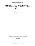
The following figure shows the relation between the files in an RTOS project and the development process.
2.2. Creating an RTOS Project
1.
First make sure you have an existing project. This is explained in the Getting Started manual of the
toolset. In this example we assume you have a project called myproject.
2.
From the File menu, select New » TASKING RTOS Configuration.
The New TASKING RTOS Configuration wizard appears.
3.
Select the Project folder for the RTOS configuration file: type the name of your project (myproject)
or click the Browse button to select a project.
7
Using the TASKING RTOS for TriCore
4.
In the File name field, enter a name for the RTOS configuration file, for example myproject.tskoil
and click Finish.
A new RTOS configuration file is added to the project with extension .tskoil, and it is opened
automatically in the TASKING RTOS Configurator.
Note that if you right-click on a project name and select New » TASKING RTOS Configuration the project
name and file name are already filled in.
2.3. Configuring the RTOS Objects and Attributes
When you have added a new RTOS configuration file, the TASKING RTOS Configurator initially looks
similar to this:
You use the TASKING RTOS Configurator to add and/or change RTOS objects and attributes. You can
add tasks, events, resources, alarms, interrupts, messages and counters.
As an example, make changes to this RTOS configuration as follows:
1.
From the RTOS menu, select New » TASK.
The New TASK Object dialog appears.
8
Getting Started
2.
In the Name field enter task0 and click OK.
TASK task0 is added to the configuration.
3.
Repeat steps 1 and 2 to add tasks task1 and task2.
4.
From the RTOS menu, select New » EVENT.
The New EVENT Object dialog appears.
5.
In the Name field enter E1 and click OK.
EVENT E1 is added to the configuration.
6.
Repeat steps 4 and 5 to add event E2.
7.
Click on the New_CPU value and change it to MyRTOS.
8.
Click on the New_OS value and change it to StdOS.
9.
Expand the OS object and change the ORTI attribute from FALSE to TRUE.
This will provide the debugger with as much RTOS debug information as possible via the ORIT
interface.
10. Click on the APPMODE1 value and change it to AP1.
11. Expand TASK task0 and change AUTOSTART to TRUE.
The APPMODE[0] attribute appears.
12.
Click in the Value field of APPMODE[0] and click on the Browse button
.
The Select APPMODE Objects dialog appears.
13. Select AP1 and click OK.
APPMODE[0] is changed into APPMODE[1] indicating it contains 1 APPMODE object.
14.
Click in the Value field of EVENT[0] and click on the Browse button
.
The Select EVENT Objects dialog appears.
15. Select E1 and E2 and click OK.
EVENT[0] is changed into EVENT[2] indicating it contains 2 EVENT objects.
16. Repeat steps 13 and 14 to add EVENT E1 to task1, and add EVENT E2 to task2
9
Using the TASKING RTOS for TriCore
The TASKING RTOS Configurator view now looks similar to this:
17. From the File menu, select Save (Ctrl+S) or click
.
The file will be saved and a question appears if you want to generate the RTOS code.
18. Click Yes to generate the RTOS code.
An rtos directory with the RTOS code is generated in your project directory.
2.4. Generate RTOS Code
Once you have changed the RTOS configuration file, you can generate the RTOS code. As seen in the
previous example, this can be done automatically each time you save the configuration. At any time you
can also click the Generate Code button (
10
).
Getting Started
2.5. TASKING RTOS Configurator Preferences
You can use the Preferences dialog in Eclipse to specify how the TASKING RTOS Configurator should
operate.
To set preferences
1.
From the Window menu, select Preferences.
The Preferences dialog appears.
2.
Select TASKING » TASKING RTOS Configurator.
The TASKING RTOS Configurator page appears.
3.
Set your preferences and click OK.
You can set the following preferences:
Generate code on save
By default the TASKING RTOS Configurator asks if you want to generate code when you save a document
(Prompt). You can choose to do this automatically (Always) or Never.
2.6. Edit the Application Files
Once the RTOS source code is in your project directory you can use it in your application files. In order
to get a working project, you must edit at least the main source file. It is not necessary to pay attention
to the exact contents of the file at this moment.
Edit the user source code
1.
As an example, type the following C source in the file myproject.c:
#include <rtos.h>
DeclareTask(task0);
DeclareTask(task1);
DeclareTask(task2);
DeclareEvent(E1);
DeclareEvent(E2);
DeclareAppMode(AP1);
int main(void)
{
StartOS(AP1);
return 0;
}
11
Using the TASKING RTOS for TriCore
TASK (task0)
{
EventMaskType event;
ActivateTask(task1);
while(1)
{
WaitEvent(E1 | E2);
GetEvent(task0, &event);
if (event & E1)
{
ActivateTask(task2);
}
else if (event & E2)
{
ActivateTask(task1);
}
ClearEvent(E1 | E2);
}
}
TASK (task1)
{
SetEvent(task0, E1);
TerminateTask();
}
TASK (task2)
{
SetEvent(task0, E2);
TerminateTask();
}
2.
From the File menu, select Save (Ctrl+S) or click
.
The file will be saved.
2.7. Set the Project Options
In order for your application to find the RTOS files, the rtos directory and the rtos/Configuration
directory must be in the list of include paths. When you generate the RTOS source code, these paths are
added to your project options automatically, if they were not present already. You can check the project
include paths as follows.
1.
From the Project menu, select Properties for
The Properties dialog appears.
2.
12
In the left pane, expand C/C++ Build and select Settings.
Getting Started
In the right pane the Settings appear.
3.
On the Tool Settings tab, expand C/C++ Compiler and select Include Paths.
4.
Make sure the following paths are present:
2.8. How to Build an RTOS Application
Once you have generated the RTOS code and created your application, you are ready to build the RTOS
application. This is the same as building any other C/C++ project.
• From the Project menu, select Build project (
).
2.9. How to Debug an RTOS Application
The debugger has special support for debugging real-time operating systems (RTOSs). This support is
implemented in an RTOS-specific shared library called a kernel support module (KSM) or RTOS-aware
debugging module (RADM). Specifically, the TASKING VX-toolset ships with a KSM (orti_radm.dll).
The TASKING OIl compiler creates an Run Time Interface (ORTI) file (oil.orti) in the
rtos/Configuration folder.
If you want as much RTOS debug information as possible via the ORTI interface, you must set the ORTI
attribute in the OS object of the RTOS configuration file to TRUE. In step 9 in Section 2.3, Configuring the
RTOS Objects and Attributes we already did this.
You need to specify the ORTI file on the Miscellaneous tab while configuring a customized debug
configuration:
1.
From the Debug menu, select Debug Configurations...
The Debug Configurations dialog appears.
2.
In the left pane, select the configuration you want to change, for example, TASKING C/C++ Debugger
» myproject.
3.
Open the Miscellaneous tab.
13
Using the TASKING RTOS for TriCore
4.
In the ORTI file field, specify the name of the ORTI file (oil.orti).
The KSM module field will automatically be filled with the file orti_radm.dll in the bin directory
of the toolset.
5.
Click Debug tot start the debugger.
To start kernel debugging you can use the ORTI menu entry in the Debug menu. Debug » ORTI » RTOS
allows inspection of all RTOS resources including system status, tasks, contexts, stacks and resources.
For example, to show the tasks:
• From the Debug menu, select ORTI » RTOS » Tasks.
The RTOS: Tasks view appears.
14
Chapter 3. RTOS Objects and Attributes
This chapter describes the available RTOS objects and attributes you can configure with the TASKING
RTOS Configurator.
3.1. What are the OIL System Objects?
Every version of OIL language defines syntactically and semantically a set of OIL system objects. These
objects are defined in the ISO standard. One of the system objects is CPU. This serves as a container
for all other objects. Objects are defined by their attributes.
3.1.1. Standard and Non-Standard Attributes
Every OIL system object has attributes that can hold values. According to the OIL standard, each object
has at least a minimum mandatory set of attributes, called the standard attributes. Besides the standard
attributes, an ISO 17356 implementation may define additional attributes (non-standard attributes) for
any OIL system object.
To configure a system for a specific ISO 17356 implementation you need to instantiate and/or define OIL
objects and assign values to their attributes.
An ISO 17356 implementation can limit the given set of values for object attributes.
Since the non-standard attributes are ISO 17356 implementation specific they are not portable. However,
there are two reasons to justify non-standard attributes:
• they can address platform specific features
• they can provide extra configuration possibilities for a certain target
3.1.2. Overview of System Objects and Attributes
The following table shows the list of system objects with their standard attributes as defined by OIL2.5
and the non-standard attributes for the TriCore. The non-standard attributes are marked italic.
Because the TASKING RTOS supports only internal communication, the subset of objects and standard
attributes differs from the OIL2.5 definition:
• MESSAGE object (TASKING RTOS differs)
• NETWORK MESSAGE object (not present in TASKING RTOS)
• COM object (TASKING RTOS differs)
• IPDU object (not present in TASKING RTOS)
In addition to the attributes listed in the table below, there are a number of non-standard attributes which
are not included in this table. These extra attributes all start with the keyword WITH_AUTO and take AUTO
15
Using the TASKING RTOS for TriCore
as their default value (you can search for them in the file rtos_impl.oil). This subset of attributes can
be considered as internals of the implementation and are not user configurable. Instead, their values are
calculated at generation time.
OIL system Description
object
CPU
The CPU on which the application runs under
the RTOS control. Container of all the other
objects.
OS
The OS that runs on the CPU. All system
objects are controlled by OS.
Standard attributes
Non-standard attributes
STATUS
STARTUPHOOK
ERRORHOOK
SHUTDOWNHOOK
PRETASKHOOK
POSTTASKHOOK
USEGETSERVICEID
USEPARAMETERACCESS
USERESSCHEDULER
LONGMSG
ORTI
RUNLEVELCHECK
SHUTDOWNRETURN
IDLEHOOK
IDLELOWPOWER
USERTOSIMER
APPMODE Defines different modes of operation for the Has no attributes
application.
TASK
The task handled by the OS.
PRIORITY
SCHEDULE
ACTIVATION
AUTOSTART
RESOURCE [ ]
EVENT [ ]
MESSAGE [ ]
STACKSIZE
ISR
Interrupt service routines supported by OS. CATEGORY
RESOURCE [ ]
MESSAGE [ ]
LEVEL
RESOURCE The resource that can be occupied by a task. RESOURCEPROPERTY
COUNTER The counter represents hardware/software
tick source for alarms.
MAXALLOWEDVALUE
TICKSPERBASE
MINCYCLE
EVENT
MASK
16
The event on which tasks may react.
RTOS Objects and Attributes
OIL system Description
object
Standard attributes
Non-standard attributes
ALARM
COUNTER
ACTION
AUTOSTART
The alarm is based on a counter and can
either activate a task or set an event or
activate an alarm-callback routine.
MESSAGE The message is defined in COM and defines MESSAGEPROPERTY
a mechanism for data exchange between
NOTIFICATION
different entities (tasks or ISRs)
COM
The communication subsystem. The COM
object has standard attributes to define
general properties for the interaction layer.
COMERRORHOOK
COMUSEGETSERVICEID
COMUSEPARAMETERACCESS
COMSTARTCOMEXTENSION
COMAPPMODE [ ]
COMSTATUS
3.1.3. Non-Standard Attributes for the TriCore
This section describes the non-standard attributes, which are specific for the TriCore.
Please refer to the ISO 17356 documentation for the semantics of all standard attributes.
OS object
Attribute
Description
IDLEHOOK
The IDLEHOOK attribute specifies the name of a user definable hook routine that
will be called from the idle task. The IDLESTACKSIZE sub-attribute specifies the
size of the stack used by the hook routine.
IDLELOWPOWER
When the IDLELOWPOWER is set, the idle task will enter low power mode by
executing the wait instruction. When both IDLEHOOK and IDLELOWPOWER
are set, the IDLEHOOK is executed first, before entering wait mode.
LONGMSG
The LONGMSG boolean attribute determines whether Category 2 ISRS are
suspended during the copy of messages from the RTOS buffers to the application
or vise versa. If set to TRUE, the RTOS expects long messages, so the interrupts
will not be suspended. This is at the cost of extra handling. The default value is
FALSE.
ORTI
With the ORTI attribute you can request the RTOS to provide the debugger with
as much RTOS debug information as possible via the ORTI interface. If you set
this attribute to TRUE, the run-time performance suffers from extra overhead that
should be avoided in final production. (If you set this attribute to FALSE, not all
debug information will be available to the debugger). The type of ORTI is
BOOLEAN. It has a default value of FALSE.
17
Using the TASKING RTOS for TriCore
Attribute
Description
SHUTDOWNRETURN When the SHUTDOWNRETURN attribute of the OS object is TRUE, after the
ShutdownOS() routine has finished it returns to main() just after the call to
StartOS(). If SHUTDOWNRETURN is FALSE, the function does not return.
The MULTISTART boolean sub-attribute specifies whether the system is allowed
to start the RTOS more than once (undergoing application resets via the usage
of ShutdownOS()). It has a default value of TRUE. See Section 4.5, Shut-down
Process in Chapter 4, Startup Process.
USERTOSTIMER
The USERTOSTIMER is a parametrized boolean attribute which determines
whether ALARM OIL objects based on the system counter have been configured
in the system. If set to TRUE, the RTOS provides the interrupt framework for the
timer unit and the application provides its initialization. In this case, you must set
the sub-attribute RTOSTIMERPRIO to the interrupt priority. This priority must be
in the range of ISR category 2. Priority 1 is the lowest priority. The type of
RTOSTIMERPRIO is UINT32. The default value is 1. You can choose any of the
timers T2, T3, T4, T5 or T6 for the RTOSTIMER. The default is T3. Set the
OSCLOCKHZ to the frequency of OS ticks in Hz. Set CPUCLOCKMHZ to the
processor clock frequency in MHz. The default value for USERTOSTIMER is
FALSE.
TASK object
Attribute
Description
STACKSIZE
The STACKSIZE attribute specifies the size of the stack area (in bytes) to allocate
for the task. Note that interrupts of category 1 may use this stack area. The type
of this attribute is UINT32. The default value is 250. See Section 5.7, The Stack
of a Task.
ISR object
Attribute
Description
LEVEL
The LEVEL attribute specifies the priority level of the interrupt. The type of this
attribute is UINT32. The default value is 1.
18
Chapter 4. Startup Process
This chapter explains what happens inside the system from application reset until the first application
task is scheduled and describes how you can interact with the startup process by adding certain Hook
Routines.
4.1. Introduction
This chapter details the various phases the system undergoes from CPU reset until the first application
task is scheduled. You can interact with this process via the Hook Routines and the Application Modes.
The startup process includes the following phases:
• System boot
• C entry point main()
• StartOS
• RTOS initialization phase: Hook Routines
After the startup process the first task is scheduled. When the startup has no tasks, the system idle task
is scheduled.
4.2. System Boot
When the processor first starts up, it always looks at the same place in the system ROM memory area
for the start of the system boot program. The boot code runs sequentially until it reaches the point where
it jumps to the label main. This code runs in the absence of the operating system.
In general, embedded systems differ so much from each other that the boot code tends to be almost
unique for each process. You can create the system boot in two ways:
• Reuse the standard startup code provided by the toolset and enhance it (if necessary) to suit the specific
needs of your hardware. The standard startup code merely contains what is necessary to get the system
running. It is easy configurable via Project Properties dialog.
• You may decide to create the system boot code if some board specific actions need to be taken at a
very early stage. Some of the most common actions are:
• Initialization of critical microprocessor registers (including standard pointers like the stack pointer).
• Initialization of specific peripheral registers for your unique hardware design.
• Initialization of all global variables.
• Distinguish the source of processor reset (hard or soft reset, power-on reset, watchdog, ...).
• Addition of some power-on tests.
19
Using the TASKING RTOS for TriCore
• Call the label main() to start the application.
4.3. The main() Module
At the moment of arriving in main() only minimal controller initialization has occurred. At this point the
application can run extra (application-specific) initialization routines before the RTOS starts. This code
cannot call RTOS system services.
The RTOS is started using the StartOs() routine:
void StartOS(AppModeType);
The AppModeType application mode parameter for the StartOs() routine is one of the APPMODE
application modes defined in the TASKING RTOS Configurator or OSDEFAULTAPPMODE, which is a define
supplied by the RTOS which maps to the first application mode.
4.3.1. What are Application Modes?
Application Modes allow you (as a matter of speaking) to have "multiple" applications in one single image.
Application Modes allow application images to structure the software running in the processor depending
on external conditions. These conditions must be tested by the application software upon system reset.
The difference in functionality between applications that start in different modes is determined by:
• Which tasks and which alarms automatically start after the RTOS initialization.
• Mode-specific code (the mode can be detected at run-time by using the system service
GetActiveApplicationMode).
You can set the AUTOSTART attribute to TRUE for a task in the TASKING RTOS Configurator, and then
add the application mode object. There is no limit on the number of Application Mode objects. See
Chapter 13, Implementation Parameters, for the maximum number of application modes in this
implementation.
4.4. RTOS Initialization
This section shows what happens inside the system from the moment that you call StartOS() until the
first application task is scheduled and explains how you can intervene in this process.
The RTOS performs the following actions during the initialization process:
1.
The RTOS initializes some internal data structures on the basis of what is stated in the RTOS
configuration file. In particular, it prepares autostarting tasks and alarms to start running.
2.
The RTOS hardware timer is initialized when the USERTOSTIMER attribute of the OS object is set
to TRUE.
The unit of time is the system tick (defined as the interval between two consecutive hardware clock
interrupts). The implementation parameter OSTICKDURATION defines the length (in nanoseconds)
of the system tick.
20
Startup Process
Not all applications need a system counter (only those with ALARM objects based on the system
counter). You determine this with the non-standard attribute USERTOSTIMER.
When you set USERTOSTIMER to TRUE, you need to set some extra attributes. For the TriCore
AURIX for example, you need to choose one of the GPT120 timers T2 .. T6 for RTOSTIMER. Set
RTOSTIMERPRIO to the interrupt priority. Set OSCLOCKHZ to the frequency of OS ticks in Hz and
set CPUCLOCKMHZ to the processor clock frequency in MHz.
3.
The RTOS calls the hook routine StartupHook() (provided that you have assigned the value TRUE
to the STARTUPHOOK attribute of the OS object in the RTOS configuration):
void StartupHook(void);
If the STARTUPHOOK attribute of the OS object is set but you do not define the
StartupHook() routine in your source, the linking phase fails because it encounters an
unresolved external.
During the lifetime of the StartupHook routine all the system interrupts are disabled and you have
only restricted access to system services. The only available services are
GetActiveApplicationMode() and ShutdownOS().
You should use this hook routine to add initialization code which strongly relies on the current selected
Application Mode.
void StartupHook(void)
{
AppModeType mode = GetActiveApplicationMode();
// .
// . code for StartupHook
// .
return;
}
4.
The RTOS enables all system interrupts.
5.
The RTOS executes the highest priority task ready to execute.
If you define the AUTOSTART attribute as FALSE for all TASK objects in the RTOS configuration,
the system enters directly into an RTOS-defined idle state. The system then waits for external
events or alarms based on the system counter.
4.5. Shut-down Process
The operating system can be shut-down by the ShutdownOS() routine:
void ShutdownOS(StatusType error);
21
Using the TASKING RTOS for TriCore
You can directly request the ShutdownOS() routine. In this case, you must define your own set of
shut-down reasons: error codes. The application can define its own error codes in the range 64 .. 255.
For example:
#define E_APP_ERROR1
#define E_APP_ERROR2
...
...
#define E_APP_ERROR192
64
65
255
(0-63 are reserved for the RTOS code)
As soon as your application encounters a fatal error, the ShutdownOS() routine must be called with an
appropriate error code. For example:
ShutdownOS(E_APP_ERROR1);
The ShutdownOS() routine can also be reached internally by the operating system in case the RTOS
encounters an internal fatal error.
See the file rtos.h in the rtos directory of your project for a list of system error codes. They start with
E_OS_ or E_OK if there are no errors.
When the SHUTDOWNRETURN attribute of the OS object is TRUE, after the ShutdownOS() routine
has finished it returns to main() just after the call to StartOS(). If SHUTDOWNRETURN is FALSE,
the function does not return.
SHUTDOWNRETURN has a sub-attribute MULTISTART. When MULTISTART is set to TRUE (the default)
you can restart the operating system by calling StartOS(). The global variables of the operating system
are then reset to their initial values. When MULTISTART is set to FALSE you cannot call StartOS()
again because the operating system variables have not been reset.
From the ShutdownOS() routine, the RTOS calls the hook routine ShutdownHook(), provided that you
have assigned the value TRUE to the SHUTDOWNHOOK attribute of the OS object in the RTOS
configuration.
void ShutdownHook(StatusType error);
If the SHUTDOWNHOOK attribute is set but you do not define the ShutdownHook() routine in
your source, the linking phase fails because it encounters an unresolved external.
During the lifetime of the ShutdownHook() routine all system interrupts are disabled and the only
available service is GetActiveApplicationMode().
You can define any system behavior in this routine, including not returning from the function at all. In any
case, you should always check for both application and RTOS error codes. Typical actions would be:
• If you run with a debugger, you can set a breakpoint in this routine to study the nature of the possible
shutdown reasons.
22
Startup Process
• In absence of a debugger, use a logging mechanism (be aware that ISR2 are disabled when this routine
is called).
• In case a fatal error is encountered, you should force the system to shut down (or hardware reset). All
RTOS errors are (by definition) fatal and you should decide whether any of your own application errors
should also be considered fatal (if any).
4.6. API Service Restrictions
System services are called from tasks, interrupt service routines, hook routines, and alarm callbacks.
Depending on the system service, there may be restrictions regarding the availability. See the following
table.
Service
Task
ISR
cat 1
ISR
cat 2
ActiveTask
✓
TerminateTask
✓
ChainTask
✓
Schedule
✓
GetTaskID
✓
GetTaskState
✓
DisableAllInterrupts
✓
✓
✓
EnableAllInterrupts
✓
✓
✓
SuspendAllInterrupts
✓
✓
ResumeAllInterrupts
✓
SuspendOSInterrupts
✓
ResumeOSInterrupts
✓
GetResource
✓
✓
ReleaseResource
✓
✓
SetEvent
✓
✓
ClearEvent
✓
GetEvent
✓
WaitEvent
✓
GetAlarmBase
Error Pre
hook task
hook
Post
task
hook
Startup Shut
hook
down
hook
alarm
callback
✓
✓
✓
✓
✓
✓
✓
✓
✓
✓
✓
✓
✓
✓
✓
✓
✓
✓
✓
✓
✓
✓
✓
✓
✓
✓
✓
✓
✓
✓
✓
✓
✓
GetAlarm
✓
✓
✓
✓
✓
SetRelAlarm
✓
✓
SetAbsAlarm
✓
✓
CancelAlarm
✓
✓
23
Using the TASKING RTOS for TriCore
Service
GetActiveApplicationMode
Task
ISR
cat 1
ISR
cat 2
Error Pre
hook task
hook
✓
✓
✓
✓
✓
✓
✓
Post
task
hook
✓
Startup Shut
hook
down
hook
✓
StartOS
ShutdownOS
24
✓
✓
alarm
callback
Chapter 5. Task Management
This chapter explains how the RTOS manages tasks (scheduling policies, tasks states, ..) and describes
how you can add TASK objects to the TASKING RTOS configuration.
5.1. What is a Task?
A task is a semi-independent program segment with a dedicated purpose. Most modern real-time
applications require multiple tasks. A task provides the framework for the execution of functions. The
RTOS provides concurrent and asynchronous execution of tasks. The scheduler organizes the sequence
of task execution including a mechanism which is active when no other system or application function is
active: the idle-mechanism.
A task has a static priority, is or is not preemptable, can or cannot enter the waiting state, is or is not the
only owner of a priority level, and so on.
5.2. Defining a Task in the C Source
To configure a task, you must declare a TASK object in the TASKING RTOS Configurator of the project.
An example is given in Section 2.3, Configuring the RTOS Objects and Attributes. See Section 3.1.2,
Overview of System Objects and Attributes for an overview of the possible attributes. See the ISO 17356
documentation for detailed information about all possible attributes of a task and how to use them.
With the macro TASK you can define a task in your application. Use the same name as the name of the
TASK object in the RTOS configuration as parameter to this macro.
A task must not return. Instead of a return statement, end the code of a task with the system service
TerminateTask() or ChainTask(). For example, to define the task TaskT:
TASK(TaskT)
{
.
. code for task 'TaskT'
.
TerminateTask();
}
If a task is needed as a parameter to a system service, for example ActivateTask(), you need to
declare the task first with DeclareTask().
DeclareTask(TaskT);
void fnc( void )
{
ActivateTask(TaskT);
}
25
Using the TASKING RTOS for TriCore
5.3. The States of a Task
A task goes through several different states during its lifetime. A processor can only execute one instruction
at a time. So, even when several tasks are competing for the processor at the same time, only one task
is actually running. The RTOS is responsible of saving and restoring the context of the tasks when they
undergo such state transitions.
A task can be in one of the following states:
Task state Description
running
The CPU is now assigned to the task and it is executing the task. Only one task can be in
this state at any point in time.
ready
All functional prerequisites for a transition into the running state exist, and the task only
waits for allocation of the processor. The scheduler decides which ready task is executed
next.
waiting
A task cannot continue execution because it has to wait for at least one event.
suspended In the suspended state the task is passive and can be activated.
5.4. The Priority of a Task
The scheduler decides on the basis of the task priority (precedence) which is the next of the ready tasks
to be transferred into the running state. The value 0 is defined as the lowest priority of a task and it is
reserved for the idle task.
To enhance efficiency, a dynamic priority management is not supported. Accordingly the priority of a task
is defined statically: you cannot change it during execution.
In special cases the operating system can treat tasks with a lower priority as tasks with a higher priority.
See Section 7.3, The Ceiling Priority Protocol, in Chapter 7, Resource Management.
An application can have more than one task with the same priority. The RTOS uses a first in, first out
(FIFO) queue for each priority level containing all the ready tasks within that priority. Some facts about
the ready-queues are listed below:
• Every ready-queue corresponds to a priority level.
• Tasks are queued, in activation order, in the ready-queue that corresponds to their static priority.
• All the tasks that are queued must be in the ready state.
• Since the waiting tasks are not in any ready queue, they do not block the start of subsequent tasks
with identical priority.
• The system priority corresponds to the highest priority among all of the non-empty ready-queues.
• The running task is the first task in the ready-queue with the system priority.
• A task being released from the waiting state is treated like the newest task at the end of the ready-queue
of its priority.
26
Task Management
• The following fundamental steps are necessary to determine the next task to be processed:
1. The scheduler searches for all tasks in the ready/running state.
2. From the set of tasks in the ready/running state, the scheduler determines the set of tasks with the
highest priority.
3. Within the set of tasks in the ready/running state and of highest priority, the scheduler finds the oldest
task.
5.4.1. Virtual versus Physical Priorities
We define virtual priority of a task as "the priority of a task as it is given in the RTOS configuration".
We define physical priority of a task as "the real run-time priority of the task".
Let us think of an application with three TASK objects defined such that:
TASK T1 { PRIORITY = 6; .. };
TASK T2 { PRIORITY = 4; .. };
TASK T3 { PRIORITY = 4; .. };
The "ready-to-run" array comprises all the ready queues of the system. In such a system there will be
two "ready-queues" in the "ready-to-run" array, one per priority level.
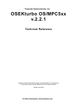
The following figure shows the "ready-to-run" array where T1 is running and tasks T2 and T3 are ready
(T2 being the oldest).
Figure 5.1. Virtual ready-to-run array
Now, what would, in terms of functionality, be the differences between this configuration and the next
systems?
System A
TASK T1 { PRIORITY = 3; .. };
TASK T2 { PRIORITY = 1; .. };
TASK T3 { PRIORITY = 1; .. };
27
Using the TASKING RTOS for TriCore
System B
TASK T1 { PRIORITY = 17;.. };
TASK T2 { PRIORITY = 9; .. };
TASK T3 { PRIORITY = 9; .. };
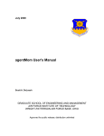
The equivalent "ready-to-run" arrays of such systems would then be:
Figure 5.2. Virtual ready-to-run array for System A
Figure 5.3. Virtual ready-to-run array for System B
There are no functional differences. As soon as T1 undergoes the wait or terminate transition, T2 is
scheduled. T2 can only be preempted by T1. T3 only runs after T2 undergoes a wait or terminate transition.
However, it is easy to infer from the diagrams that system A has the better run-time response of the
system. In system B, for instance, there are 15 "useless" priority levels defined in the system. Besides
these levels can never hold a ready task, the scheduler also wastes CPU cycles in checking them. And
RAM area has been allocated for them. In a hard real-time system, these unnecessary checks must be
avoided.
Since all this information can be interpreted beforehand by the RTOS code, all these configurations will
end up in the same physical "ready-to-run" array:
Figure 5.4. Virtual ready-to-run array for System A and System B
28
Task Management
Internally, the RTOS code deals always with "physical priorities". The maximum size of the "ready-to-run"
array determines the upper limit for the number of physical priorities.
5.4.2. Fast Scheduling
Every physical priority level holds a "ready-queue". You can define multiple tasks with the same priority.
However, if you define only one task per priority level, the scheduler becomes faster. In this situation the
RTOS software does not have to deal with "ready-queues" but merely with pointers to the task control
blocks.
Whenever possible, you should try to define only one TASK object with the same value for its PRIORITY
attribute. You will benefit not only from better run-time responses but also from smaller RAM and ROM
sizes.
5.5. Activating and Terminating a Task
Tasks must be properly activated and terminated. You can activate tasks directly from a task or interrupt
level. To activate a task, use the system service:
StatusType ActivateTask(TaskType task);
A task is activated by the RTOS code when:
• An alarm expires (with its attribute ACTION set to ACTIVATETASK).
• A message has been sent (with its attribute NOTIFICATION set to ACTIVATETASK).
• You configured a task to be activated during the RTOS startup. You must set the attribute AUTOSTART
to TRUE and indicate under which application mode(s) the task must autostart.
And the RTOS needs to be started in your C source:
DeclareAppMode(AppMode1);
int main(void)
{
StartOS(AppMode1);
return 0;
}
29
Using the TASKING RTOS for TriCore
After activation, the task is ready to execute from the first statement. The RTOS does not support C-like
parameter passing when starting a task. Those parameters should be passed by message communication
or by global variables. See Chapter 10, Communication.
A task can be activated once or multiple times. The maximum number of activations is defined in the
RTOS configuration with the attribute ACTIVATION of the TASK object.
If you try to activate a task which is in suspended mode, the RTOS will move the task into the ready state.
If you try to activate a task which is not in suspended mode (the task is ready, waiting or running - self
activation -), the RTOS will do the following, depending on the current number of activations:
• If the maximum number of activations, as specified by the ACTIVATION attribute, has not been reached
yet, the RTOS queues this activation request for further processing.
• If the maximum number of activations has been already reached, the system service returns E_OS_LIMIT
as error code.
Upon termination of a task, the RTOS checks for previous activation requests. If such a requests exist,
the RTOS will set the task to ready. Furthermore, if this task still has the highest priority of the system
(which is normally the case unless another task with higher priority has been activated or awaken from
an ISR2 or an alarm), the RTOS will immediately start this task again (with the initial context).
Example of activating a task
C source file:
TASK (Activate)
{
TerminateTask();
}
30
Task Management
TASK (Init)
{
int i;
StatusType ret;
/* 'Activate' task 5 times */
for (i = 0; i < 5; i++)
{
ret = ActivateTask(Activate);
if(ret != E_OK)
{
/* never here - always E_OK */
while(1);
}
}
/*
*
*
*
*/
for
{
try to activate five more times,
this will fail because maximum number of
activations is set to 5 in the RTOS Configuration
(i = 0; i < 5; i++)
ret = ActivateTask(Activate);
if (ret != E_OS_LIMIT)
{
/* never here - returns E_OS_LIMIT due to
* maximum number of activations reached
*/
while(1);
}
}
TerminateTask();
}
Terminating a task
You must explicitly terminate a task with one of the system services:
void TerminateTask(void);
or:
void ChainTask(TaskType);
If the return instruction is encountered at task level, the behavior is undefined.
31
Using the TASKING RTOS for TriCore
Situations like demonstrated in the example should be avoided:
TASK (TaskT)
{
unsigned char var = readPulse();
switch (var)
{
case READY:
sendSignal();
TerminateTask();
break;
case NONREADY:
TerminateTask();
break;
default:
break;
}
return;
}
Although apparently innocuous, the behavior of the whole system is completely undefined if var does
not equal to READY or NONREADY. In that case the switch reaches default where the function is not
properly terminated.
Be aware that calling TerminateTask from interrupts or from hook routines can bring the system to a
complete undefined state. You can call TerminateTask only from task level. See also
5.6. Scheduling a Task
A task can be scheduled with one of the following scheduling policies: full-preemptive and nonpreemptive
scheduling. You must assign a scheduling policy to every task in your RTOS configuration, setting the
attribute SCHEDULE of a TASK object to either FULL or NON.
5.6.1. Full-preemptive Tasks
Full-preemptive scheduling means that the running task can be rescheduled at any moment by the
occurrence of trigger conditions preset by the operating system. The running task enters the ready state,
as soon as a higher-priority task becomes ready.
The rescheduling points for full-preemptive scheduling are:
• Successful termination of a task.
32
Task Management
• Successful termination of a task with activation of a successor task (ChainTask).
• Activating a task at task level.
• Explicit wait call if a transition into the waiting state takes place.
• Setting an event to a waiting task at task level.
• Release of resource at task level.
• Return from interrupt level to task level.
If the tasks in the system are all full-preemptive, the scheduling policy of the system as whole is fully
preemptive. During interrupt service routines no rescheduling is performed.
5.6.2. Nonpreemptive Tasks
Nonpreemptive scheduling means that task switching is only performed via an explicitly defined system
services.
The explicit rescheduling points for nonpreemptive tasks are:
• Successful termination of a task.
• Successful termination of a task with explicit activation of a successor task.
• Explicit call of the scheduler.
• A transition into the waiting state.
If the tasks in the system are all nonpreemptive, the scheduling policy of the system as a whole is said
to be nonpreemptive.
Be aware of the special constraints that nonpreemptive scheduling imposes on possible timing requirements
while designing your TASK objects. A nonpreemptive task prevents all other tasks from CPU time so their
execution time should be extremely short.
5.6.3. Scheduling Policy
In the most general case, the system runs with the so-called mixed preemptive scheduling policy
(full-preemptive and nonpreemptive tasks are mixed). The current scheduling policy depends on the
preemption properties of the running task: nonpreemptive or full-preemptive. If the running task has its
SCHEDULE attribute set to FULL in the RTOS configuration, the scheduling policy is fully preemptive.
Otherwise the scheduling policy will be nonpreemptive.
Typically an application will operate in mixed preemptive mode where most of the tasks can be safely
preempted while the nonpreemptive tasks constitute only a small subset among all tasks.
The code below shows the behavior of the system with a mixed-preemptive policy.
33
Using the TASKING RTOS for TriCore
RTOS configuration:
C source file:
/* Like all other RTOS objects you need to declare
tasks before you can use them in your code */
DeclareTask(T1);
DeclareTask(T2);
DeclareTask(nP1);
34
Task Management
DeclareTask(nP2);
DeclareEvent(eT2_nP1);
TASK(T1)
{
TerminateTask();
}
TASK(T2)
{
/* To nP1 */
SetEvent(nP1,eT2_nP1)
TerminateTask();
}
TASK(nP1)
{
/* T1, T2, nP2 are activated but they cannot preempt the running task */
ActivateTask(T1);
ActivateTask(T2);
ActivateTask(nP2);
/* ... */
/* This call allows CPU scheduling to tasks with higher priority */
Schedule();
/* 1. T1 runs first and terminates */
/* 2. nP2 runs and terminates */
/* 3. nP1 resumes execution */
/* <--- An ISR activates T1 */
/* ... */
WaitEvent(eT2_nP1);
/* 1. T1 runs next and terminates */
/* 2. T2 runs. It sets 'eT2_nP1' to trigger again 'nP1' */
/* ... */
/* To T2 */
TerminateTask();
}
TASK(nP2)
{
TerminateTask();
}
35
Using the TASKING RTOS for TriCore
5.7. The Stack of a Task
Each task has its own data stack. All tasks en ISRs share from the processor context pool (CSA). The
size of the context pool is specified in the Special Areas tab of the Memory pane in the Properties dialog
of the project. The number of context blocks for core0 is 64 by default.
The stack size of a task is specified by the STACKSIZE attribute of a TASK object. You can change it in
the TASKING RTOS configurator. The default value is 250 bytes per task.
The user stack is used for cstart and the part of main() before StartOS() is called. RTOS objects
also use the user stack, for example ustack_tc0. Interrupts are on the interrupt stack, for example
36
Task Management
istack_tc0. Most system services run via a system call on the interrupt stack. The idle task runs on
its own stack.
5.8. C Interface for Tasks
You can use the following data types, constants and system services in your C sources to deal with task
related issues.
Element
C Interface
Data Types
TaskType
TaskRefType
TaskStateType
TaskStateRefType
Constants
RUNNING
WAITING
READY
SUSPENDED
INVALID_TASK
37
Using the TASKING RTOS for TriCore
Element
C Interface
System Services DeclareTask
ActivateTask
TerminateTask
ChainTask
Schedule
GetTaskID
GetTaskState
Please refer to the ISO 17356 documentation for a detailed description.
38
Chapter 6. Events
This chapter explains how the RTOS may synchronize tasks via events and describes how you can
declare EVENT objects in the RTOS Configurator in order to optimize your event configuration.
6.1. Introduction
Events are available as a synchronization method between tasks and between events and tasks. They
differentiate basic from extended tasks. Basically, every extended task has a private array of binary
semaphores. The array index corresponds with a bit position in an event mask. Thus, waiting on an event
mask implies a wait operation on multiple semaphores at a time.
You can:
• set an event from any task or from a Category 2 ISR (SetEvent)
• clear (or wait for) an event only from the running task (ClearEvent/WaitEvent)
• check which events have been set for a given task from any task, from a Category 2 ISR or from one
of the following hook routines: ErrorHook, PreTaskHook and PostTaskHook (GetEvent)
Since this implementation does not deal with external communication the scope of the events
limits to one application.
6.2. Adding Events
You can add or remove an EVENT in the RTOS Configurator.
1.
From the RTOS menu, select New » EVENT.
The New EVENT Object dialog appears.
2.
In the Name field enter the name of the event.
3.
Optionally enter a Description.
4.
Click OK.
The event is added to the configuration.
You cannot assign a mask value to an EVENT object. The RTOS Configurator always calculates this
value internally.
The maximum number of events supported by this implementation is 32. If you define more EVENT
objects in your RTOS configuration than the maximum number supported an error is issued.
39
Using the TASKING RTOS for TriCore
6.3. Using Events
WaitEvent
A task may enter the waiting state and allow other tasks the CPU time until a certain event occurs. Thus
events form the criteria for the transition of tasks from the running state into the waiting state. The transition
is performed with the system service:
StatusType WaitEvent(EventMaskType);
You can call WaitEvent (and ClearEvent) only from tasks for events that are listed in the attribute
EVENT of the task.
The following RTOS configuration specifies that task Task1 can only wait for Event1 and Event2:
If task Task1 attempts to wait for another event than Event1 or Event2, the system service WaitEvent
fails:
C source file:
TASK(Task1)
{
StatusType ret;
/* TASK waits for allowed event */
ret = WaitEvent(Event1);
if (ret != E_OK)
{
LogError(OSServiceID_WaitEvent, ret);
TerminateTask();
}
/* CPU has been given to other task(s)
/* From another TASK/ISR/ALARM the event
* 'E1' has been set for this task.
*/
40
Events
* Now 'T1' can resume execution
*/
/* TASK attempts to wait on an event that is not
* in the EVENTs list attribute of the TASK
*/
ret = WaitEvent(Event3);
if (ret != E_OK)
{
/* 'E3' is not owned by 'T1' */
LogError(OSServiceID_WaitEvent, ret);
TerminateTask();
}
/* ... */
TerminateTask();}
When the scheduler moves the task from the ready to the running state, the task resumes execution at
the following immediate instruction.
A task can wait for several events at a time:
WaitEvent(Event1 | Event2 | ...);
The task does not undergo the transition if just one of the events has occurred. In this case the service
immediately returns and the task remains in the running state. Only when all the events are cleared for
the calling task, the invoking task is put into the waiting state.
WaitEvent() can only be invoked from the task level of an extended task, never from interrupt level or
a hook routine.
SetEvent
You can set an event (equivalent to "an event occurs") to a specific task directly with the system service:
StatusType SetEvent(TaskType,EventMaskType);
If you need to trigger an event for more than one task you need to call SetEvent() for each combination
of task and event. You can set multiple events for a task at the same time.
An event can be set indirectly by the RTOS code upon expiration of an alarm (the ACTION attribute of
the alarm must be set to SETEVENT and the event must be added to the TASK object) or when a message
is transmitted (the NOTIFICATION attribute of the message must be set to SETEVENT).
Events can be set from interrupt level.
You cannot set events to suspended tasks.
41
Using the TASKING RTOS for TriCore
You can set several events at a time for a waiting task or ready task:
SetEvent( Task1, Event1 | Event2 | ...)
If Task1 is waiting for any of the triggered events it will enter the ready state. If the task is ready, the
events remain set. You can clear the events with ClearEvent().
GetEvent
You can check which events have been set for a given task with the system service:
StatusType GetEvent(TaskType,EventMaskRefType);
You can call this service to distinguish which event triggered the task and then take the corresponding
action. This service can be called from a hook routine or from interrupt level.
TASK(Task2)
{
StatusType
EventMaskType
TaskType
ret;
events;
id;
/* Wait for any of the three events */
ret = WaitEvent(Event1 | Event2 | Event3);
if (ret != E_OK)
{
LogError(OSServiceID_WaitEvent, ret);
TerminateTask();
}
/* Which events are pending */
ret = GetTaskID(&id);
if (ret != E_OK)
{
LogError(OSServiceID_GetTaskID, ret);
TerminateTask();
}
ret = GetEvent(id, &events);
if (ret != E_OK)
{
LogError(OSServiceID_GetEvent, ret);
TerminateTask();
}
/* handle events */
if (events & Event1)
{
Action1();
}
if (events & Event2)
42
Events
{
Action2();
}
if (events & Event3)
{
Action3();
}
TerminateTask();
}
Every time Task2 gets activated (events are all cleared) it waits for one of the three events. When running
again, it uses GetEvent() to find out which events have triggered the task.
ClearEvent
You can clear events yourself with the system service:
StatusType ClearEvent(EventMaskType);
You can call ClearEvent (and WaitEvent) only from tasks for events that are listed in the attribute
EVENT of the task. Never from a hook routine or an interrupt.
Adding this service to the previous example you can build a simplified version of an event handler task:
TASK(eventHandler)
{
StatusType
ret;
EventMaskType events;
TaskType
id;
while(1)
{
/* Wait for any of the three events */
ret = WaitEvent(Event1 | Event2 | Event3);
if (ret != E_OK)
{
LogError(OSServiceID_WaitEvent, ret);
TerminateTask();
}
/* Which events are pending */
ret = GetTaskID(&id);
if (ret != E_OK)
{
LogError(OSServiceID_GetTaskID, ret);
TerminateTask();
}
ret = GetEvent(id, &events);
if (ret != E_OK)
43
Using the TASKING RTOS for TriCore
{
LogError(OSServiceID_GetEvent, ret);
TerminateTask();
}
/* Clear events */
ClearEvent(events);
/* handle events */
if (events & Event1)
{
Action1();
}
if (events & Event2)
{
Action2();
}
if (events & Event3)
{
Action3();
}
}
TerminateTask();
}
DeclareEvent
Like all other RTOS objects you need to declare the event before using it in your source:
DeclareEvent(Event1);
TASK (TaskT)
{
...
WaitEvent(Event1);
}
6.4. The C Interface for Events
You can use the following data types and system services in your C sources to deal with event related
issues.
Element
C Interface
Data Types
EventMaskType
EventMaskRefType
Constants
-
44
Events
Element
C Interface
System Services DeclareEvent
SetEvent
ClearEvent
GetEvent
WaitEvent
Please refer to the ISO 17356 documentation for a detailed description.
45
Using the TASKING RTOS for TriCore
46
Chapter 7. Resource Management
This chapter explains how the RTOS may synchronize tasks via resources and describes how you can
declare RESOURCE objects in the RTOS Configurator.
7.1. Key Concepts
Critical code
A critical code section is a piece of software that must be executed atomically to preserve data integrity
and hardware integrity. Critical code sections handle for example:
• access to shared variables.
• most manipulations of linked lists.
• code that increment counters
An example of critical code is:
g = g + 1;
If global variable g is initially set to zero and two processes both execute this code, as a result the value
of g should be incremented to 2. If Process A executes the code and then Process B does, the result will
be correct. However, if A executes and, during the increment instruction, process B also executes the
same code, g may only be incremented to 1.
Mutex
A software entity that prevents multiple tasks from entering the critical section. Acquiring mutexes
guarantees serialized access to critical regions of code and protects the calling task from being preempted
in favor of another task (which also attempts to access the same critical section), until the mutex is dropped.
Priority inversion
A lower priority task preempts a higher priority task while it has acquired a lock. (See also Section 7.3.1,
Priority Inversion.)
Deadlock
The impossibility of task execution due to infinite waiting for mutually locked resources. (See also
Section 7.3.2, Deadlocks.)
Since OS is meant to operate in a critical environment (like the automobile industry) both priority inversion
and deadlocks are unacceptable.
47
Using the TASKING RTOS for TriCore
7.2. What is a Resource?
Resources are used to coordinate concurrent access of several tasks with different priorities to shared
resources. During these processes, the RTOS guarantees that two tasks or interrupt routines do not
occupy the same resource at the same time.
A resource is equivalent to what the literature commonly refers to as semaphores or mutexes.
Resources are an abstract mechanism for protecting data accesses by multiple tasks or ISRs. A resource
request effectively locks the corresponding data against concurrent access by another task. This is usually
called a mutex lock. It is implemented by temporarily raising the priority of the calling task so that possible
other contending lock requests cannot actually happen during the duration of the lock. This mechanism
is also known as the Priority Ceiling Protocol (see Section 7.3, The Ceiling Priority Protocol). The important
aspect of this particular mutex implementation is that the resource request never waits. This makes it
specially suitable for ISRs. In this regard, the priority levels are internally expanded to include all maskable
interrupt levels on top of the highest real priority level.
Some general ideas are listed below:
1. You must define resources for critical sections that you encounter in the system which are liable to
concurrency problems.
2. You configure resources in your RTOS configuration:
1.
From the RTOS menu, select New » RESOURCE.
The New RESOURCE Object dialog appears.
2.
In the Name field enter the name of the resource.
3.
Optionally enter a Description.
4.
Click OK.
The resource is added to the configuration.
3. In the RTOS Configurator you can configure a task or an interrupt service routine to own a resource
(a task or an interrupt service routine owning a resource means that they can occupy and release the
resource).
Example
Let us assume that Task1, Task2 and an asynchronous interrupt service routine named IsrA, need
to update the same global counter acounter. You must configure a new RESOURCE object and
define Task1, Task2 and IsrA as owners of the resource.
48
Resource Management
RTOS configuration:
The following source code makes sure that the counter update does not suffer from concurrency
problems.
C source file:
volatile int acounter;
TASK(Task1)
{
GetResource(Resource1);
acounter--;
ReleaseResource(Resource1);
TerminateTask();
}
TASK(Task2)
{
GetResource(Resource1);
acounter--;
ReleaseResource(Resource1);
49
Using the TASKING RTOS for TriCore
TerminateTask();
}
ISR(IsrA)
{
GetResource(Resource1);
acounter++;
ReleaseResource(Resource1);
}
4. Try to avoid superfluous resource definitions. A resource that is owned by only one task is useless. It
decreases the performance of the system because:
• Memory is allocated with the configuration data for a useless resource.
• Execution speed decreases because of useless system services around not even real critical code.
• Longer internal searches of the RTOS.
So, a resource should be owned by at least two tasks, by a task and an interrupt service routine or by
two interrupt service routines.
5. You should define only one RESOURCE object for all the critical sections accessed by the same
occupiers.
Let us assume that a second counter scounter needs to be updated globally by these three actors.
There is no need yet to change the RTOS configuration.
TASK (Task1)
{
GetResource(Resource1);
scounter--;
ReleaseResource(Resource1);
...
GetResource(Resource1);
acounter--;
ReleaseResource(Resource1);
...
}
TASK (Task2)
{
GetResource(Resource1);
acounter--;
scounter--;
ReleaseResource(Resource1);
}
ISR (IsrA)
{
GetResource(Resource1);
50
Resource Management
acounter++;
scounter++;
ReleaseResource(Resource1);
}
But in case this second global counter needs to be updated by a third task Task3 and a second ISR
IsrB then change the RTOS configuration:
51
Using the TASKING RTOS for TriCore
C source file:
TASK (Task1)
{
...
GetResource(Resource1);
scounter--;
ReleaseResource(Resource1);
...
GetResource(Resource2);
acounter--;
ReleaseResource(Resource2);
...
}
TASK (Task2)
{
...
GetResource(Resource2);
acounter--;
ReleaseResource(Resource2);
GetResource(Resource1);
scounter--;
ReleaseResource(Resource1);
...
}
TASK (Task3)
{
...
GetResource(Resource2);
scounter--;
ReleaseResource(Resource2);
...
}
ISR (IsrA)
{
...
GetResource(Resource2);
acounter--;
ReleaseResource(Resource2);
GetResource(Resource1);
scounter--;
ReleaseResource(Resource1);
...
}
ISR (IsrB)
{
...
GetResource(Resource2);
scounter--;
ReleaseResource(Resource2);
52
Resource Management
...
}
6. You cannot use the system services TerminateTask, ChainTask, Schedule, and/or WaitEvent
while a resource is being occupied.
ISR (Task1)
{
...
GetResource(Resource1);
acounter--;
/* This is forbidden - even if Event1 is
owned by Task1 */
WaitEvent(Event1);
ReleaseResource(Resource1);
...
}
7. The RTOS assures you that an interrupt service routine is only processed under the condition that all
resources that might be needed by that interrupt service routine are released.
TASK (Task2)
{
...
GetResource(Resource2);
/* IsrA and IsrB disabled */
acounter++;
ReleaseResource(Resource2);
GetResource(Resource1);
/* IsrA disabled */
scounter--;
ReleaseResource(Resource1);
...
}
8. Make sure that resources are not still occupied at task termination or interrupt completion since this
scenario can lead the system to undefined behavior. You should always encapsulate the access of a
resource by the calls GetResource and ReleaseResource. Avoid code like:
GetResource(Resource1);
...
switch ( condition )
{
case CASE_1 :
do_something1();
ReleaseResource(Resource1);
break;
case CASE_2 : /* WRONG: no release here! */
do_something2();
break;
default:
53
Using the TASKING RTOS for TriCore
do_something3();
ReleaseResource(Resource1);
}
9. You should use the system services GetResource and ReleaseResource from the same functional
call level. Even when the function foo is corrected concerning the LIFO order of resource occupation
like:
void foo( void )
{
ReleaseResource( Resource1 );
GetResource( Resource2 );
/* some code accessing resource Resource2 */
...
ReleaseResource( Resource2 );
}
there still can be a problem because ReleaseResource(Resource1) is called from another level
than GetResource(Resource1). Calling the system services from different call levels can cause
problems.
10. There is no need to define RESOURCE objects to protect critical code which can only be accessed
by tasks with the same priority. The reason is simple: the RTOS does not have round-robbin scheduling
of tasks at the same priority level, we can conclude that two (or more) tasks, with same priority, accessing
critical code will not suffer concurrency problems.
This is the basic idea behind the concept of the ceiling priority protocol.
11. Be careful using nested resources since the occupation must be performed in strict last-in-first-out
(LIFO) order (the resources have to be released in the reversed order of their occupation order).
TASK(Task1)
{
GetResource(Resource1);
...
GetResource(Resource2);
...
ReleaseResource(Resource2);
ReleaseResource(Resource1);
}
The following code sequence is incorrect because function foo is not allowed to release resource
Resource1:
TASK(incorrect)
{
GetResource( Resource1 );
/* some code accessing resource Resource1 */
...
foo();
...
54
Resource Management
ReleaseResource( Resource2 );
}
void foo()
{
GetResource( Resource2 );
/* code accessing resource Resource2 */
...
ReleaseResource( Resource1 );
}
12. The RTOS does not allow nested access to the same resource. In the rare cases where you need
nested access to the very same resource, it is recommended to use a second resource with the same
behavior (so-called linked resources).
You can configure linked resources in your RTOS configuration like:
13. Like all other RTOS objects you need to declare a resource before using it in your C source:
DeclareResource(Resource1);
TASK (Task1)
{
GetResource(Resource1)
...
}
7.3. The Ceiling Priority Protocol
The ceiling priority protocol is used in order to eliminate priority inversion and deadlocks.
7.3.1. Priority Inversion
A typical problem of common synchronization mechanisms is priority inversion. This means that a
lower-priority task delays the execution of higher-priority task.
Let us assume three tasks T1, T2 and T3 with increasing priorities (T1 has the lowest priority and T3 the
highest). T1 is running and the others are suspended. All tasks are fully preemptable.
Let us assume that T1 and T3 share resource R. Theoretically, the longest time that T3 can be delayed
should be the maximum time that T1 locks the resource R.
55
Using the TASKING RTOS for TriCore
However let us see what happens in the following time sequence:
1. T1 occupies the resource R.
2. T2 and T3 are activated.
3. T3 preempts T1 and immediately requests R.
4. As R is occupied T3 enters the waiting state.
5. The scheduler selects T2 as the running task.
6. T1 waits till T2 terminates or enters the waiting state.
7. T1 runs again and releases R.
8. T3 immediately preempts T1 and runs again.
Although T2 does not use resource R, it is in fact delaying T3 during its lifetime. So a task with high priority
sharing a resource with a task with low priority can be delayed by tasks with intermediate priorities. That
should not happen.
7.3.2. Deadlocks
Deadlocks are even more serious when locking resources causes a conflict between two tasks. Each
task can lock a resource that the other task needs and neither of the two is allowed to complete.
Imagine what would happen in the following scenario:
1. Task T1 occupies the resource R1.
2. Task T2 preempts T1.
3. Task T2 occupies resource R2.
4. Task T2 attempts to occupy resource R1 and enters the waiting state.
5. Task T1 resumes, attempts to occupy resource R2 and enters the waiting state.
6. This results in a deadlock. T1 and T2 wait forever.
With a properly designed application you can avoid deadlocks but this requires strict programming
techniques. The only real safe method of eliminating deadlocks is inherent to the RTOS itself. This RTOS
offers the priority ceiling protocol to avoid priority inversion and deadlocks.
7.3.3. Description of The Priority Ceiling Protocol
The principles of the ceiling priority protocol can be summarized as follows:
• At system generation, the RTOS assigns to each resource a ceiling priority. The ceiling priority is set
at least to the highest priority of all tasks that access a resource or any of the resources linked to this
resource. The ceiling priority must be lower than the lowest priority of all tasks that do not access the
resource, and which have priorities higher than the highest priority of all tasks that access the resource.
56
Resource Management
• If a task requires a resource, and its current priority is lower than the ceiling priority of the resource,
the priority of the task will be raised to the ceiling priority of the resource.
• If the task releases the resource, the priority of this task will be reset to its original (rescheduling point).
The problem of priority inversion is eliminated since only one task is actually capable of locking a resource.
Referring to the example in Section 7.3.1, Priority Inversion:
1. T1 gets the resource and the RTOS raises its priority to the ceiling priority of the resource R.
2. T3 is activated and remains in the ready state (at least while T1 locks resource R) since its priority is
never higher than the current priority of the system. Remember that T1 can neither terminate nor wait
for an event at this phase.
3. T2 is also activated and remains in the ready state.
4. T1 finally releases the resource. The RTOS revers its priority to its normal static level. This is a point
of rescheduling: T3 starts running.
5. T3 terminates and T2 starts running.
6. T2 terminates and T1 resumes running.
The only drawback is that T2 is inhibited by a lower priority task, T1. But this occurs only during the locking
time which can be calculated and/or minimized. The latency time in this scenario for T2 is far less than
for T3 in the previous case.
Deadlock is also easily eliminated because T2 cannot preempt T1. T1 must occupy and release (LIFO)
R1 and R2 before T2 attempts to take R2.
Ceiling Priority Protocol at Interrupt levels
The extension of the ceiling priority protocol to interrupt levels is also simple in this implementation:
Suppose that a resource R is owned by the interrupt service routines ISR1...ISRn and tasks T1 .. Tn. Let
P be the maximum interrupt priority level of these ISRs.
When task Tj occupies R, Tj behaves as a nonpreemptive task and all the ISR interrupts with priority P
(and lower) are temporarily disabled (all R owners included). Thus, while Tj owns the resource, it can
only be preempted by interrupts with a priority higher than P. Since Tj runs as nonpreemptable, even if
high priority tasks are activated from an ISR2 interrupt with higher priority than P, they will not be scheduled
until Tj releases resource R.
When the task Tj releases R, the priority of this task is reset to its original (rescheduling point). Possible
pending interrupts (with priority P or lower) and/or higher priority ready tasks (activated by interrupts with
priority higher than P) are now allowed to execute.
When the interrupt service routine ISRj gets resource R, all other ISR interrupts with priority P (and lower)
are temporarily disabled (this includes all other R owners) until R is released. The RTOS must handle
possible nested accesses to resources at different priority levels.
57
Using the TASKING RTOS for TriCore
7.4. Grouping Tasks
What is a group of Tasks?
The RTOS allows tasks to combine aspects of preemptive and nonpreemptive scheduling by defining
groups of tasks.
For tasks which have the same or lower priority as the highest priority within a group, the tasks within the
group behave like nonpreemptive tasks. For tasks with a higher priority than the highest priority within
the group, tasks within the group behave like preemptive tasks.
How to group Tasks
You can use an internal resource to define explicitly a group of tasks (or equivalently: a group of tasks is
defined as the set of tasks which own the same internal resource).
The RTOS automatically takes the internal resource when an owner task enters the running state (not
when the task is activated). As a result, the priority of the task is automatically changed to the ceiling
priority of the resource. At the points of rescheduling the internal resource is automatically released (the
priority of the task is set back to the original).
In the following configuration all the tasks are initially suspended. An event triggers the task in_1 to
activate. The idle task is preempted and the task in_1 will start execution. Because it owns the internal
resource in_resource, the task starts running with the ceiling priority of in_resource (3) instead of
with its static priority (1). This is the starting point in next example.
58
Resource Management
Example
RTOS configuration:
59
Using the TASKING RTOS for TriCore
C source file:
DeclareTask(in_1);
DeclareTask(in_2);
DeclareTask(in_3);
DeclareTask(out_1);
DeclareTask(out_2);
int
int
int
int
int
out_1_cnt;
out_2_cnt;
in_1_cnt;
in_2_cnt;
in_3_cnt;
TASK (out_1)
{
out_1_cnt++;
TerminateTask();
}
TASK (out_2)
{
out_2_cnt++;
TerminateTask();
}
TASK (in_1)
{
in_1_cnt++;
ActivateTask(out_1);
/* in_1 runs; out_1 is ready */
ActivateTask(in_3);
/* in_1 runs: in_3 is ready */
ActivateTask(out_2);
/* out_2 has run */
/* in_1 resumes execution */
Schedule();
/* in_3 and out_1 have run */
TerminateTask();
}
TASK (in_2)
{
in_2_cnt++;
TerminateTask();
}
TASK (in_3)
{
in_3_cnt++;
60
Resource Management
TerminateTask();
}
Features of internal resources are:
• A task can belong exclusively to a one group of tasks therefore owning a maximum of one internal
resource.
• Internal resources cannot be occupied and/or released in the standard way by the software application
but they are managed strictly internally within a clearly defined set of system functions.
Determining the most appropriate range for the priorities of tasks owning an internal resource, becomes
a key factor in the design. In most cases, this range of priorities should be reserved exclusively for the
members of the group. Otherwise, low priority tasks in the group could delay tasks outside the group with
higher priority. This is exactly what has happened in the previous example: out_1 was delayed by in_1.
7.5. The Scheduler as a Special Resource
The scheduler can be considered as a special resource that can be locked by the running task. As a
result, while the running task has locked the scheduler, it behaves like a nonpreemptive task (with the
same rescheduling points).
If you plan to use the scheduler as a resource, you must first set the attribute USERESSCHEDULER to
TRUE in the OS object of your RTOS configuration. C source code then can look as follows:
TASK(Task1)
{
...
/* preemptable */
GetResource(RES_SCHEDULER);
/* I am non-preemptable */
ReleaseResource(RES_SCHEDULER);
/* preemptable */
...
}
• You can neither define nor configure this resource. It is a system resource that is added by the RTOS
Configurator automatically.
• You do not need to add it to the resource list of any task.
• Interrupts are received and processed irrespective of the state of the resource.
61
Using the TASKING RTOS for TriCore
7.6. The C Interface for Resources
You can use the following data types, constants and system services in your C sources to deal with
resource related issues.
Element
C Interface
Data Types
ResourceType
Constants
RES_SCHEDULER
System Services DeclareResource
GetResource
ReleaseResource
Please refer to the ISO 17356 documentation for a detailed description.
62
Chapter 8. Alarms
This chapter describes how the RTOS offers alarm mechanisms based on counting specific recurring
events and describes how you can add these objects in the RTOS Configurator in order to specify your
alarm configuration.
8.1. Introduction
The RTOS provides services for processing recurring events. A recurring event is an abstract entity which
has been defined in the scope of a particular application. Each application monitors its events, therefore,
differently. A "wheel has rotated five more degrees" or "routine f has been called" could be examples of
recurring events.
Each of these recurring events can be registered in a dedicated counter (a COUNTER object). You must
increment this counter each time the associated event occurs. In the 'wheel' example, you probably
increment the counter in an interrupt service routine. In the 'routine' example, you increment the counter
in the body of f.
Based on these counters, you can install alarms. "Activation of a specific task every time the wheel rotates
180 degrees" or "setting an event when routine f has been called ten times" are examples of such alarms.
We say that an alarm expires when the counter reaches a preset value. You can bind specific actions to
alarms and the RTOS will execute these actions upon expiration of the alarms.
8.2. Counters
8.2.1. What is a Counter?
A counter is an abstract entity directly associated with a recurring event. The counter registers happenings
of its event (ticks) in a counter value (which must be incremented every time the event takes place).
The only way to interact with a counter is via IncrementCounter().
Assume that your application needs to monitor the rotation of a wheel. Your application software, project
agreement, works with one degree as the atomic unit in the system. You can define a COUNTER object
in the RTOS configuration to represent the rotated angle:
MAXALLOWEDVALUE is set to 359 since this corresponds to one complete full turn (360 degrees is
equivalent to 0 degrees).
MINCYCLE depends on the application sensibility and/or the hardware itself. In this example, your
application cannot log any action that happens before the wheel has rotated five degrees.
63
Using the TASKING RTOS for TriCore
You build the application regardless of the hardware interface that shall, eventually, monitor the wheel
rotation. Ideally the dependency on such a device should be minimized.
Suppose three different sensors S1, S2, S3 are candidates for the hardware interface. They all interface
equally with your chip (the pulse is converted into an external I/O hardware interrupt). But they send the
pulses at different rates, S1 every quarter of a degree, S2 every half a degree and S3 every degree.
The impact of this on your application is minimal. You only need to modify the TICKSPERBASE attribute
of your RTOS configuration. This attribute defines how many ticks are requested to increase the counter
unit by one. Hence, the value for the attribute must be 4 (if S1), 2 (if S2) and 1 (if S3).
If we select S2, the RTOS configuration for COUNTER would look as follows:
After RTOS code generation, the attribute values of counter sensorC are available to your application
as constants:
OSMAXALLOWEDVALUE_sensorC : 359
OSTICKSPERBASE_sensorC
: 2
OSMINCYCLE_sensorC
: 5
If the counter demands hardware or software initialization, you can use the StartUpHook() routine to
place the initialization code.
You are responsible for detecting the recurring events of your own counters and, as a follow-up, notifying
the RTOS. You must inform the RTOS about the arrival of a new sensor tick with the system service:
DeclareCounter(sensorC);
ISR (sensorHandler)
{
IncrementCounter(sensorC);
...
}
sensorHandler must be ISR Category 2.
See Section 9.3, Defining an Interrupt in the C Source.
8.2.2. The RTOS System Counter
The RTOS always offers a counter that is derived from a hardware timer. This counter is known as the
system counter.You can neither define nor configure this counter in the RTOS configuration. It is a counter
that is always present in the RTOS configuration and is called SYSTEM_COUNTER.
The unit of time is the system tick (as the interval between two consecutive hardware clock interrupts).
64
Alarms
The RTOS parameter OSTICKDURATION defines the length (in nanoseconds) of the system tick. If you
want to time certain actions in your application, you must declare an alarm with the system counter as a
counter:
If you plan to use the system counter, i.e. if you define ALARM objects that are based on the
SYSTEM_COUNTER, you first need to set the non-standard attribute of the OS object USERTOSTIMER
to TRUE.
The RTOSTIMERPRIO sub-attribute specifies the interrupt priority. The RTOS needs this information to
build the interrupt framework. The timer interrupt behaves as a Category 2 ISR (See Section 9.4, The
Category of an ISR Object to learn what Category 1 and Category 2 interrupts are).
For TriCore GPT120 you can set RTOSTIMER to one of the timers T2, T3, T4, T5 or T6. T6 has an auto
reload capability. The other timers are reloaded in the interrupt handlers. T6 is the most accurate timer.
You are not allowed to call the IncrementCounter() system service to increase the system counter.
You can use the following system constants related to the system counter in your application:
• OSMAXALLOWEDVALUE
This value determines the upper limit for the timer value unit.
65
Using the TASKING RTOS for TriCore
• OSTICKSPERBASE
This value determines how many clock ticks constitute a timer unit.
• OSMINCYCLE
This value represents an absolute minimum for the possible expiring times of system alarms. You can
set alarms which actions are meant to happen after OSMINCYCLE time units.
• OSTICKDURATION
The timer duration in nanoseconds.
8.3. What is an Alarm?
An alarm is a counter based mechanism to provide services to activate tasks, set events or call specific
routines when the alarm expires. When you set an alarm, you basically state two things: (1) a preset value
for the counter and (2) the action to be triggered when the counter reaches that value.
1. Alarm have an associated counter. Multiple alarms can be associated to the same counter.
2. In the RTOS configuration you must configure the action to be performed when the alarm expires. This
information is permanent: it is not possible to change the associated action to an alarm at run-time.
3. You can configure an alarm to set a specific event when the alarm expires. In that case, you must
specify which event is set and to which task.
When the alarm reaches the preset value, the RTOS code sets event sensorE to task sensorT. If
task sensorT waits for such an event (normal case) this becomes a point of rescheduling.
66
Alarms
4. You can configure an alarm to activate a certain task when it expires:
When the alarm reaches the preset value, the RTOS code will try to activate task sensorT. If task
sensorT is in the suspended state, this becomes a point of rescheduling.
5. You can configure an alarm to run a callback routine when it expires.
A callback must be defined in the application source like:
ALARMCALLBACK(sensorCB)
{
/* application processing */
}
The processing level of a callback is an Interrupt Service Routine level and runs with Category 2
interrupts disabled. Therefore the RTOS expects very short code for the callback routines.
6. You can use the system service SetRelAlarm() to predefine a counter value for an alarm to expire
relative to the actual counter value:
StatusType SetRelAlarm(AlarmType alarm,
TickType increment, TickType cycle);
When this system service is invoked, the alarm is set to expire at the current value of the counter plus
an increment (if the alarm is not in use, obviously). The increment value must be at least equal to the
MINCYCLE attribute of the associated counter.
The cycle parameter determines whether the alarm is periodic or not. If not zero, the alarm is restarted
upon expiration with cycle as a new time-out interval (at least equal to the MINCYCLE attribute of
the associated counter). If cycle equals to zero, the alarm will not be restarted.
This service can be called at task or interrupt level but not from hook routine level. Below you will find
an example of how to install an alarm that will activate task sensorT every 90 degrees:
SetRelAlarm(sensorAA,90,90);
67
Using the TASKING RTOS for TriCore
7. You can use the system service SetAbsAlarm() to predefine a counter value for an alarm to expire
in absolute terms:
Type SetAbsAlarm(AlarmType alarm,TickType increment, TickType cycle);
When this system service is invoked the alarm is set to expire at an specific absolute value of the
counter (if the alarm is not in use, obviously). The cycle determines whether the alarm is periodic or
not. If not zero, the alarm is restarted upon expiration with cycle as a new time-out interval. If cycle
equals to zero, the alarm will not be restarted.
This service can be called at task or interrupt level but not from hook routine level.
Below you find an example of how to install an alarm that sets event sensorE to task sensorT exactly
when the wheel angle is 0 or 180 degrees:
SetAbsAlarm(sensorAE,0,180);
8. You can configure an alarm to run at startup. Normally, these are periodic alarms carrying out periodic
actions required by the application. Even before the first tasks have been scheduled, the alarm is
already running to expiration.
You must set the attribute AUTOSTART to TRUE. The sub-attributes ALARMTIME and CYCLETIME
behave the same as increment and cycle for the SetRelAlarm() system service. You must indicate
also under which application modes the alarm should autostart.
The following example counts the total number of turns:
RTOS configuration:
The alarm will autostart if the environment is correct:
C source file:
DeclareAppMode(AppModeA);
68
Alarms
volatile int no_turns;
ALARMCALLBACK(no_turns_callback)
{
no_turns++;
}
int main(void)
{
StartOS(AppModeA);
return 0;
}
9. You can use a combination of the system services GetAlarm() and CancelAlarm() to set time-outs
associated to actions.
StatusType GetAlarm(AlarmType, TickRefType);
StatusType CancelAlarm(AlarmType);
With the GetAlarm() routine you can check whether the alarm has already expired or not. With the
CancelAlarm() routine you actually cancel a running alarm.
The following example shows how to set a time-out associated with an action:
TASK(sensorT)
{
TickType tick;
...
/* start alarm */
SetRelAlarm(sensorAE,90,0);
/* indicate I am waiting Action */
WaitAction();
/* wait for the event: It is set when the action
has completed or by the alarm */
WaitEvent(sensorE);
/* the event has been set */
GetAlarm(sensorAE,&tick);
if (tick)
{
/* Action was completed */
CancelAlarm(sensorAE);
}
else
{
/* Timeout */
}
...
TerminateTask();
}
69
Using the TASKING RTOS for TriCore
10. You can use the system counter as a generator for software timers. A software timer basically guarantees
the application that a certain action will occur after a certain period. If (1) the action is short enough to
be the body of a callback function and (2) the time period in which the action must occur is t
milliseconds, and (3) assuming that an alarm SoftwareTimer has been already declared, the next
system call will take care of executing the callback code in exactly t milliseconds.
SetRelAlarm(SoftwareTimer,(t/OSTICKDURATIONINMSCS),0);
11. You can use SetRelAlarm(), WaitEvent() and ClearEvent() to create an RTOS version of a
standard delay service.
RTOS configuration:
C source file:
DeclareAlarm(delay_task_1);
DeclareEvent(delay_event);
DeclareTask(task_1);
TASK(task_1)
{ ...
/* delay the system one second */
SetRelAlarm(delay_task_1, 1000000000 / OSTICKDURATION, 0);
WaitEvent(delay_event);
ClearEvent(delay_event);
...
TerminateTask();
}
Note that an alarm with a SETEVENT action sets the specified event in the specified task. So,
for each task that needs to wait for a specific event, you need to create a separate alarm.
70
Alarms
12. Like all other RTOS objects you need to declare an alarm before using it in your source in order to
compile your module:
DeclareAlarm(Alarm1);
TASK (Task1)
{
CancelAlarm(Alarm1)
...
}
8.4. The C Interface for Alarms
You can use the following data types and system services in your C sources to deal with alarm related
issues.
Element
C Interface
Data Types
TickType
TickRefType
AlarmBaseType
AlarmBaseRefType
AlarmType
Constants
OSMAXALLOWEDVALUE_x ('x' is a counter name)
OSTICKSPERBASE_x ('x' is a counter name)
OSMINCYCLE_x ('x' is a counter name)
OSMAXALLOWEDVALUE
OSTICKSPERBASE
OSMINCYCLE
OSTICKDURATION
SYSTEM_COUNTER
System Services DeclareAlarm
DeclareCounter
GetAlarmBase
GetAlarm
IncrementCounter
SetRelAlarm
SetAbsAlarm
CancelAlarm
Please refer to the ISO 17356 documentation for a detailed description.
71
Using the TASKING RTOS for TriCore
72
Chapter 9. Interrupts
This chapter describes how you can declare ISR objects in the application OIL file in order to optimize
the interrupt configuration.
9.1. Introduction
An interrupt is a mechanism for providing immediate response to an external or internal event. When an
interrupt occurs, the processor suspends the current path of execution and transfers control to the
appropriate Interrupt Service Routine (ISR). The exact operation of an interrupt is so inherently
processor-specific that they may constitute a major bottleneck when porting applications to other targets.
In most of the embedded applications the interrupts constitute a critical interface with external events
(where the response time often is crucial).
9.2. The ISR Object
Among the typical events that cause interrupts are:
• Overflow of hardware timers
• Reception/Transmission of data
• External events
• Reset
Please check the documentation of your core to find out the interrupt sources of the core you are using.
Every interrupt has to be associated with a piece of code called Interrupt Service Routine (or: ISR). The
architecture defines a specific code address for each ISR, which may be stored in the Interrupt vector
Table (IVT) or in the interrupt controller.
Defining an ISR object in the OIL file
If your application uses, for example, an external interrupt, you define one ISR object in your RTOS
configuration:
1.
From the RTOS menu, select New » ISR.
The New ISR Object dialog appears.
2.
In the Name field enter the name of the interrupt, for example interrupt_x.
3.
Optionally enter a Description.
4.
Click OK.
The interrupt is added to the configuration.
73
Using the TASKING RTOS for TriCore
You normally place the initialization code for the ISR objects in the StartupHook routine.
9.2.1. The ISR Non-Standard Attribute LEVEL
The non-standard attribute LEVEL is the TriCore interrupt priority level. The type of the LEVEL attribute
is UINT32. The default priority is 1. You have to make sure that interrupts of Category 2 (including RTOS
timer) have a lower priority number than interrupts of Category 1.
9.3. Defining an Interrupt in the C Source
To define an interrupt service routine, you must use the macro ISR in your application software.You must
pass the name of the related ISR object, as specified in the RTOS configuration, as parameter to the
macro:
ISR(interrupt_x)
{
/* ... code ... */
};
The RTOS uses this macro to encapsulate the implementation-specific formatting of the routine definition
(interrupt_x is the identity of the ISR related object and has IsrType type). The C name of the
function that correspond to the interrupt service routine is created by prepending the tag _os_u_. The
function can then be viewed with the debugger using the mingled name: _os_u_interrupt_x.
Migration to another platform should have almost no impact on your application source code. You remain
unaware of how the interrupt framework is built internally, i.e. how the RTOS dispatches the execution
flow to _os_u_interrupt_x() when an external interrupt is generated.
9.4. The Category of an ISR Object
Interrupts can be divided into category 1 and 2.
Category 1
These ISRs cannot use system services. The internal status of the RTOS before and after the interrupt
always prevails. After the ISR has finished, processing continues exactly at the same instruction where
the interrupt occurred.
ISRs of this category have the least overhead and since they can always run concurrently with the RTOS
code, they are hardly disabled. They execute normally at high priorities and have small handlers.
74
Interrupts
An example could be a serial interrupt that provides printf functionality.
Category 2
These ISRs can use a subset of system services. Thus the internal status of the RTOS might have been
altered after the ISR has been served. Now, after the ISR's handler, processing may (or may not) continue
exactly at the same instruction where the interrupt did occur. If no other interrupt is active and the
preempted task does not have the highest priority among the tasks in the "ready-to-run array" anymore,
rescheduling will take place instead.
ISRs of this category have the most overhead and because they cannot always run concurrently with the
RTOS code (they access internals of the RTOS via their system services), they are constantly
enabled/disabled.
An example could be a serial interrupt receiving characters and storing them in a buffer. When a
'end-of-frame' character is received, a message is sent to a task in order to process the new frame.
These interrupts typically require a task to be activated, an event to be set, or a message to be sent. The
list of available system services follows:
ActivateTask
GetTaskState
ReleaseResource
GetEvent
GetAlarm
SetAbsAlarm
GetActiveApplicationMode
GetTaskID
GetResource
SetEvent
GetAlarmBase
SetRelAlarm
CancelAlarm
ShutdowOS
DisableAllINterrupts
EnableAllINterrupts
SuspendAllInterrupts
ResumeAllInterrupts
SuspendOSInterrupts
ResumeOSInterrupts
9.5. Nested ISRs
RTOS interrupts are normally maskable interrupts. A running ISR can be preempted if the incoming ISR
has been configured with higher hardware priority. The maximum run-time depth of nested interrupt levels
depends on the processor itself (check your manual). However, there are some premises that always
prevail:
• All pending interrupts must be processed before returning to task level.
75
Using the TASKING RTOS for TriCore
• Re-scheduling can take place only upon termination of Category 2 ISRs.
The combination of these premises leads to the golden rule:
• Re-scheduling from interrupt level (the RTOS resuming execution somewhere else than where the
system was preempted by the first incoming ISR) can take place only upon termination of a Category
2 ISR at first nesting level.
TriCore Category 2 interrupts must have a lower priority LEVEL number than Category 1 interrupts. The
RTOS timer is also treated as a Category 2 interrupt and, therefore, must also have a lower priority LEVEL
number than Category 1 interrupts.
9.6. ISRs and Resources
In Chapter 7, Resource Management, it was described how we can use resources to avoid concurrency
problems when several tasks and/or ISRs have access to the same critical code section. If your ISR
demands manipulation of a certain critical section, which access is controlled by resource R, you need
to add R to the list of resources owned by the ISR.
Category 1 ISRs cannot own resources.
If IsrL1 and IsrL2 are ISR objects that update the same counter (increased by one unit in IsrL2 and
decreased by one unit in IsrL1) in their handlers, they must own the same resource ResourceR. A task
TaskT can also be activated to output the value.
76
Interrupts
RTOS configuration:
C source file:
DeclareTask(TaskT);
DeclareResource(ResourceR);
int global_counter;
ISR(IsrL1)
{
GetResource(ResourceR);
global_counter--;
ReleaseResource(ResourceR);
}
ISR(IsrL2)
{
GetResource(ResourceR);
global_counter++;
ReleaseResource(ResourceR);
}
TASK(TaskT)
{
int local_counter;
77
Using the TASKING RTOS for TriCore
GetResource(ResourceR);
local_counter = global_counter;
ReleaseResource(ResourceR);
printf("%d\n", local_counter);
TerminateTask();
}
9.7. ISRs and Messages
Chapter 10, Communication describes how an ISR object might be defined as a sender and/or a receiver
of messages. In both cases the ISR object must own the message. You can use messages to pass
information between interrupt service routines, like you pass arguments to a function.
In the RTOS configuration you can use the standard attribute MESSAGE (a multiple reference of type
MESSAGE_TYPE) to add messages to the list of messages owned by the ISR.
Example
Suppose that an ISR object isrSender sends a message to another ISR object isrRec. Your RTOS
configuration and C source file now look like follows.
RTOS configuration:
78
Interrupts
C source file:
DeclareMessage(sendMsg);
DeclareMessage(recMsg)
ISR(sendISR)
{
int data;
data = GetData();
SendMessage(sendMsg,&data);
}
ISR(recISR)
{
int data;
ReceiveMessage(recMsg,&data);
ProcessData(data);
}
9.8. Interrupt Disable/Enable Services
A number of interrupt disable/enable functions are available. These services always come in pairs:
Critical code
Services
Suspended ISRs
very short (no
nesting)
DisableAllInterrupts
EnableAllInterrupts
ISR1s and and ISR2s
very short
(nesting)
SuspendAllInterrupts
ResumeAllInterrupts
ISR1s and and ISR2s
short (nesting)
SuspendOSInterrupts
ResumeOSInterrupts
ISR2s
long
GetResource
ReleaseResource
Only ISR2s owning the resource
In the following sections these pairs are described into more detail.
9.8.1. Disable/Enable All Interrupts
You can use the following system services to disable/enable all maskable interrupts:
void DisableAllInterrupts(void);
void EnableAllInterrupts(void);
the DisableAllInterrupts() service disables globally all interrupts (by clearing/setting a global
enable/disable bit or by raising the processor priority level above all possible interrupt levels).
79
Using the TASKING RTOS for TriCore
The EnableAllInterrupts() service does the opposite, it restores the saved state in the previous
routine.
You can call these services from Category 1 ISR and Category 2 ISR and from the task level, but not
from hook routines.
These services are intended to encapsulate a critical section of the code (no maskable interrupts means
no scheduling which in its turn means no concurrency). It is a much faster and costless alternative to the
GetResource/ReleaseResource routines.
TASK(TaskT)
{
...
DisableAllInterrupts();
/* critical code section */
EnableAllInterrupts();
...
}
The critical area should be extremely short though, since the system as a whole is on hold (even Category
1 ISRs are disabled!). DisableAllInterrupts() must always precede the critical section and
immediately after the section, EnableAllInterrupts() must follow.
Avoid situations like below:
ISR(WrongISR)
{
DisableAllInterrupts();
if (A)
{
EnableAllInterrupts();
doSomething();
}
else
{
...
}
return;
}
This causes the system to be outbalanced when returning from ISR if A is zero.
Also, no service calls are allowed within this critical section. You must avoid code like below:
TASK(TaskT)
{
...
DisableAllInterrupts();
/* critical code section */
SetEvent(TaskB,EventE);
80
/* not allowed */
Interrupts
EnableAllInterrupts();
...
}
You should be careful when building library functions which are potential users of these services, since
nested calls are never allowed. Avoid situations like below:
static void f(void)
{
DisableAllInterrupts();
otherThings();
EnableAllInterrupts();
return;
}
TASK(TaskT)
{
...
DisableAllInterrupts();
someThings();
f();
EnableAllInterrupts();
...
return;
}
As a rule of thumb you should try to avoid function calls while in the critical section.
9.8.2. Suspend/Resume All Interrupts
You can use the following system services to suspend/resume all maskable interrupts:
void SuspendAllInterrupts(void);
void ResumeAllInterrupts(void);
They enhance the previous pair DisableAllInterrupts()/EnableAllInterrupts() in order to
allow nesting. In case of nesting pairs of calls, the interrupt recognition status saved by the first call of
SuspendAllInterrupts() is restored by the last call of the ResumeAllInterrupts() service.
static void f(void)
{
/* nothing happens with the status */
SuspendAllInterrupts();
otherThings();
/* status is not yet restored */
ResumeAllInterrupts();
return;
}
TASK(TaskT)
81
Using the TASKING RTOS for TriCore
{
...
/* status is saved now */
SuspendAllInterrupts();
someThings();
f();
/* status is restored now */
ResumeAllInterrupts();
...
return;
}
The considerations for the pair DisableAllInterrupts / EnableAllInterrupts apply here too.
9.8.3. Suspend/Resume OS Interrupts
The previous pairs disabled all maskable interrupts, including your Category 1 ISRs, while in the critical
code section. However, theoretically there is no need to disable the Category 1 ISRs in order to prevent
concurrency problems (they are never a rescheduling point).
If you do not want to disable a Category 1 ISR while executing certain critical code, you can use the
following pair to encapsulate the section instead:
void SuspendOSInterrupts(void);
void ResumeOSInterrupts(void);
This pair suspends and resumes only category 2 ISRs between the calls (with nesting support). Note that
the overhead in code with this pair is normally bigger.
RTOS configuration:
C source file:
TASK(TaskT)
{
...
SuspendOSInterrupts();
/* critical code */
/* IsrC1 is enabled */
/* IsrC2 is disabled */
82
Interrupts
ResumeOSInterrupts();
...
TerminateTask();
}
The considerations for the pair DisableAllInterrupts / EnableAllInterrupts apply here too.
Like the pair SuspendAllInterrupts / ResumeAllInterrupts, nesting is allowed.
9.9. The C Interface for Interrupts
You can use the following data types and system services in your C sources to deal with interrupt related
issues.
Element
C Interface
Data Types
-
Constants
-
System Services EnableAllInterrupts
DisableAllInterrupts
ResumeAllInterrupts
SuspendAllInterrupts
ResumeOSInterrupts
SuspendOSInterrupts
Please refer to the ISO 17356 documentation for a detailed description.
83
Using the TASKING RTOS for TriCore
84
Chapter 10. Communication
This chapter describes the communication services to offer you a robust and reliable way of data exchange
between tasks and/or interrupt service routines and how you can declare MESSAGE and COM objects
in the TASKING RTOS Configurator.
10.1. Introduction
In most of the embedded applications the interrupts constitute a critical interface with external events
(where the response time often is crucial).
Although the COM and OS standards could be mutually exclusive, this RTOS combines them
both. In the RTOS Configurator you can configure both the OS and the COM objects. Both the
OS and the COM APIs are included in the system header file rtos.h. You must include this
header file in your C source to compile your application.
As was stated in Chapter 1, Introduction to the RTOS Kernel, this implementation supports only a subset
(internal communication) of COM3.0.3. In internal communication the interprocess communication is
limited to a single microcontroller where a physical network does not exist.
This COM implementation provides all the features defined by the ISO 17356 standard for the
Communication Conformance Class CCCB.
Without the benefit of communication services, the only possibility for tasks and interrupt service routines
to share data is the usage of global data. Although this mechanism might be extremely effective in some
cases, it fails to satisfy the most general case. The communication services offer you a robust and reliable
way to exchange data.
The conformance class CCCB
The main purpose of conformance classes is to ensure that applications that were built for a particular
conformance class are portable across different RTOS implementations and CPUs featuring the same
level of conformance class. The CCCB conformance class
• Does not offer support for external communication.
• Supports both unqueued/queued messages.
• Supports SendMessage/ReceiveMessage routines.
• Incorporates Notification Mechanisms (only Class 1).
• Supports GetMessageStatus() API.
Within this conformance class only the interaction layer is implemented and not the network and/or data
link layers. This implementation allows you the transfer of data between tasks and/or interrupt service
routines within the same CPU.
85
Using the TASKING RTOS for TriCore
10.2. Basic Concepts
This section presents some basic concepts and definitions.
One sender sends a message to one or more receivers
This is the leading principle of the communication mechanism. Throughout the documentation and source
code examples, etc. you will find sentences like "the task TaskA sends message M to tasks TaskB and
TaskC and to the interrupt service routine ISRA". In this case, for the message M, TaskA is the sender
and TaskB, TaskC and ISRA are the receivers. This situation is taken as an example for the rest of this
section.
Message
The message is the physical application data that is exchanged between a sender and its receivers. A
message can have zero (or more) senders and zero (or more) receivers.
Messages are equal to data, i.e. bits. It has no direct OIL representation. The set 'sender(s) of a message',
'message data' and 'receiver(s) of a message' represents a closed unit of communication. On both the
sender and receiver sides there must be an agreement about the type of the exchange message data.
Sender of a message
A TASK (or an ISR) object can be allowed to send a particular message. A TASK (or an ISR) object, for
example, can be a sender for message M1, a receiver for message M2, and none of both for message
M3.
In the example, TaskA prepares the data and uses the system service SendMessage() to start the
transmission to the receivers.
Receiver of a message
A TASK (or an ISR) object can be allowed to receive a particular message. A TASK (or an ISR) object,
for example, can be a receiver for message M1, a sender for message M2, and none of both for message
M3.
In the example, TaskB, TaskC and ISRA use the system service ReceiveMessage() to receive the
data sent by TaskA.
Unqueued Receive Message
On the receiving side an unqueued message is not consumed by reading; it returns the last received
value each time it is read.
If in the example the message M is unqueued for TaskB and ISRA, both will read from the same buffer
on the receive side when using ReceiveMessage(). The buffer is overwritten for both TaskB and ISRA
only when TaskA sends new data (ReceiveMessage() keeps reading the same value meanwhile).
More than one receiver can read from the same unqueued buffer.
86
Communication
Queued Receive Message
On the receiving side a queued message can only be read once (the read operation removes the oldest
message from the queue).
If in the example the message M is queued for TaskC, there will be a dedicated receive queue buffering
the messages for TaskC (every queued receiver has its own receive queue).The queue size for a particular
message is specified per receiver. If a receive queue is full and a new message arrives, the message is
lost for this receiver. Obviously to prevent this situation, the average processing time of a message should
be shorter than the average message interarrival time.
Send Message Object
The send message object is the internal container where the data is stored on the sending side, every
time that a sender of the message attempts to send the message.
In the example there will be only one send message object for TaskA.
Receive Message Object
The receive message object is the internal container where the data is stored on the receiving side. The
message object is available for an arbitrary number of receivers if the message is unqueued, or for only
one receiver when queued.
In the example there will be two receive message objects, one for TaskB and ISRA (which size is the
size of the transmitted data) and a second one for TaskC (which size is the size of the transmitted data
times the size of the queue).
Symbolic Name
A symbolic name is the application identification for a message object (send or receive).
A symbolic name identifies either a send message object or a received message object for an unqueued
receive message or a received message object for a queued receive message. In fact, the symbolic name
becomes an alias for the container.
10.3. Configuring Messages
For every message you must define one symbolic name on the sending side. On the receiver side you
define symbolic names for receivers that do not queue the message. Remember that more than one
receiver can read from the same receive object. However, you must define a symbolic name for each
receiver that queues the message.
The phases of message configuration are shown below, with help of the example in the previous section.
1. Isolate all the messages in the system.
M has been identified as the only message for the system.
2. Identify the Send Message Object for every message.
87
Using the TASKING RTOS for TriCore
M has one Send Message Object, let us call it sendM.
3. Configure the Send Message Objects in the RTOS Configurator.
You configure a send message object by defining a MESSAGE object with the value for its
MESSAGEPROPERTY set to SEND_STATIC_INTERNAL.
In this case (and assuming that the type of the transmitted data is the built-in type integer):
4. Configure the senders of the messages.
The senders of the message M are those TASK and/or ISR objects that can use the system service
SendMessage() to send the message M to its receivers (if any).
With the standard attribute MESSAGE (a multiple reference of type MESSAGE_TYPE) in the TASK/ISR
objects you can add messages to the list of messages owned by the TASK or ISR.
In order to define the TASK TaskA as a sender of message M you only need to add sendM to the
message list of the TaskA object:
5. Identify the Receive Message Objects for every message.
M has two receive message objects. Let us call them recMU and recMQ.
6. Configure the Receive Message Objects in the RTOS Configurator.
You configure an unqueued receive message object by defining a MESSAGE object with its value for
its MESSAGEPROPERTY set to RECEIVE_UNQUEUED_INTERNAL.
You configure a queued receive message object by defining a MESSAGE object with its value for its
MESSAGEPROPERTY set to RECEIVE_QUEUED_INTERNAL.The sub-attribute QUEUESIZE defines
the length of the receive queue.
88
Communication
In both cases, the sub-attribute SENDINGMESSAGE defines which is the related Send Message
Object. In our example:
7. Configure the receivers of the messages.
The receivers of the message M are those TASK and/or ISR objects which can use the system service
ReceiveMessage() to read the transmitted data of message M.
To define the TASK TaskB and the ISR ISRA as unqueued receivers for message M you need to add
recMU to the message list of the TaskB and ISRA objects. And to define the TASK TaskC as a queued
receiver for message M you need to add recMQ to the message list of the TaskC object:
89
Using the TASKING RTOS for TriCore
10.4. Message Transmission
10.4.1. Sending a Message
Sending a message requires the transfer of the application message data to all the receiving message
objects. This process is done automatically for internal communication.
You now can use the following system service to send a message:
StatusType SendMessage(MessageIdentifier msg,
ApplicationDataRef data);
msg
a Send Message Object in your file with value SEND_STATIC_INTERNAL for
its MESSAGEPROPERTY attribute. msg must belongs to the MESSAGE list of
the sender.
data
points to the application data to be transmitted.
In our example this could lead to the following C source code:
DeclareMessage(sendM);
TASK (TaskA)
{
int data;
...
data = getData();
SendMessage(sendM,&data);
...
TerminateTask();
}
When you return from the SendMessage() system service, the data has already been transmitted (i.e.
copied) into the receive message objects.
10.4.2. How to Define the Data Type of a Message
When the value of the sub-attribute CDATATYPE for a SEND_STATIC_INTERNAL message does not
correspond to a basic type, you need to add an extra header file in the project that contains the type
definition (the RTOS software needs this information to build its internal buffers). The name of the file is
hard coded in the RTOS code as rtos_user_types.h and its location must be the project folder.
Let us assume that you want to send a message whose layout can be divided into a header (first byte),
payload (next 26 bytes), and CRC (last byte). You must edit the file rtos_user_types.h with the type
definitions:
#ifndef RTOS_USER_TYPES_H
#define RTOS_USER_TYPES_H
#define PAYLOADSIZE 26
90
Communication
typedef struct mystruct_s {
unsigned char header;
unsigned char payload[PAYLOADSIZE];
unsigned char crc;
} mystruct_t;
#endif /* ifndef RTOS_USER_TYPES_H */
If you configure a MESSAGE object like:
but you fail to provide the type definition for mystruct_t in the rtos_user_types.h file, the RTOS
code will not compile.
At system generation time, the attribute LENGTH of a MESSAGE object stores the size in bytes of the
indicated CDATATYPE attribute (sizeof(mystruct_t)). This is done automatically by the RTOS tools.
Thus, since the LENGTH of the message is known by the RTOS, a call to SendMessage() copies
LENGTH number of bytes into the receive objects (starting at data).
10.4.3. Receiving a Message
To receive a message, use the following system service:
StatusType ReceiveMessage(MessageIdentifier msg,
ApplicationDataRef data);
msg
a Receive Message Object in your file which MESSAGEPROPERTY attribute
has either RECEIVE_UNQUEUED_INTERNAL or
RECEIVE_QUEUED_INTERNAL as value. msg must belong to the MESSAGE
list of the receiver.
data
points to where the application receives the data.
When the application calls the ReceiveMessage() system service, the message object's data are copied
to the application buffer pointed to by data.
Queued messages
If the MESSAGEPROPERTY of msg is RECEIVE_QUEUED_INTERNAL, msg refers to a queue receive
message object (queued message).
A queued message behaves like a FIFO (first-in first-out) queue. When the queue is empty, no message
data will be provided to the application and the function returns E_COMM_NOMSG. When the queue is
not empty and the application receives the message, the application is provided with the oldest message
data and removes this message data from the queue. If new message data arrives and the queue is not
full, this new message is stored in the queue. If new message data arrives and the queue is full, this
91
Using the TASKING RTOS for TriCore
message is lost and the next ReceiveMessage call on this message object returns the information that
a message has been lost (E_COM_LIMIT).
TASK (TaskC)
{
mystruct_t data;
StatusType ret;
...
ret = ReceiveMessage(recMQ,&data);
if (ret == E_COM_NOMSG || ret == E_COM_ID)
{
/* 'data' contains no valid data */
/* Queue is empty (no new messages) or wrong symbolic name */
/* or wrong message ID, message ID of a SEND_STATIC_INTERNAL */
/* or task is not owner of the message */
LogError(ret);
}
else
{
/* 'data' contains valid data */
if (ret == E_COM_LIMIT)
{
/* but a message has been lost */
}
else
{
/* everything is ok */
}
processMsg(&data);
}
TerminateTask();
}
92
Communication
A separate queue is supported for each receiver and messages from these queues are consumed
independently. In the configuration below, messages read by one of the tasks are removed from the
queue and are no longer available to the other tasks.
Should our sender TaskA transmit the message to a new queue receiver TaskD, a new queue receive
message object must be added to the configuration. If you want both tasks to read the same messages,
you need to duplicate the receive message:
93
Using the TASKING RTOS for TriCore
Unqueued messages
Unqueued message have their MESSAGEPROPERTY set to RECEIVE_UNQUEUED_INTERNAL.
Unqueued messages do not use the FIFO mechanism. The application does not consume the message
during reception of message data but a message can be read multiple times by an application once it
has been received. If no message has been received since the application started, the application receives
the message value set at initialization. Unqueued messages are overwritten by new messages that arrive.
TASK (TaskB)
{
mystruct_t data;
StatusType ret;
ret = ReceiveMessage(recMU,&data);
...
if (ret != E_OK)
{
/* an error occurred */
}
else
{
/* message has been read */
processMsg(&data);
}
...
TerminateTask();
}
Contrary to queue receive message objects, the addition of new receivers for an unqueued message is
straightforward.You only need to add the recMU message object to the MESSAGE list of the new receivers
in the RTOS configuration:
10.4.4. Initializing Unqueued Messages
What are the mechanisms offered to ensure the validity of the received data? What if you try to receive
a message even before the data has been sent? Do receivers need to wait until senders send their first
data?
94
Communication
For queued messages you can ensure the validity of the received messages by verifying that the return
value of ReceiveMessage() differs from E_COM_NOMSG (no message available from the queue).
You should consistently check the returned status when receiving queued messages.
For unqueued messages, however, this mechanism is not available.
There is a workaround for it which uses Notification Mechanisms. See Section 10.5.3, Notification Example:
Flag. A better practice is to initialize the unqueued receive message object before any receiver tries to
read it.
For instance, if your receiver reads physical addresses (pointers) from an unqueued receive message
object, you should make sure that this message object is initialized with a significant value (for instance,
non-allowed address zero). Possible receivers know they must discard all messages until a non zero
value is found.
This implementation only supports initialization of unqueued messages where the CDATATYPE has an
(unsigned) integer size (sizeof(int)):
1. Assign a value to the INITIALVALUE sub-attribute in the MESSAGE object:
To guarantee that recMU cannot be received before its container has been initialized with the value
3, this initialization is performed in the StartCOM() routine. See Section 10.6.1, Starting the COM,
for more information regarding the COM hook routine StartCOM().
Note that the RTOS configuration only allows the specification of a limited range of unsigned integer
initialization values. This means that the RTOS configuration can only be used to initialize messages
that correspond to (unsigned) integer types within the RTOS configuration's range of values. Thus the
following RTOS configuration makes no sense:
95
Using the TASKING RTOS for TriCore
2. Let the StartCOM() routine initialize the unqueued message with the default value zero. Again this
applies only when the messages correspond to (unsigned) integer types.
3. You can always use the following system service to initialize messages that are too large or too complex
for their initial value to be specified in the RTOS configuration:
StatusType InitMessage(SymbolicName msg, ApplicationDataRef DataRef);
Although you can call the InitMessage() routine at any point in the application's execution after
StartCOM(), the safest practice is to initialize all unqueued messages in the hook routine
StartCOMExtension().
See Section 10.6.2, Starting the COM Extension, for more information regarding the COM hook routine
StartCOMExtension().
#include "rtos.h"
#include "rtos_user_types.h"
StatusType StartCOMExtension(void)
{
mystruct_t data;
StatusType ret;
COMApplicationModeType mode;
int i;
/* prepare the default message */
mode = GetCOMApplicationMode();
if (mode == ComModeA)
{
data.header = 'A';
}
else
{
data.header = 'a';
}
for (i = 0; i<PAYLOADSIZE; i++)
{
data.payload[i] = data.header + i;
}
data.crc = 0;
/* initialize the receive message object recMU */
ret = InitMessage(recMU,&data);
if (ret != E_OK)
{
/* log an error */
}
return E_OK;
}
96
Communication
You can also use InitMessage() to reset your unqueued messages at any moment (after you have
called StartCOM() and before you call StopCOM()).
10.4.5. Long versus Short Messages
Sending a message involves the copying of data from an application buffer into (at least one) receive
message objects. Reversely, receiving a message involves the copying of data from a receive message
object into an application buffer.
Concurrency problems to protect critical data are resolved inside the RTOS code by means of temporarily
suspending all Category 2 ISRs (and the system timer).
While copying to/from unqueued receive message objects we need always protection against concurrency,
thus Category 2 ISRs must be always disabled during the copy process. As a simple mental exercise,
imagine what would happen if a SendMessage call is preempted by another SendMessage. After the
two calls, the buffer data are corrupted (a mix of both messages).
While copying to/from queued receive message objects, concurrency problems can be avoided without
real need to disable Category 2 ISRs (implementing locks in every member of the message queue). So,
keeping interrupts enabled while copying the messages is certainly possible. Extra software is needed
to handle locks in the queue. If the messages to be copied are very long, you simply cannot allow interrupts
to be disabled during the whole copy process. However, if messages are so short that interrupts can be
easily disabled during the copy process, this extra handling should be best avoided.
If you set the non-standard attribute LONGMSG to TRUE, Category 2 ISRs are enabled while the copy
process of queued messages and extra software (i.e. run-time performance) is needed. If set to FALSE,
Category 2 ISRs are disabled but no extra software is needed.
10.5. Message Notification
So far you know how to send and receive messages. The question that still remains is: how does the
receiver know that the sender has just sent a new message?
For queued messages the receiver can survive by constantly checking the receive queue. For unqueued
messages the receivers have no means to know whether a new message has arrived or whether it is still
the old one. There must be ways to synchronize senders and receivers.
For this notification mechanisms are defined as a follow up of the transmission and/or reception of a
message. For internal communication only Notification Class 1 is supported which means that as soon
as the message has been stored in the receive message object, a notification mechanism is invoked
automatically.
The following notification mechanisms are provided:
Callback routine
A callback routine provided by the application is called.
97
Using the TASKING RTOS for TriCore
Flag
A flag is set. The application can check the flag with the ReadFlag API service. Resetting the flag is
performed by the application with the ResetFlag API service. Additionally, calls to ReceiveMessage
also reset the flag.
Task
An application task is activated.
Event
An event for an application task is set.
The notification mechanism can be defined only for a receiver message object. With these mechanisms
you can synchronize the copy of data into the receive message object with the receiver.
Since Notifications occur before returning from SendMessage(), this system service becomes a
rescheduling point for the RTOS. Thus the application may or may not return immediately from the system
service (imagine what happens if a higher priority task is activated).
10.5.1. Notification Example: Activate Task
Imagine an application with a serial line command handler. The race condition for the reception of the
command is the arrival of a line feed. At that moment the serial ISR object serialRx must send a
message to a TASK object called commandHandler with the new command.The task commandHandler
interprets the given commands and has the highest priority.
98
Communication
A possible RTOS configuration for this system is shown below:
The sender message object of the command message is sendCommand. The only owner of the sender
object is SerialRx, it is the only sender. When the race condition is met, the command message is sent
with the last buffered command from the ISR code. The command is copied to all the receiver objects,
in this case only recCommand. And since there is a Notification mechanism defined for this receive object,
the task commandHandler is also activated. Upon return from the ISR code the commandHandler task
is running. This tasks receives the oldest message of the recCommand queue message object and
interprets it.
This method is safe. The only problem that could arise would be an overrun in the ISR receive buffer in
case the execution time in the ISR code SendMessage() exceeds the minimal interarrival time between
two consecutive interrupts.
It is worth noting here that this design should always match the maximum number of task activations for
the CommandHandler task with the size of the queue of message object recCommand.
99
Using the TASKING RTOS for TriCore
10.5.2. Notification Example: Set Event
Consider the OIL configuration below:
In this solution the commandHandler task is never in the suspended state, it remains most of the time
waiting for event commandEvent.The Notification mechanism for recCommand sets now commandEvent
immediately after that the command message was copied to the receive object in the ISR code. Upon
return from the ISR, the task commandHandler resumes execution, clears the event commandEvent,
receives and interprets the message before waiting again for the event.
This method is far less safe than the previous one. Apart from the previous problem there is a second
drawback. If the cycle "clear event, receive message, interpret message, wait event" is longer than the
minimum time between the arrival of two consecutive serial commands, events could sometimes get lost
and some commands would not be processed.
10.5.3. Notification Example: Flag
Associated with a receive message object, a flag will be set when a new message overwrites the container.
It remains set until the application explicitly resets the flag or calls ReceiveMessage().
100
Communication
Although theoretically available for all messages, the Notification Flag mechanism normally applies
only to unqueued messages. The drawback is that when the flag is set, all you know is that at
least one message arrived since the ReceiveMessage() call. But you never can tell how many
messages you might have lost in between. But it does solve the problem of uninitialized unqueued
messages.
Next you will find another configuration for the previous problem:
RTOS configuration:
In the C source below, the task commandHandler checks every POLL (10 milliseconds), the flag
associated with the receive object recCommand. If the flag is set, the task receives the message, otherwise
101
Using the TASKING RTOS for TriCore
it enters again the waiting state for the next POLL. The drawback is that this requires a task specific alarm
with ACTION set to SETEVENT.
You can check the status of the Flag with the following API:
FlagValue ReadFlag_flagname(void);
If the returned value is COM_TRUE, the Flag was set: a new message has been received.
C source file:
#include "rtos.h"
#include "rtos_user_types.h"
/* poll time in nano seconds */
#define POLL 10000000
DeclareTask(commandHandler);
DeclareMessage(recCommand);
DeclareEvent(delay);
DeclareAlarm(commandHandlerAlarm);
TASK (commandHandler)
{
mycommand_t data;
StatusType ret;
while(1)
{
ret = ReadFlag_commandFlag();
if (ret == COM_TRUE )
{
ReceiveMessage(recCommand,&data);
processMsg(&data);
}
else
{
SetRelAlarm(commandHandlerAlarm,
(POLL)/(OSTICKDURATION),0);
WaitEvent(delay);
ClearEvent(delay);
}
}
TerminateTask();
}
This solution is even less safe. It assumes that the minimum average interarrival time between two
consecutive commands is at least greater than POLL plus the code execution overhead in the while loop.
102
Communication
10.5.4. Notification Example: Callback
Callback routines can run on task level or interrupt level. This restricts the usage of system services in
the callback routine to the services that are allowed at both task level and ISR2 level.
In the RTOS configuration you set the NOTIFICATION to COMCALLBACK and you specify a
CALLBACKROUTINENAME.
A COM Callback must be defined in your application source as follows:
COMCallback(callback)
{
mycommand_t data;
ReceiveMessage(recCommand, &data);
ProcessData(&data);
}
103
Using the TASKING RTOS for TriCore
10.6. Starting and Ending the COM
10.6.1. Starting the COM
The RTOS provides you with the following service to start the communication component:
StatusType StartCOM(COMApplicationModeType mode);
For internal communication this service performs little: basically it sets some internal variables and, if
applicable, it initializes all the unqueued receive message objects with the value of their standard attribute
INITIALVALUE.
The StartCOM() routine supports the possibility of starting the communication in different configurations
with the parameter mode (like the application modes and StartOS()). You can define different modes
with the multiple standard attribute COMAPPMODE in the COM object.
You need to call StartCOM() from a task. Be careful: StartCOM() must be called before any COM
activity takes places in the system.
A good practice could be the use of an autostarting task performing some possible extra OS initialization
plus calling StartCOM(). This task becomes the only "real" autostarting task in the configuration, the
"old" other autostarting tasks will be activated directly from this task (which runs non-preemptable).
RTOS configuration
104
Communication
Before you can use the COM application mode in StartCOM() you must declare it.
C source file
DeclareTask(initTask);
DeclareComAppMode(ComModeA);
TASK(initTask)
{
StartCOM(ComModeA);
TerminateTask();
};
If you want to get the current COM application mode you can use the function
GetCOMApplicationMode().
10.6.2. Starting the COM Extension
If you set the standard attribute COMSTARTCOMEXTENSION of the COM object in the RTOS configurator
to TRUE, your user-supplied function StartCOMExtension() will be called at the end of the StartCOM()
routine.
See Section 10.4.4, Initializing Unqueued Messages to learn about how to use this hook routine in order
to initialize messages that are too large or too complex for their initial value to be specified in the RTOS
configurator.
10.6.3. Stopping the COM
The StopCOM() service is used to stop the communication component:
StatusType StopCOM(COMShutdownModeType mode);
If the given parameter mode equals to COM_SHUTDOWN_IMMEDIATE, the service shuts down the
communication component immediately.This implementation does not define any other additional shutdown
mode for the COM component. Thus, you should always call this service with
COM_SHUTDOWN_IMMEDIATE as parameter.
StopCOM() sets the system ready for a new call to StartCOM().
105
Using the TASKING RTOS for TriCore
10.7. The C Interface for Messages
You can use the following data types and system services in your C sources to deal with message related
issues.
Element
C Interface
Data Types
SymbolicName
ApplicationDataRef
FlagValue
COMApplicationModeType
COMShutdownModeType
COMServiceIdType
LengthRef
CalloutReturnType
Constants
COM_SHUTDOWN_IMMEDIATE
E_COM_ID
E_COM_LENGTH
E_COM_LIMIT
E_COM_NOMSG
System Services StartCOM
StopCOM
GetCOMApplicationMode
InitMessage
SendMessage
ReceiveMessage
GetMessageStatus
ResetFlag_Flag
ReadFlag_Flag
COMErrorGetServiceId
Please refer to the ISO 17356 documentation for a detailed description.
106
Chapter 11. Error Handling
This chapter helps you to understand the available debug facilities and error checking possibilities. It
describes which services and mechanisms are available to handle errors in the system and how you can
interfere with them by means of customizing certain Hook Routines.
11.1. Introduction
This chapter helps you to understand the available debug facilities and error checking possibilities. You
can customize these debug facilities by defining so-called hook routines. The available hook routines are:
StartupHook()
PreTaskHook()
PostTaskHook()
ErrorHook()
ComErrorHook()
ShutdownHook()
Be aware that all hook routines run with all ISR2 interrupts disabled. Therefore you are discouraged to
use interrupt driven software based on ISR2 interrupts for the logging mechanisms in these routines (you
still can use ISR1 interrupts).
11.2. Error Handling
11.2.1. Standard Versus Extended Status
Most of the system services have a StatusType return type. All services return E_OK when no error
occurs. However the number of possible return values for each system service depends on the value of
the STATUS attribute of the OS object. Possible values are STANDARD or EXTENDED. In both cases
a return value from a system service not equal to E_OK means that an error has occurred.
It is recommended to select extended status while your are developing the system. In this mode the
system services perform extra integrity checks like:
• Service calls from legal location (many services are forbidden at interrupt level or at hook routines).
• Integrity of objects (they must be defined in the OIL file).
• Validity of ranges (passed values might have limited ranges, like you cannot set an alarm to expire
after zero cycles).
• Consistency in configuration (a task must own a resource if it attempts to take it, or own a message if
it attempts to send/receive it).
All these extra tests are only performed in the extended status mode. To run in extended mode you must
set the attribute STATUS of the OS object in the RTOS configuration to EXTENDED.
107
Using the TASKING RTOS for TriCore
When you finish debugging and the application is ready to be released, you could enable the standard
mode. Since these tests will not be included in the program you will benefit from smaller images and
faster programs. You must then set the attribute STATUS of the OS object in the RTOS configuration to
STANDARD.
You should avoid all tests on extended error codes when running in standard mode (redundant
code).
So far we have referred to OS, but in an equivalent manner the COM defines also standard and extended
error checking modes for the system services of the COM module. You can define this error checking
mode for the COM routines by setting the COMSTATUS attribute of the COM object to COMSTANDARD
or COMEXTENDED.
11.2.2. Fatal Errors
So far we have been speaking about application errors: the RTOS cannot perform the service request
correctly but assumes the correctness of its internal data.
If the RTOS cannot assume the correctness of its internal data, it will not return from the system services.
The RTOS will call the ShutdownHook instead (provided that the standard attribute SHUTDOWNHOOK
of the OS OIL object is TRUE). These are Fatal Errors. See also Section 4.5, Shut-down Process.
If your application code contains an error that can be detected only in extended mode, but you run the
application exclusively in standard mode, the behavior of the system is undefined. Therefore, it is
recommended to run your applications at least once in extended mode.
11.2.3. The ErrorHook Routine
In both standard and extended modes, when a system service returns a StatusType value not equal
to E_OK, the RTOS calls the ErrorHook() routine (provided that you set the ERRORHOOK attribute
of the OS object to TRUE):
void ErrorHook(StatusType);
If ERRORHOOK is set but you fail to define the ErrorHook() routine in your code, the linking
phase will fail due to unresolved externals.
ErrorHook() is called at the end of the system service and immediately before returning to the calling
function.
The RTOS does not call ErrorHook if the failing system service is called from the ErrorHook itself
(recursive calls never occur). Therefore you can only detect possible errors in OS system services in the
ErrorHook itself by evaluating directly their return value.
108
Error Handling
Macro services inside ErrorHook()
Once inside the ErrorHook() routine, the RTOS provides you with mechanisms to access valuable
information. With these mechanisms you can check which system service has failed and what its
parameters were. You can use the macro services listed in the following table for this purpose.
Macro service
Description
OSErrorGetServiceId()
Provides the system service identifier where the error occurred. The
return value of the macro is a service identifier of type
OSServiceIdType and its possible values are:
OSServiceID_GetResource
OSServiceID_ReleaseResource
OSServiceID_GetTaskID
OSServiceID_StartOS
OSServiceID_ActivateTask
OSServiceID_TerminateTask
OSServiceID_GetTaskState
OSServiceID_Schedule
OSServiceID_GetActiveApplicationMode
OSServiceID_GetSystemTime
OSServiceID_GetAlarmBase
OSServiceID_GetAlarm
OSServiceID_SetRelAlarm
OSServiceID_SetAbsAlarm
OSServiceID_CancelAlarm
OSServiceID_SetEvent
OSServiceID_GetEvent
OSServiceID_WaitEvent
OSServiceID_ClearEvent
OSServiceID_ShutdownOS
OSServiceID_IncrementCounter
The value of the standard attribute of the OS object
USEGETSERVICEID must be set to TRUE.
In all cases below the standard attribute of the OS object USEPARAMETERACCESS must be set to
TRUE.
OSError_GetResource_ResID()
Returns the value of parameter ResID of the failing system service
GetResource.
OSError_ReleaseResource_ResID() Returns the value of parameter ResID of the failing system service
ReleaseResource.
OSError_StartOS_Mode()
Returns the value of parameter Mode of the failing system service
StartOS.
OSError_ActivateTask_TaskID()
Returns the value of parameter TaskID of the failing system service
ActivateTask.
OSError_ChainTask_TaskID()
Returns the value of parameter TaskID of the failing system service
ChainTask.
OSError_GetTaskState_TaskID()
Returns the value of parameter TaskID of the failing system service
GetTaskState.
109
Using the TASKING RTOS for TriCore
Macro service
Description
OSError_GetTaskState_State()
Returns the value of parameter State of the failing system service
GetTaskState.
OSError_GetAlarmBase_AlarmID() Returns the value of parameter AlarmID of the failing system service
GetAlarmBase.
OSError_GetAlarmBase_Info()
Returns the value of parameter Info of the failing system service
GetAlarmBase.
OSError_SetRelAlarm_AlarmID()
Returns the value of parameter AlarmID of the failing system service
SetRelAlarm.
OSError_SetRelAlarm_increment() Returns the value of parameter increment of the failing system
service SetRelAlarm.
OSError_SetRelAlarm_cycle()
Returns the value of parameter cycle of the failing system service
SetRelAlarm.
OSError_SetAbsAlarm_AlarmID()
Returns the value of parameter AlarmID of the failing system service
SetAbsAlarm.
OSError_SetAbsAlarm_start()
Returns the value of parameter start of the failing system service
SetAbsAlarm.
OSError_SetAbsAlarm_cycle()
Returns the value of parameter cycle of the failing system service
SetAbsAlarm.
OSError_CancelAlarm_AlarmID()
Returns the value of parameter AlarmID of the failing system service
CancelAlarm.
OSError_GetAlarm_AlarmID()
Returns the value of parameter AlarmID of the failing system service
GetAlarm.
OSError_GetAlarm_Tick()
Returns the value of parameter Tick of the failing system service
GetAlarm.
OSError_SetEvent_TaskID()
Returns the value of parameter TaskID of the failing system service
SetEvent.
OSError_SetEvent_Mask()
Returns the value of parameter Mask of the failing system service
SetEvent.
OSError_GetEvent_TaskID()
Returns the value of parameter TaskID of the failing system service
GetEvent.
OSError_GetEvent_Event()
Returns the value of parameter Event of the failing system service
GetEvent.
OSError_WaitEvent_Mask()
Returns the value of parameter Mask of the failing system service
WaitEvent.
OSError_ClearEvent_Mask()
Returns the value of parameter Mask of the failing system service
ClearEvent.
OSError_IncrementCounter_CounterID() Returns the value of parameter CounterID of the failing system
service IncrementCounter.
110
Error Handling
Example of ErrorHook definition
The body of the ErrorHook routine could look like:
void ErrorHook (StatusType Error )
{
int32_t Param1=-1,Param2=-1,Param3=-1;
OSServiceIdType sys = OSErrorGetServiceId();
switch(sys)
{
case OSServiceID_SetRelAlarm:
Param1 = OSError_SetRelAlarm_AlarmID();
Param2 = OSError_SetRelAlarm_increment();
Param3 = OSError_SetRelAlarm_cycle();
break;
case OSServiceID_GetEvent:
Param1 = OSError_GetEvent_TaskID();
Param2 = OSError_GetEvent_Event();
break;
/* all other cases */
...
default:
break;
}
/* (for instance) log error in a circular buffer with
the last 10 errors */
errorLog->Param1 = Param1;
errorLog->Paran2 = Param2;
errorLog->Param3 = Param3;
errorLog->Error = Error;
errorLog->sys
= sys;
errorLog++;
if (errorLog > startLog + sizeof(startLog))
{
errorLog = startLog;
}
return;
}
Please note that all hook routines run with disabled ISR2s. You cannot use ISR2-driven software
to log data in these routines; the system will just hang.
111
Using the TASKING RTOS for TriCore
11.2.4. The COMErrorHook Routine
In both COMSTANDARD and COMEXTENDED modes, when a system service returns a StatusType
value not equal to E_OK the RTOS calls the COMErrorHook() routine (provided that you set the
COMERRORHOOK attribute of the COM object to TRUE in your RTOS configuration):
void COMErrorHook(StatusType);
If COMERRORHOOK is set but you fail to define the COMErrorHook() routine in your code, the
linking phase will fail due to unresolved externals.
COMErrorHook() is called at the end of the system service and immediately before returning to the
calling function.
The RTOS does not call COMErrorHook if the failing system service is called from the COMErrorHook
itself (recursive calls never occur). Therefore you can only detect possible error in COM system services
in the COMErrorHook itself by evaluating directly their return value.
Once inside the COMErrorHook() routine, the RTOS provides you with mechanisms to access valuable
information. With these mechanisms you can check which COM system service has failed and what its
parameters were. You can use the macro services listed in the next table for this purpose.
Macro service
Description
COMErrorGetServiceId()
Provides the system service identifier where the error has been
arisen. The return value of the macro is a service identifier of type
COMServiceIdType and its possible values are:
COMServiceID_StartCOM
COMServiceID_StopCOM
COMServiceID_GetCOMApplicationMode
COMServiceID_InitMessage
COMServiceID_SendMessage
COMServiceID_ReceiveMessage
COMServiceID_GetMessageStatus
The value of the standard attribute of the COM object
COMERRORGETSERVICEID must be set to TRUE
In all cases below the standard attribute of the COM object COMUSEPARAMETERACCESS must be
set to TRUE.
COMError_StartCOM_Mode()
Returns the value of parameter Mode of the failing system service
StartCOM.
COMError_StopCOM_Mode()
Returns the value of parameter Mode of the failing system service
StopCOM.
COMError_InitMessage_Message()
Returns the value of parameter Message of the failing system
service InitMessage.
COMError_InitMessage_DataRef()
Returns the value of parameter DataRef of the failing system
service InitMessage.
112
Error Handling
Macro service
Description
COMError_SendMessage_Message() Returns the value of parameter Message of the failing system
service SendMessage.
COMError_SendMessage_DataRef() Returns the value of parameter DataRef of the failing system
service SendMessage.
COMError_ReceiveMessage_Message() Returns the value of parameter Message of the failing system
service ReceiveMessage.
COMError_ReceiveMessage_DataRef() Returns the value of parameter DataRef of the failing system
service ReceiveMessage.
COMError_GetMessageStatus_Message() Returns the value of parameter Message of the failing system
service GetMessageStatus.
Example of COMErrorHook definition
The body of the COMErrorHook() routine could look like:
void COMErrorHook(StatusType Error)
{
int32_t Param1=-1,Param2=-1;
COMServiceIdType sys = COMErrorGetServiceId();
switch(sys)
{
case COMServiceID_InitMessage :
Param1 = COMError_InitMessage_Message();
Param2 = COMError_InitMessage_DataRef();
break;
case COMServiceID_SendMessage:
Param1 = COMError_SendMessage_Message();
Param2 = COMError_SendMessage_DataRef();
break;
default:
/* all other cases */
break;
}
/* (for instance) log errors in a circular buffer with
last ten errors */
errorLog->Param1 = Param1;
errorLog->Param2 = Param2;
errorLog->Error = Error;
errorLog->sys
= sys;
errorLog++;
if (errorLog > startLog + sizeof(startLog))
{
errorLog = startLog;
}
return;
}
113
Using the TASKING RTOS for TriCore
11.3. Debug Routines
The RTOS calls two other hook routines, PreTaskHook and PostTaskHook to enhance your debugging
facilities (if in the RTOS configuration you set the attributes PRETASKHOOK and POSTTASKHOOK of
the OS object to TRUE).
void PreTaskHook(void);
void PostTaskHook(void);
If PRETASKHOOK/POSTTASKHOOK is set but you fail to define the PreTaskHook() or
PostTaskHook() routine in your code, the linking phase will fail due to unresolved externals.
PreTaskHook() is called by the RTOS after it has switched tasks but before passing control of the CPU
to the new task. This allows you to determine which task is about to run.
PostTaskHook() is called after the RTOS determines that a switch is to occur but always before the
switch actually occurs. This allows you to determine which task has just completed or has been preempted.
In both cases there is still (already) a task in the running state so that you can determine which task is
about to be preempted or scheduled with the OS system service GetTaskId().
The body of the PreTaskHook() routine could look like:
void PreTaskHook (void)
{
TaskType task;
TaskStateType state;
GetTaskID(&task);
if (task== INVALID_TASK)
{
/* i cannot be here */
while(1); }
if ( RUNNING != GetTaskState(task,&state) )
{
/* i cannot be here */
while(1); }
/* debug code */
return;
};
Please, always keep in mind that only a limited set of system services are at your disposal from these
routines (see Section 4.6, API Service Restrictions):
GetTaskID
GetTaskState
SuspendAllInterrupts
ResumeAllInterrupts
114
GetEvent
GetAlarmBase
GetAlarm
GetActiveApplicationMode
Error Handling
11.4. RTOS Configuration Examples
To benefit from maximum debug facilities you must set your RTOS configuration as follows:
To cut out all debug facilities when releasing the product you must set your RTOS configuration as follows:
115
Using the TASKING RTOS for TriCore
If the size of your image becomes critical you can notably reduce the ROM area size of your application
by choosing this configuration. The real-time responses of the system are also enhanced since many run
time checks are not performed.
116
Chapter 12. Debugging an RTOS Application
This chapter explains how you can easily debug RTOS information and describes in detail all the information
that you can obtain.
12.1. Introduction
This chapter describes how the debugger can help you to debug your RTOS application.
Often while debugging, you will find situations where having access to certain RTOS information becomes
crucial. For instance:
• if you are running code that is shared by many tasks, you may need to know which task is executing
at that moment.
• you may need to know the state of your tasks
• you may need to know which event a task is waiting for
• you may need to know the priority of the system once the task has got a resource
To provide debug information, the RTOS uses a universal interface for development tools: ORTI. It
describes a set of attributes for system objects and a method for interpreting the obtained data. The types
which are defined in the section, are specified to allow the debugger to determine the target memory
access method as well as the best way of displaying the retrieved data. In most cases the information
that you will require to see is a textual description of an attribute rather than the actual value read from
the variable.
The toolset generates at system generation time an ORTI file with rules for the debugger to display
valuable kernel information at run time. Every time you make changes in the RTOS configuration, a new
ORTI file is generated.
You need to start the debugger every time a new ORTI file is created.
The information provided by the ORTI file (this is the information displayed at run-time by the debugger)
is described in the next sections. This information can be both dynamic (stacks, current task, last error)
and static (added to help you comprehend the run-time environment).
To view RTOS information, select the appropriate RTOS view from the Debug menu.
• From the Debug menu, select ORTI » RTOS » RTOS view.
The RTOS view opens.
12.2. How to Debug the System Status
Before you start debugging, make sure that:
117
Using the TASKING RTOS for TriCore
• The system runs in extended mode (the non-standard attribute ORTI of the OS object is set to TRUE)
if you aim for a maximum of information. If you need to debug your application in standard mode, you
must be aware of the fact that some of the information will be indeterminated.
• The debug configuration options of your project are set:
1.
From the Debug menu, select Debug Configurations...
The Debug Configurations dialog appears.
2.
In the left pane, select the configuration you want to change, for example, TASKING C/C++
Debugger » myproject.
3.
Open the Miscellaneous tab.
4.
In the ORTI file field, specify the name of the ORTI file (oil.orti).
The KSM module field will automatically be filled with the file orti_radm.dll in the bin directory
of the toolset.
5.
Click Debug tot start the debugger.
Every time you stop the debugger you can have a first look at the current status of the system via some
general information. This information intends to provide a global and fast description of the system.
• From the Debug menu, select ORTI » RTOS » System Status.
118
Debugging an RTOS Application
The RTOS: System Status view shows values for some global status attributes. The status attributes
are described in the following table.
System Status
Description
Object
The name of the OS object.
Conformance
One of the conformance classes BCC1, BCC2, ECC1 or ECC2. B=Basic,
E=Extended. 2=multiple activation of a task or multiple tasks with the same
priority. 1 otherwise.
Running Task
The name of the task that is currently in the running state within the OS object.
Idle indicates that no tasks are in the running state (the idle state). NONE is
displayed when there is no current task.
Running Task Priority
The current priority of the task referred to by Running Task. The current priority
can be different from the static task priority as a result of the priority ceiling
protocol. The priority displayed is the priority as defined in the RTOS
configuration for the task. NONE is displayed when there is no current task.
Running ISR2
The category 2 ISR that is currently running within the OS object. NO_ISR
indicates that no category 2 ISRs are running. N.A. is displayed when no
category 2 ISRs are used in the application.
Service Trace
The last entry (or exit) of a system service routine. The possible ENUM values
are: XxxYyyExit or XxxYyyEntry (where XxxYyy indicates the name of the
system service).
Last Error
The last error code detected. At startup, the error code is initialized with E_OK
but once an error occurred it is not set back to E_OK again.
Current APPMODE
The name of the current application mode.
Running Resource
The resource currently being locked by the system. NO_RESOURCE indicates
that the system is not locking any resources. N.A. indicates that no resources
are used in the application.
Sys Last Error
The system service where Last Error occurred. NONE if no error has been
found so far (only if running in extended mode).
CPU RTOS
The time spent by the system executing RTOS code.
CPU Idle
The time spent by the system in the idle state.
CPU User
The time spent by the system executing application code.
12.3. How to Debug Tasks
The debugger can display relevant information about all the tasks in the system.
• From the Debug menu, select ORTI » RTOS » Tasks.
The RTOS: Tasks view shows a list with all the tasks in the system. Every task is described with a set
of attributes. The debugger displays the values of these attributes. The task attributes are described
in the following table.
119
Using the TASKING RTOS for TriCore
Tasks
Description
Object
The name of the task.
Priority
The current priority of the TASK object. The current priority may differ from
the static task priority as a result of the priority ceiling protocol. The priority
displayed is the priority as defined in the RTOS configuration for the task.
State
The current state of the task (SUSPENDED, READY, RUNNING or WAITING).
Stack
The name of the stack object that the task is currently using.
Context
The name of the context object that the task is currently using.
Current Activations
The number of current activations for the task.
Scheduling
The scheduling policy of the task (NON or FULL).
Wait For Event
"wait mask" of the task: a mask of all the events that the task is waiting for (if
any).
Event Set
"set mask" for the TASK object: a mask of all the events that are already set
for the task.
Group
Internal resource identifying the group to which this task belongs (if any).
#Runs
The number of times the task has been scheduled.
Service Trace
The last entry (or exit) of a system service routine in code executed by this
particular task. The possible ENUM values are: XxxYyyExit or XxxYyyEntry
(where XxxYyy indicates the name of the system service).
CPU Task
The time spent by the application code executing in this task.
Stack Used
The number of bytes currently in use for the stack of the task.
Stack Available
The number of bytes still available for the stack of the task.
12.4. How to Debug Resources
The debugger can display relevant information about all the resources in the system.
• From the Debug menu, select ORTI » RTOS » Resources.
The RTOS: Resources view shows a list with all the resources in the system. Every resource is described
with a set of attributes. The debugger displays the values of these attributes. The resource attributes
are described in the following table.
Resources
Description
Object
The name of the resource.
State
The state of a resource (LOCKED/UNLOCKED). (only if running in extended
mode)
Locker
The name of the locking task or ISR.
120
Debugging an RTOS Application
Resources
Description
Priority
This column has two components that state: a) that the resource is used by
TASKs only or by both TASKs and ISRs, and b) the priority that will be used
when locking the resource. Example:
TASK : 6 (for example, two tasks with priority 4 and 6 and no ISRs)
ISR : 3 (for example, tasks and two ISRs with priority 1 and 3)
Property
The property of the resource (STANDARD, INTERNAL or LINKED).
12.5. How to Debug Alarms
The debugger can display relevant information about all the alarms in the system.
• From the Debug menu, select ORTI » RTOS » Alarms.
The RTOS: Alarms view shows values for some global status attributes. The status attributes are
described in the following table.
Alarms
Description
Object
The name of the alarm.
Alarm Time
The time left until the alarm expires.
Cycle Time
The cycle time for cyclic alarms. The value is 0 for non-cyclic alarms.
Action
A string with a description of the action when the alarm expires. For example,
ActivateTask TaskA.
Counter
The name of the counter on which the alarm is based.
12.6. How to Debug ISRs
The debugger can display information about all the ISRs in the system.
• From the Debug menu, select ORTI » RTOS » ISRs.
The RTOS: ISRs view shows a list with all the ISRs in the system. Every ISR is described with a set
of attributes. The debugger displays the values of these attributes. The ISR attributes are described in
the following table.
ISRs
Description
Object
The name of the ISR.
Category
The category of the ISR.
#Runs
The number of times the interrupt service routine has executed.
Service Trace
The last entry (or exit) of a system service routine in code executed by this
particular interrupt service routine. The possible ENUM values are: XxxYyyExit
or XxxYyyEntry (where XxxYyy indicates the name of the system service).
121
Using the TASKING RTOS for TriCore
ISRs
Description
CPU ISR
The time spent by the application code executing in this interrupt service
routine.
Level
The interrupt priority level.
12.7. How to Debug Messages
The debugger can display information only about the receive message objects in the system (since the
send messages are routed directly to the receiving side).
• From the Debug menu, select ORTI » RTOS » Messages.
The RTOS: Messages view shows a list with all the messages in the system. Every messages is
described with a set of attributes. The debugger displays the values of these attributes. The messages
attributes are described in the following table.
Messages
Description
Object
The name of the message.
Message Type
The type of the message: QUEUED or UNQUEUED.
Queue Size
The size of the queue for queued messages. 1 for unqueued messages.
Queue Count
The number of valid messages in the queue. 1 for unqueued messages.
First Element
The address of the first valid message. This message will be received next. If
no message is in the queue the value is zero.
Sender
The symbolic name of the sender.
12.8. How to Debug Contexts
The CONTEXT object declaration describes a subset of the information (normally the CPU environment)
saved by the operating system for a particular task at context switch. A CONTEXT is uniquely attached
to a task.
• From the Debug menu, select ORTI » RTOS » Contexts.
The RTOS: Contexts view shows a list with all the objects in the system and their context. Every context
is described with a set of attributes. The debugger displays the values of these attributes. The context
attributes are described in the following table.
Contexts
Description
Object
The name of the context.
Size
The size (in bytes) of the memory area. This is the size of a single CSA item.
Address
The base address of a memory area containing a subset of the context.
Valid
The validity of the context data (not valid for the running task). NO or YES.
122
Debugging an RTOS Application
Contexts
Description
PC
The resume execution address for the saved task.
SP
The saved value of the Stack Pointer register.
PCXI
The saved value of the PCXI register.
12.9. How to Debug Stacks
The STACK object defines the memory area of any stack in the system.
The debugger can display relevant information about all the saved contexts in the system.
• From the Debug menu, select ORTI » RTOS » Stacks.
The RTOS: Stacks view shows a list with all the stacks in the system. Every stack is described with a
set of attributes. The debugger displays the values of these attributes. The stack attributes are described
in the following table.
Stacks
Description
Object
The name of the stack.
Size
The size (in bytes) of the memory area allocated for the stack of the task.
Base Address
The lowest address of the task's stack memory area, regardless of the stack
direction.
Stack Direction
The direction of growth of the task's stack:
UP: stack grows from lower to higher addresses
DOWN: stack grows from higher to lower addresses
123
Using the TASKING RTOS for TriCore
124
Chapter 13. Implementation Parameters
The implementation parameters provide detailed information concerning the functionality, performance
and memory demand. From the implementation parameters you can obtain valuable information about
the impact of the RTOS on your application.
13.1. Introduction
From the implementation parameters you can obtain valuable information regarding the impact of the
RTOS on your application. There are three kinds of implementation parameters:
• Functionality Implementation Parameters. They relate to the configuration of the system. You should
always take them into account when writing your application.
• Hardware Resources Implementation Parameters. They evaluate the impact of having a RTOS on the
hardware resources of the system (RAM, ROM, interrupts, times, etc).
• Performance Implementation Parameters. They measure the real time response of the RTOS. The
basic conditions to reproduce the measurement of those parameters are mentioned.
13.2. Functionality Implementation Parameters
Parameter
Description
Implementation
MAX_NO_TASK
Maximum number of tasks. Limits
the total number of TASK OIL
objects in the OIL file.
126
One task is reserved for the system
idle task
MAX_NO_ACTIVE_TASK
Maximum number of active tasks
127
(i.e. not suspended) in the system. The most general scenario is when
all tasks can be 'active' at any given
time, thus all having a stack of their
own.
MAX_NO_PRIO_LEVEL
Maximum number of physical priority
levels. Limits the total number of
TASK OIL objects with different
PRIORITY value.
126
The total number of physical priority
levels is calculated by the TOC tool
after processing the application OIL
file.
MAX_TASK_PER_LEVEL
Maximum number of tasks per
priority level.
126
The implementation supports the
general case, thus allowing many
ready task in the same priority level.
However, better performance is
achieved when no more than one
task is assigned statically to the
same priority level (smaller context
switch latency times).
125
Using the TASKING RTOS for TriCore
Parameter
Description
Implementation
MIN_PRIO_LEVEL
Lowest priority level used by the
user. No TASK OIL object can be
defined with lower priority.
1
MAX_PRIO_LEVEL
Highest priority level used by the
user.
254
MAX_NO_ACTIVATIONS
Upper limit for the number of task
activations.
255
MAX_NO_EVENTS
Maximum number of events objects 32
(per system/per task). Limits the
number of EVENT OIL objects that
can be defined in the application OIL
file.
MAX_NO_COUNTER
Maximum number of counter objects 126
(per system / per task). Limits the
number of COUNTER OIL objects
that can be defined in the application
OIL file.
MAX_NO_ALARM
Maximum number of alarm objects 127
(per system / per task). Limits the
number of ALARM OIL objects that
can be defined in the application OIL
file.
MAX_NO_APPMODE
Maximum number of application
modes. Limits the number of
APPMODE objects that can be
defined in the application OIL file.
127
MAX_NO_RESOURCE
Maximum number of resource
objects (per system / per task).
Limits the number of RESOURCE
OIL objects that can be defined in
the application OIL file.
126
MAX_QUEUE_SIZE
Maximum size for the queues in
QUEUE MESSAGE objects.
65535
MAX_DATA_LENGTH
Maximum length of the data in a
message (in bytes).
65535
OSTICKDURATION
Time (in nanoseconds) between two Configurable between 10 micro
consecutive ticks of the hardware seconds and 1 second.
system clock.
OSMINCYCLE
Minimum allowed number of counter 1
ticks for a cyclic alarm of the system
counter.
OSTICKSPERBASE
Number of ticks require to reach a 1
specific unit of the system counter.
126
Implementation Parameters
Parameter
Description
Implementation
OSMAXALLOWEDVALUE
Maximum possible allowed value of 4294967295 (2 -1)
the system counter in ticks.
MIN_TIMEOUT
Minimum timeout for an alarm based OSTICKDURATION* OSMINCYCLE
on the system counter.
nano seconds
MAX_TIMEOUT
Maximum timeout for an alarm
based on the system counter.
32
(((OSMAXALLOWEDVALUE*
OSTICKDURATION)/
1000000000)/(365*3600)) years
13.3. Performance Implementation Parameters
13.3.1. ISR Latency
ISR latency Time is defined here as the total time spent in serving an interrupt (starting at the time that
the interrupt occurred). Four contributions are to be considered.
• ISR Entry Latency
• ISR Application Handler
• ISR Exit Latency
• ISR Priority Latency
ISR Entry Latency
ISR Entry Latency is defined here as the time between the occurrence of the interrupt and the start of the
application's code that handles the interrupt. In an ideal real-time system, the ISR entry latency is zero,
so the application's handler runs immediately after the interrupt has occurred. In a 'real' real-time system
other contributions must be considered:
• Both application and RTOS code could be temporarily disabling the interrupt. During this ISR disable
time (the bigger contribution of the two for the worst case scenario) the interrupt cannot be handled.
Parameter
Description
MAX_RTOS_ISR1_DIS
Maximum time that an ISR1 interrupt is kept disabled TBM
by the RTOS code.
Implementation
MAX_RTOS_ISR2_DIS
Maximum time that an ISR2 interrupt is kept disabled TBM
by the RTOS code.
• Hardware latency time. Even in ideal conditions an interrupt cannot be immediately served. This time
is defined as the time needed by the hardware to execute the longest instruction and the vectoring of
the interrupt.
Some RTOS code will always run before execution is dispatched to the application's handler.
127
Using the TASKING RTOS for TriCore
Parameter
Description
Implementation
ISR1_ENTRY_LATENCY
RTOS overhead before dispatching execution to an TBM
ISR1 handler (almost zero).
ISR2_ENTRY_LATENCY_0
RTOS overhead before dispatching execution to an TBM
ISR2 handler at first nesting level.
ISR2_ENTRY_LATENCY_N
(N >0)
RTOS overhead before dispatching execution to an TBM
ISR2 handler at second (or more) nesting level.
ISR Application Handler
Contribution of the application handler to the ISR latency.
ISR Exit Latency
ISR Exit Latency is defined here as the time between the end of the application's handler and the moment
where execution is back to task level (or to another interrupt of lower priority).
Parameter
Description
ISR1_EXIT_LATENCY
RTOS overhead after an ISR1 handler (almost zero). TBM
Implementation
ISR2_EXIT_SWITCH_LATENCY RTOS overhead after an ISR2 handler (where
reasons for re-scheduling have been found).
TBM
ISR2_EXIT_RESUME_LATENCY RTOS overhead after an ISR2 handler (where no
reasons for re-scheduling have been found).
TBM
ISR Priority Latency
In systems with many interrupt priority levels, an ISR can be temporarily prevented from being handled
because other interrupt (with higher priority) needs to be served first.
13.3.2. Context Switch Latency
In a full preemptive system, you can constantly expect preemption of the running task. Rescheduling can
be performed at task level (when the necessary conditions are met) in the so-called 'rescheduling points'
(as a consequence of calling specific system services).
Context Switch Latency Time is defined here as the time between the last instruction of the exiting task
and the first of the incoming task through a rescheduling point caused by the call to one of the system
services listed in the next table. The table below lists the implementation parameters with regard to the
Context Switch Latency for all rescheduling points.
Parameter
Conditions
Implementation
TERMINATE_TASK_LATENCY Running task meets all conditions for a successful TBM
exit.
CHAIN_TASK_LATENCY
128
Running task meets all conditions for a successful TBM
exit.
Implementation Parameters
Parameter
Conditions
ACTIVATE_TASK_LATENCY The task given as parameter has a higher priority
than the running priority of the system.
Implementation
TBM
WAIT_EVENT_LATENCY
Running task must own the event given as parameter TBM
(which has not been set yet).
SET_EVENT_LATENCY
Another ready task with priority between the static TBM
priority of the running task and the ceiling priority of
the resource is ready.
RELEASE_RESOURCE_LATENCY Another ready task with priority between the static TBM
priority of the running task and the ceiling priority of
the resource is ready.
SCHEDULE_LATENCY
Another task is ready with higher priority than the
static priority of the running task.
TBM
INCREMENT_COUNTER_LATENCY An alarm based on the counter given as parameter TBM
(not the system counter) expires and, as a
consequence, a task with higher priority is activated
or awaken.
13.3.3. System Timer Latency
The RTOS uses a timer interrupt when alarms based on the system timer have been defined in the OIL
file.
System Timer Latency Time is defined here as the total time spent by the RTOS in serving this interrupt
(starting at the time that the interrupt occurred). Since execution is not dispatched to any application's
handler, it makes no sense to define entry and exit latencies.
Four contributions to the System Timer Latency are to be considered:
• System Timer Priority Latency (like Section 13.3.1, ISR Latency).
• Disable System Timer Latency (see table below).
• Hardware Latency (like Section 13.3.1, ISR Latency).
• System Timer Resume/Switch Latency (see table below).
Parameter
Conditions
Implementation
RTOS_CLCK_DIS
Maximum time that the system counter interrupt is TBM
kept disabled by the RTOS code.
RTOS_CLCK_SWITCH_LATENCY Maximum time between the start of the RTOS timer TBM
handler and the moment that system returns from
the clock interrupt when none of the system based
alarms has expired.
129
Using the TASKING RTOS for TriCore
Parameter
Conditions
Implementation
RTOS_CLCK_RESUME_LATENCY The time between the start of the RTOS timer
TBM
handler and the moment that a new task resumes
execution as a consequence of the action taken in
the alarm.
130