1
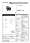
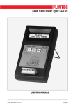
Addendum
DSP56300FMAD/D
Rev. 0, 05/2002
DSP56300 Family
Manual Addendum
CONTENTS
1 Introduction ...............1
2 Non-Interruptible
Code Sequence ..........1
3 Stack Extension
Definition...................2
4 Operating Mode
Register Bit 11
Definition...................2
5 System Stack
Configuration and
Operation Registers ..2
6 PLL and Clock
Generator ..................2
7 Design Guidelines for
Ripple and PCAP ......3
8 External Memory
Interface (Port A) ......3
9 DRAM Support ..........6
10 Bus Control Register .6
11 DRAM Control
Register .....................6
12 INSERT Instruction
Example.....................6
1
Introduction
This document provides updated information for revision 3.0 of the DSP56300 Family Manual
(DSP56300FM/AD). The updates include the following:
• Change in required instructions to ensure that no maskable interrupts occur during a non-interruptible
code sequence
• Modified stack extension description
• Modified system stack description
• Added note about the DSP56321 DPLL and clock modules
• Modified figure for the PLL filter circuit
• Modified Port A descriptions
• Added note about DRAM support
• Clarified BLH bit description
• Added note for the DRAM control register
• Modified X0 register description example for INSERT instruction
2
Non-Interruptible Code Sequence
Area to Change
Change Description
Section 2.3.2, p. 2-17 • There is a change in the number of prior instructions required to ensure that
non-interruptible code runs correctly. Replace the second sentence from the top of the
page with the following:
Due to pipeline latency, any changes to IPL masking in the SR are not reflected in code
processing until 15 clock cycles after the change is made. Therefore, after any change in
IPL masking, particularly if the masking level is increased, add 15 NOP instructions
immediately after the instruction that writes the new IPL masking to ensure proper
operation.
Note:
The two preferable scenarios in which interrupt disabling should not require
additional precautions are:
•
Within an ISR of the same or higher interrupt priority, if you are sure that an
interrupt of the same priority will not occur.
•
During background processing, but only when you are sure that no interrupt
will occur, such as during the time before the interrupt source is initialized.
Stack Extension Definition
3
4
Stack Extension Definition
Area to Change
Change Description
Section 4.3.2, p. 4-5
• Replace the first two sentences with the following:
The stack extension is in an area in internal memory (extending the hardware stack, thus
the name). The stack extension exists in either the X data memory or the Y data
memory, as selected by the XYS bit in the Operating Mode Register (OMR) (refer to
Chapter 5, Program Control Unit, for a detailed description of the OMR).
Operating Mode Register Bit 11 Definition
Area to Change
Table 5-2, p. 5-9
11
5
Change Description
• For bit 11, change the row contents to the following:
TAS
0
TA Synchronize Select
Selects the synchronization method for the input Port A pin—TA (Transfer
Acknowledge). At operating frequencies ≤ 100 MHz, you can use TA with
external synchronization with respect to CLKOUT or asynchronously (which
synchronizes the TA signal with the clock internally) depending on the setting
of the TAS bit in the Operating Mode Register (OMR). If external
synchronous mode is selected (TAS = 0), you are responsible for ensuring
that TA transitions occur synchronous to CLKOUT to ensure correct
operation. External synchronous operation is not supported above 100 MHz;
therefore, when using TA above 100 MHz, the OMR[TAS] bit must be set to
synchronize the TA signal internally with the system clock.
System Stack Configuration and Operation Registers
Area to Change
Change Description
Section 5.4.3, p. 5-19 • Two sentences in this section may create confusion about the definition of the System
Stack. A more complete definition exists on the following page. Therefore, starting on line 4,
delete the following two sentences:
The System Stack is extended in the data memory in a space specified by the stack
control registers that monitor System Stack accesses. This hardware copies the Least
Recently Used (LRU) location of the System Stack to data memory if the on-chip
hardware stack if full and brings data from data memory when the on-chip hardware
stack is empty.
6
PLL and Clock Generator
Area to Change
Chapter 6, p. 6-1
2
Change Description
• Add the following note after the chapter heading:
Note:
The DSP56321 device uses a Digital Phase-Lock Loop (DPLL) and a different clock
module than other members of the DSP56300 family. Refer to Chapter 5 of the
DSP56321 Reference Manual for details.
Design Guidelines for Ripple and PCAP
7
Design Guidelines for Ripple and PCAP
Area to Change
Figure 6-3, p. 6-11
8
Change Description
• At the top of the figure, change VCC = 5 V to VCC.
Note:
More recent versions of DSP56300 devices use lower voltage levels for VCC.
External Memory Interface (Port A)
Area to Change
Change Description
Table 9-2, p. 9-2
• Change the title for the third column to State During Reset1,2.
• Add notes that state:
Notes: 1. In the Stop state, the signal maintains the last state as follows:
• If the last state is input, the signal is an ignored input.
• If the last state is output, these lines are tri-stated internally.
However, some DSP56300 devices have internal keeper circuits that
maintain last output level even when the internal drivers are tri-stated.
Refer to the specific device technical data sheet, user’s manual, or
reference manual for details.
2. The Wait processing state does not affect the signal state.
Table 9-3, p. 9-2
• Change the title of the third column to State During Reset, Stop, or Wait.
• Change the first row of the table to the following:
AA[0–3]
Output
RAS[0–3]
Output
Tri-stated
Address Attribute—When defined as AA, these signals can be
used as chip selects or additional address lines. The default use
defines a priority scheme under which only one AA signal can be
asserted at a time. Setting the AA priority disable (APD) bit (Bit
14) of the OMR, the priority mechanism is disabled and the lines
can be used together as four external lines that can be decoded
externally into 16 chip select signals. Unlike address lines, these
lines are deasserted between external accesses. See Section
9.6.1 Address Attribute Registers (AAR[0–3]) for details.
Row Address Strobe—When defined as RAS, these signals can
be used as RAS for the DRAM interface. These signals are
tri-statable outputs with programmable polarity.
Note: DRAM access is not supported above 100 MHz. Also, the
DSP56321 does not support DRAM at any frequency.
3
External Memory Interface (Port A)
Area to Change
Change Description
Table 9-3, p. 9-3
• Change the TA signal row to the following:
Input
TA
Ignored Input
Transfer Acknowledge—If the DSP56300 device is the bus
master and there is no external bus activity, or the device is not
the bus master, the TA input is ignored. The TA input is a data
transfer acknowledge (DTACK) function that can extend an
external bus cycle indefinitely. Any number of wait states (1,
2. . .infinity) can be added to the wait states inserted by the bus
control register (BCR) by keeping TA deasserted. In typical
operation, TA is deasserted at the start of a bus cycle, asserted to
enable completion of the bus cycle, and deasserted before the
next bus cycle. The current bus cycle completes one clock period
after TA is deasserted. The number of wait states is determined
by the TA input or by the BCR, whichever is longer. The BCR sets
the minimum number of wait states in external bus cycles. In
order to use the TA functionality, the BCR must be programmed
to at least one wait state. A zero wait state access cannot be
extended by TA deassertion.
At operating frequencies ≤ 100 MHz, TA can operate
synchronously (with respect to CLKOUT) or asynchronously
depending on the setting of the TAS bit in the Operating Mode
Register (OMR). If synchronous mode is selected, the user is
responsible for ensuring that TA transitions occur synchronous to
CLKOUT to ensure correct operation. Synchronous operation is
not supported above 100 MHz and the OMR[TAS] bit must be set
to synchronize the TA signal with the internal clock.
Note:
Area to Change
Table 9-3, p. 9-3
BR
Output
Change Description
• Change the BR signal row to the following:
Reset: Output
(deasserted)
State during
Stop/Wait depends
on BCR[BRH] bit
setting:
• BRH = 0: Output,
deasserted
• BRH = 1: Maintains
last state (that is, if
asserted, remains
asserted)
4
Do not use TA while performing DRAM accesses;
otherwise, improper operation may result. Also, when
the DSP56300 device is the bus master, but TA is not
used for external bus control, TA must be pulled down
(asserted).
Bus Request—Never tri-stated. BR is asserted when the DSP requests
bus mastership. BR is deasserted when the DSP no longer needs the
bus. BR may be asserted or deasserted independent of whether the
DSP56300 family device is a bus master or not. Bus “parking” allows
bus access without asserting BR (see the descriptions of bus “parking”
in Section 9.5.3.4 and Section 9.5.3.6). The Bus Request Hold (BRH)
bit in the Bus Control Register (BCR) allows BR to be asserted under
software control, even though the DSP does not need the bus. BR is
typically sent to an external bus arbiter that controls the priority, parking,
and tenure of each master on the same external bus. BR is only affected
by DSP requests for the external bus, never for the internal bus. During
hardware reset, BR is deasserted; arbitration is reset to the bus slave
state.
External Memory Interface (Port A)
Area to Change
Table 9-3, p. 9-4
BB
Input/
Output
Change Description
• Change BB signal row to the following:
Ignored input
Bus Busy—Indicates that the bus is active. BB must be asserted and
deasserted synchronous to CLKOUT. Only after BB is deasserted can a
pending bus master become the bus master (and assert BB). Some
designs allow a bus master to keep BB asserted after ceasing bus
activity. This is called “bus parking” and allows the current bus master to
reuse the bus without re-arbitration until another device requires the bus
(see Section 9.5.3.4 and Section 9.5.3.6). Deassertion of BB uses an
“active pull-up” method (that is, BB is driven high and then released and
held high by an external pull-up resistor).
Note:
Area to Change
Table 9-3, pp. 9-4
CAS
Output
BB requires an external pull-up resistor.
Change Description
• Change the CAS signal row to the following:
Tri-stated
Column Address Strobe—When the DSP is the bus master, CAS is an
active-low output used by DRAM to strobe the column address.
Otherwise, if the Bus Mastership Enable (BME) bit in the DRAM control
register is cleared, the signal is tri-stated.
Note: DRAM access is not supported above 100 MHz. Also, the
DSP56321 does not support DRAM at any frequency.
Area to Change
Table 9-3, pp. 9-4 to
9-5
BCLK
Output
Change Description
• Change the last two rows in the table to the following:
Tri-stated
Bus Clock
When the DSP is the bus master, BCLK is active when the ATE bit in the
Operating Mode Register is set. When BCLK is active and synchronized
to CLKOUT by the internal PLL, BCLK precedes CLKOUT by one-fourth
of a clock cycle. You can use the rising edge of BCLK to sample the
address lines to determine where an internal Program memory access is
occurring.
Note: At operating frequencies above 100 MHz, this signal produces a
low-amplitude waveform that is not usable externally by other devices.
Also, the DSP56321 does not support BCLK at any frequency.
BCLK
Output
Tri-stated
Bus Clock Not
When the DSP is the bus master, BCLK is the inverse of the BCLK
signal. Otherwise, the signal is tri-stated.
Note: At operating frequencies above 100 MHz, this signal produces a
low-amplitude waveform that is not usable externally by other devices.
Also, the DSP56321 does not support BCLK at any frequency.
5
DRAM Support
9
DRAM Support
Area to Change
Section 9.2.3, p. 9-8
Change Description
• After the section heading, add the following note:
Note:
DSP56300 devices do not support the DRAM interface above 100 MHz. The
DSP56321 does not support DRAM at any frequency.
10 Bus Control Register
Area to Change
Table 9-5, p. 9-19
Change Description
• After the description for bit 22 (BLH), add the following note:
Note:
This bit is not supported by all DSP56300 devices.
11 DRAM Control Register
Area to Change
Change Description
Section 9.6.3, p. 9-21 • After the section heading, add the following note:
Note:
DSP56300 devices do not support the DRAM interface above 100 MHz. The
DSP56321 does not support DRAM at any frequency.
12 INSERT Instruction Example
6
Area to Change
Change Description
Chapter 13, p. 13-79
• For the X0 register (shown just below the middle of the page), change 47 to 23 and 24 to 0.
The correct range for the register is bits 23–0.
INSERT Instruction Example
7
HOW TO REACH US:
Information in this document is provided solely to enable system and software implementers to use
USA/EUROPE/LOCATIONS NOT LISTED:
Motorola products. There are no express or implied copyright licenses granted hereunder to design
or fabricate any integrated circuits or integrated circuits based on the information in this document.
Motorola Literature Distribution;
P.O. Box 5405, Denver, Colorado 80217
1-303-675-2140 or 1-800-441-2447
JAPAN:
Motorola reserves the right to make changes without further notice to any products herein. Motorola
makes no warranty, representation or guarantee regarding the suitability of its products for any
particular purpose, nor does Motorola assume any liability arising out of the application or use of any
product or circuit, and specifically disclaims any and all liability, including without limitation
Motorola Japan Ltd.; SPS, Technical Information Center,
3-20-1, Minami-Azabu Minato-ku, Tokyo 106-8573 Japan
81-3-3440-3569
consequential or incidental damages. “Typical” parameters which may be provided in Motorola data
sheets and/or specifications can and do vary in different applications and actual performance may
vary over time. All operating parameters, including “Typicals” must be validated for each customer
ASIA/PACIFIC:
application by customer’s technical experts. Motorola does not convey any license under its patent
Motorola Semiconductors H.K. Ltd.; Silicon Harbour
Centre, 2 Dai King Street, Tai Po Industrial Estate,
Tai Po, N.T., Hong Kong
852-26668334
rights nor the rights of others. Motorola products are not designed, intended, or authorized for use as
TECHNICAL INFORMATION CENTER:
products for any such unintended or unauthorized application, Buyer shall indemnify and hold
1-800-521-6274
Motorola and its officers, employees, subsidiaries, affiliates, and distributors harmless against all
HOME PAGE:
http://www.motorola.com/semiconductors
components in systems intended for surgical implant into the body, or other applications intended to
support or sustain life, or for any other application in which the failure of the Motorola product could
create a situation where personal injury or death may occur. Should Buyer purchase or use Motorola
claims, costs, damages, and expenses, and reasonable attorney fees arising out of, directly or
indirectly, any claim of personal injury or death associated with such unintended or unauthorized use,
even if such claim alleges that Motorola was negligent regarding the design or manufacture of the part.
Motorola and the Stylized M Logo are registered in the U.S. Patent and Trademark Office. digital dna
is a trademark of Motorola, Inc. All other product or service names are the property of their respective
owners. Motorola, Inc. is an Equal Opportunity/Affirmative Action Employer.
© Motorola, Inc. 1996, 2002
DSP56300FMAD/D