1
.
.
'
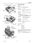
M AGTROL
DYNAMOMETER
CONTROLLER
MODE!. 46298
-..--
USER'S MANUAL
16 "0" refers to Torque.
16 "N" refers to Spe~
In order to pedorm the following it will be necessary to have a Magtrol
Dynamometer
with a test motor installed.
No computer interface or digital torque-speed readout equipment as necessary. Two
cables are required to interconnect the 4629B and the dynamometer:
LJ 14 pin/14 pin Instrumentation Ribbon Connector Cable.
D 2 pin Dynamometer Brake Power Cable.
Your Dynamometer User's Manual Chapter I, shows the interconnectiondetails.
OPERATIONAL
CHECK
Before the unit as turned ON, with the line cord and dynamometer
inter-connection cables installed, set up the unit as foUows:
o
e
.
o
Set the Dynamometer BRAKE (right side) switcb OFF.
Adjust both the TOROUE and SPEED potentiometers full CCW.
Adjust the ST ABIUTY control to approximately 10 o'clock.
Turn ON the POWER SWITCH (left side).
. Start the test motor allow a few seconds for the speed to stabilize.
Ct Flip the BRAKE switch ON.
e Rotate the SPEED control CW slowly.
-
The DYNO BRAKE LED should gOOD,the dynamometer should load
the test motor, indicated by an audible decrease in spe~
e Rotate the SPEED control off. (CCW)
. Remove the power to the test motor.
With the BRAKE switch still 00, the froot panel LED's should display
as fonows:
DYNO
BRAKE
GPIB ERROR
1-2
OFF
OFF
-
1
I
GPIB TRANSFER
SPEED SYNC
AUTO RANGE
GPIB TORQUE
GPIB SPEED
CTLS ACTIVE
]
]
OFF
OFF
ON
OFF
OFF
ON
Switch the BRAKESwitch OFF, and the AUTO RANGE LED should
go OFF.
]
I£the above checks out satisfactorily, it may be assumed tbat the 46298
has survived shipping. accepts the dynamometer/motor combination
and is working satisfactorily.
]
MODEL 4829B CAPABIUTIES:
]
This unit is a computer interfaced speed controUed power supply. It
is designed to conleol any Magtlol Load Ceu Dynamometer from any
type of computer incorporating the IEEE-488 instrument controUer.
]
]
]
J
J
J
J
I
la addition to control. ODcommand, it will return current TorqueSpeed data lathe computer. The unit may be used without a computer,
bowever it will function at only a fractioD of its capability, and a
Magtrol digital readout device will be required to disp1ay torque and
speed.
In a computer controUed environment, tbe following motor te.sting
capabilities are available:
a Torque(O) Vs Spced(N) data acquisition at a rate of 10 readings
per second.
CJ Automatic Q-N continuous (progressive) loading in either a decreasing or increasing speed mode.
DCapability of removing the EFFECTS OF INERTIA
obtained dynamically. See Appendix B.
o Either Q (torque)
-from the data
or N (speed) programmable test points.
1-'
[
o
I
C) Complete curve capability for most types of motors. This includes
single/poly phase induction. ACIDC series, PMDC, Brushless DC, air
and (suitably coupled) internal combustion.
I
Data storage (Don-volatile) within the 4629B of up to 500 Q-N tcst
points.
Please note:
and 60 RPM
programmed
and stepper
Speed mode, closed loop control, between locked rotor
may be erratic, depending on the test motor. Therefore,
loading (in the speed mode) for very low speed gear.head
motors may not be possible.
(
(I
(,
(,
( I
(,
[
[
[
[
[
1.4
r
]
]
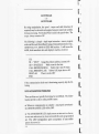
2. Installation
I
]
I
=-~ ~
="""""
0"'0"0
I
J
.
~[g]
Please be sure that the computer and the 46298 are botb turned OFF
when you install the GPIB connector cable.
Uyau have completed the equipment check.out as outlined in Chapter
I, the 46298 Dynamometer interconnection is complete. If an optional Magtrol Digital Readout is to be interfaced with the unit. it will
be necessary to bave a Magtrol7 Pin DIN to 14 pin Ribbon Connector
Cable. This Cable assembly is Magtrol P.N. 88CS09 and in stock at the
factory. If a readout was supplied with the 4629B, the cable will be
included. Please refcr to Page 1-2 of your Dynamometer User's Man.
uaI for interconnectioD details.
-
J
J
J
J
J
,r
,
I
r
,f
.r
.
r
Although there are numerous computer interfacing melhods, all Magtrol electronic instuments use the IEEE-488 (GPm) Standard for the
foUowing reaons:
.. GPm byte parallel is inherently faster than serial interfaces.
..In motor testing, at least five separate parameters must be synchronized. A system of easy, fast access to morc than onc instrumcnt is
essential. With thc GPIS, up to 15 instrumcnts may be accessed OD
ODCport.
... The
GPIB has rigid data formatting and hardwarc standards. This
increases the chances for things to work when the hardware/software
is installed.
GPIB
- COMPUTER
INSTAUATION
On most computers, the GPID interface is not a standard item. An
intcrface card must be installed and the driver software made resident
on disc. Thcre arc several manufacturers ofthesc products, and some
'.1
r.
systems exchange data more rapidly than others. In motor tcsting, the
tcst rate and speed of data acquisition is very important. One rccom.
mendatioo, isNationaI Instruments Corp., PN GPIB.PC2A, for IBMaD
compatible PC's. Additionally, it will be necessary to install a IEEE488 Cable between the computer and the 4629B.
I.
SOFTWARE INSTAUATION
I.
There are usually a number of formauing questions to be answered
during the GPIS software installation. The foUowing items pertain to
the 4629B.
All GPIB data acquisirioD systems require the use
Codes fCf"CR of data termination characters. The 4629B uti.
BAS" >£x 000
lizes the Hewleu Packard HPlB standard tenni. rn. o-R$(13!'" "
~1010A 10
LF'
nation characters "Carriage Return (CR)-Line
Feed (LF)" (in that order), looking for these symbols to terminate
communication.
There may be another programming setup requirement relating to a
communication fault delay timeout, in order to alleviate a computer
hang-up. Do not set this period too short,leave at least one second. If
the computer resets the interface premature1y,the host instrument can
hang.up waiting for the n ever-ta-happen
"CR.LF."
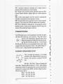
CCCE S'MTCH
-.
12345 coo.
00000 ,
PRIMARY ADDRESS
10000
01ee0
All instruments serviced on the GPIB have a separate
11e00
primary address code. 0 n the rear pane~ next to the
00100
GPID connector, there is an opening providing access
10100
to the code selection switch. Tbe default setting 01100
(from the factory) on
, 2 , , 5_lfJ 7 8 11100
00010
the 4629B is nine 1
_10010
(09). If you wish to
~:o 0 0
01e10
iii
",,""'"
change the code, the
11e10
00110
chart will help in obtamm g the setting you want.
10110
~S8
is to the right. Switch
Please note that the M
~01110
segment identification resulted iD the binary code
11110
00001
notation reversed from the standard convention
..
'-2
~~~0
1
2
3
.
,
,
,
,
,
"
"
"..
..
L
t,
I~
I~
t,
r "'I
('
"'I
('
"'I
('
,
r,
r,
r'
1
]
]
]
]
]
]
]
]
where thc LSB is normally on the right.
Some PC interfaces (National GPIB-PC2A) will access 1 to 15 (4 Bit)
primary address numbers only. Others. may access up to 31 (5 Bit)
codes; even though the GPIS capability is limited to 15 instruments.
The 46298 Primary Address uses the 5 bit format. Before selecting a
value greater than 15, check with your particular interface's primary
address code range capability.
DATA ACQUISITION
When the systems are interconn~ed.
the rust thing you might want to
verify is that the 46298 and host computer are communicating.
The 46298 requires DO specific input instruction in order to output
immediate torque and speed data. Simply follow your Computer/GPIS interface instructions, and issue a data input or read
comrn,nd. H your primary address is set and addressed correctly, the
46298 will respond. It \WI probably be necessary to dimension your
input variable to 15, ie; 13 characters plus CR-LF.
Speed-Torque data is a fixed length string, AScn format, floating
piont decimal. structured as follows:
SdddddTdddd.L
]
]
]
]
]
1
Decimal digit, 0 thru 9. "5" indicating that the fonowing5
Where d
"'"
digits are RPM, '7" indicating that the neX14 digits + D.P., is Torque.
The last character, (shown "L") may be eithor "L" or "R". "L" =
CCW dynamometer torque application, "R" "" CWo
The decimal point location willdepend upon the sp~cdynamometer
and torque range in use. The CR.LF are symbolicand willnot display.
For example; suppose a motor is running at 1725 RPM cloclcwisc, with
the dynamometer loading the motor 10 22.6 OZ.In. The 46298 will
transmit:
,.,
r ,
['
,
S017ZSTOU.6R
-or-
['
SOl715I'22.60R
-
By string manipulation. the speed
torque and shaft direction (if
required) may be extracted and assigned separate numerical variables
for data processing. No Decimal Point is used in the speed value. The
torque always contains a DP.
-
The following is a simple single input instruction
- source program
written in Microsoft Quick Basic~ using aNatiooal Instruments Corp.,
GPm.PCIlA. P.N. 320043-01 lEEE-488 Interface. It will access the
46298, fetch immediate data and display it exactly as received.
C1.S
N$ "DEV9~ 'Assign tbe primary address, (assume) 09.
""
'Make room for the data.
rdS SPACE$(lS)
CALL IBFIND(N$. BD%)
'Subrto Call-loi.. Pri Addr.
CALL IBRD(BD%. rdS) 'Subrtn Call, Input data to rdS
PRINT rdS
'Place it on tbe CRT
END
-
If tbe communication
lowing.
DATA ACQUISmON
chcck-out is functioning properly, skip the fol-
['
['
1
,
[' ,
t
t
t
(
PROBLEMS
These problems are typica1Jy frustrating, but not difficult. The following may provide a clue to some possible causes.
... Whenever communication is complete
tbe GPIB TRANSFER LED will be OFF.
- and properly tenninated -
go The GPIB ERROR LED simply means an instruction cbaracter was Dot understood, ie; does not match the units programmed
set Tbe LED extinguishes upon acceptance of any subsequent cbaracter(s).
'.4
,
(
r,
r,
l
(
1
I
I
I
J
J
.J
qo
If GPIB TRANSFER LED remains ON, this would indicate that
communication has occWTedbut the computer either has Dot accepted
the data (probably the CR-LF) or otberwise has not released the bus
. for some reason. Check your interface instaUatioo software instructions.
The 46298 will probably be "hung up." You must turn the maiD power
switch OFF (left side), wait afew seconds, then ON again to reestablish
operation. The only time that the GPID TRANSFER LED will remain
ON. in proper operation. is when your program contains a continuous
loop and communication runs uninterrupted.
Q" If the GPIS TRANSFER LED is off, repeat the data acquisition
instruction, only keep an eye on the LED to see if it flashes. If it does
Dot, look for a primary address or interface hardware problem. If it
flashed ON then OFF;
you~ very close. recheck your program,
especially how you handle the input variable.
-
You may save time by contacting Magtrol Customer Service; ask for
GPIB software assistance.
J
]
]
]
]
]
]
1
,.,
1
]
]
]
]
]
]
]
]
]
]
]
]
]
,
-~I
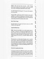
3. Instruction
Set
=E!!'E33
-~
Before proceeding with the instruction set. to avoid look-ahead type
of references" some fundamental operating principles should be covered.
DYNAMOMET£R CONmOL
MODES
Dynamometer torque load is applied to a test motor by either of two
modes of operation:
1. Direct torque control. where regulated and fixed current is applied
to the Dynamometer Hysteresis Brake.
2. Speed control,. where the immediate value of speed is compared to
a reference, and brake current is proportioned to tbe difference.
In the speed mode (2), the Dynamometer/4629B, becomes a closed
loop system forcing the test motor to operate at a fixed speed. Two
digital to analog converters form an integral part of this function.
controlled by the system microprocessor. For reference within this
manual, these elements are ideotified as Q-D/A for torque and N-D/A
for the speed digital to analog control elements.
SPEED CONmOL
RANGING
It is necessary to prcgram the 46298 with the test motor's maximum
RPM to establish the speed range value. This is required because of
the 9ti.de range of motor operating speeds accommodated. There are
two methods available for accomplishing this:
1. NOD-Instructed.: U the following three conditions are met. the unit
will establish the correct RPM operating range automatically.
3.1
C'
.
o No previous GPIB SPEED range instruction.
o BRAKE sw;tch OFF.
o Test motor installed - and running . with the Dyna'
[I
shaft spwJ
above 256 RPM.
[l
The 4629B will assume the current RPM talue to be the free-run motor
speed, and will select and retain the correct speed range. The acceptance will be signaled by the AUTO RANGE LED going ON.
-
Z. GPIB SpeciOed: This method. of range control has precedence, and
the instruction suspends the AUTO RANGE function desaibed
above. To recover the AUTO RANGE capability, refer to the "R" or
an "N" instruction.
"Set An Operating Speed Range" is described
below.
MODEL 4629B INsmUCTlON
[,
[,
L
SET
Following is a condensed listing of the control characters recognized
L
by the 4629B in alphabetical order. The characters dddd represent
~
a variable numerical value following the identifier. Leading zeros are
not required.
A
B
C
o
E
Fddddd
H
HS
Idddd
M
M1
MO
N
Nddddd
o
PDdd
PUdd
PDddS
PUddS
PR
3.'
l
a
Odddd
R
S
X
Y
Z
All characters must be in uppercase and AScn format. All cntries
must end with a CR.LF (Hex OD-OA), as prcviously outlined in the
GPIB Computer Installation. Section 2. U a string or charactcr is not
recognized the GPIB ERROR LED will go ON, Tbe BRROR LED
will reset OFF upon a valid instructioD.
-
l
l
l
l
l
l
l
./
I
I
I
)
)
)
)
)
Set ADOperaU..
Speed Roall"'
-
A 2,000RPM
B-4,OOORPM
C = 8.000 RPM
D-16,000RPM
E -32,000 RPM
Fddddd Where ddddd is a specified speed range value between 256
and 32,000 RPM. and the motor speed is not to exceed. Leading zeros
are Dot required. The AUTO RANGE LED will go OFF with any of
the above ruge values when accepted.
-
Speed Testpolah
Nddddd Where ddddd is any value up to 32,000 RPM. Leading zeros
are not required.
Example: Force the motor to operate at 1787 RPM. Enter: Nt7S7
(CR-LF).
The GPIB SPEED LED and SPEED SYNC LED go ON; the motor
will decelerate (with some overshoot) to 1787 RPM. The SPEED
SYNC LED may be somewhat intermittent. refer to Chapter 4, Para.,
STABILITY CONTROL.
J
Note: U the BRAKE switch is On', the DYNO BRAKE LED will
flash ON~FF-ON. signaling the inability to comply with the instruction. until the brake switch is set ON.
J
Resd From GPIB Speed Control:
.J
]
]
...
N (only) Sets GPm SPEED LED off, resets the 46298 to the highest
speed range, enabling the AUTO RANGE capability.
Torque Testpolnt:
In the foUawing.the actual torque values selected (dddd) must be
within tbe capability of the dynamometer in use. This value, (fuUscale
rating) is shown on the dynamometer front panel.
3.3
QdcLdd Where, the torque value, in any units
= dd.dd.
F10ating
point notation, leading zeros arc not required but the value entered
must contain a decimal point (d.ddd, dd.dd, ddd.d or dddd).
-
The GPIB TORQUE
the value specified.
LED will go ON. The motor will be loaded to
Example: Q3Z.s Load the motor with 32.5 of whatever torque unit is
applicable, as specified on the dynamometer front panel, ie; OZ.IN.,
GM.CM., mNm. etc. Ifthe BRAKE switch is off, the DYNO BRAKE
LED will flash ON-OFF-ON until the switch is closed.
Reset To Zero Torque:
Q (only) Removes the torque
TORQUE LED will go OFF.
load from the motor, the GPIB
Apply Fixed Brake Power:
Idddd Numerical value (dddd), to be any whole number between 1
and 4095, is converted to 12 bit binary and applied directly to the
Q-D/A converter. Do not use a decimal point. This results in a fixed
application of voltage (and torque) on the Dyna' brake. Tbe value
(dddd) translates to 0 to 28 V.D.C. The GPffi TORQUE LED will
goON.
This instruction is a very fast method of loading a motor to a specific
value of torque. However the value (dddd) must be predetermined.
There will be long term torque drift (subject to effects of bysteresis
brake beating) since the function is open-loop. In the progrllmming
examples of AppendixA, a method for establishing an Idddd to Torque
Calibration is shown.
Provide The Immediate Q-DlA Value:
X This entry instructs tbe 4629B tbat upon the next computerreadl4629B-write funccion; instead of CWTentSpeed-Torque data, the
contents of the Q-D/A converter be returned. The number rctwucd
will be the decimal equivalent of the binary 12 bit Q-D/A word. This
3.4
.,.J
,
rJ
,
'.,
..
.I
I
I
I
I
I
I
]
]
]
ioformaUOD is useful when establishiDg a correct Idddd instruction.
After the single data write instruction, the unit automatically resets to
provide standard speed-torque data 00 subsequent write (data output)
instructions. See Appendix A for further. information.
Apply FIxed Speed:
Zdddd dddd is converted to a 12 bit binary value, and applied directly
to the speed N~D/A converter. The value of dddd must be from 0 to
4095. For this instrUctiOD to work properly, the speed range A thru F
must have been previously output.
This instruction is a very fast method of loading a motor to a specific
value of speed. However the value (dddd) must be predetermined. In
the progr~mming examples of Appendix A, a method for establishing
a Zdddd to speed value is shown.
Provide no CUlTeDt N.DlA Value:
Y This entry instructs the 4629B that upon the next computer read
cycle, instead of speed-torque data. tbe contents of the N-D/A converter be returned. This informatioD is useful when establishing a
corred: Zdddd instruction. After the single data write instruction, the
46298 automatically resets to provide standard speed-torque data on
subsequent write (data output) instructions. Appendix A contains
additional information.
Programmed Load Testing:
]
.J
J
J
.,
PDdd Program down (speed mode) from free-run to locked rotor at
a rate proportional to dd. Where: dd is any number from 1 to 99,
relating indUecdy to RPM per second where 1 is the slowest
-99 the
fastest. The SPEED SYNC LED goes ON if the instruction is accepted.
The absolute rate of speed decrease, or test time, is dependent upon
the free run speed of the test motor, and the speed range setting.
Therefore, the rale specified by "dd" must be established by test.
M'
Try 20 to start with
-then adjust up or down from there.
3.'
[
Prior to thc instruction, if thc speed range informatioo was not estab-lished, the GPW ERROR LED will go ON indicating failure of the
instruction to execute. To correct, command an "A thruF' instruction.
Please note: As a rule; eUher the AUTO RANGE LED or the GPW
SPEED LED must be ON, indicating that a speed control range has
been specified, in order for a "PDdd" instruction to execute.
[
I
I
PUdd Program Up at a rate of dd, same as "PDdd" except thai the
RPM is increasing. To be accepted, this instruction must have been
preceded by an N or PO instruction.
I
PDddS or PUddS Same as "PDdd.PUdd above," except that up to
500 blocks of Speed. Torque data is stored within the 4629B memory
for future retrieval. This releases the host computer for other process.
ins as a test is taking place.
I,
In order not to overrun the memory, the total 'test time must be
maintained UDder 4S seconds. As long as the memory is not overrun,
multiple PD/PU(S) instructioDS will accu.m.ulale. See "0" command
and Appendix A for further information.
I,
I,
Cancel PD/PU Routine:
PR Resets to free run speed from a PD/PU instruction. providing the
shaft is still rotating. The currcnt speed range status is retained. If
Ihere was a previous "Nddddd" instruction, the unit will return to that.
Please note thallhe PR instruction will fail, resulting in a locked rotor
condition, if the shaft speed was below tOORPM when the instruction
was issued.
I~
1~
1..
Retrieve Memory Data:
o (DOlzero) This entry instructs the 4629B to output the contents of
memory obtained from a previous PDddS or PUddS function. After
an "0" instruction is received, upon the next computer read cycle"
instead of currcnt Q.N data, there will be 6000 bytes of data plus
CR.LF from memory. Dimension the input variable 10 6002.
'.6
1,,"
1...
1~
1..
]
I
I
I
I
I
I
I
I
I
I
I
I
I
1
Data in memory is retained indefmitely even if the 4629B is switched
OFF. The memory is automatically, and only erased after a successful
"0" command has been executed.
Appendix A provides a programming example.
Set Standard Resolution:
S All torque data will be formatted. and fIXed..to exactly the resolution
of the dynamometer front panel torque identification.
Set Hlgb Resolution:
H FIXes the torque resolution from that shown on the dynamometer
front panel. by an additional 112 IS digit (0-2-4-6-8), but Dot greater
than 1 part in 9999 resolution.
Set Automatic: resolution control:
us Allows the torque value to increase reso1utioDby 10 automatically. The D.P. will shift right or left one digit to maintain at least 1
part in 2(XX)resolutioD. This is tbe default mode ofoperation (at power
up).
Manual CODtrois 00:
MO (M zero) Disables the manual TORQUE and SPEED controls.
The cn..s LED will extinguish. The STABIUTY control is not
affected.
Manual Controls On:
Ml Enables the TORQUE and SPEED controls. The cn.s LED
will go ON.
M (only) Toggle the front panel controls, ie; ODif Off -OffifOD.
Reset All:
R Restores the unit to power up state. Clear all previous instructions.
'.7
1
]
4. Controls, LEDS and I/O
I
I
I
I
I
I
I
I
.1
J
.J
,J
J
1
I
This chapter desaibes the front panel controls, LED indications and
rear panel Input/Output connector details.
CONTROL POTENTIOMETERS
TORQUE: This is an open loop, general purpose control for applying
torque to a test motor, essentially independent of speed. This ten turn
potentiometer applies regulated current to the dynamometer hysteresis brake. up to .7 Amps. A hall turn ODthe control may be necessary
before the brake responds. Total rotation of the control, to obtain
maximum dynamometer torque, varies depending upon the Model
Dynamometer in use.
SPEED: This control mode is a closed loop system. where the 46298
automatically adjusts the dynamometer torque, such that a test motor
is forced to operate at a fIXed speed. This control method permits full
performance data through the unstable (below the knee) region of
induction motor operation.
There is a special requirement for speed control, necessitating that the
free run RPM must be programmed in memory, (within tbe 46298) to
establish an overall operating range. As a general rule, before speed
control may be used. either the GPm SPEED LED or the AUTO
RANGE LED must be ON.
When the 4629B is first turned on, it defaults to the 32,(0) RPM
(maximum) range. Without speed ranging - for example; if one at.
tempted to speed control a 60Hz 4 pole induction motor on this range,
it would be necessary to rotate the 10twn SPEED control potentiometer 9 213turns before anything happened!
The following procedure will establish the speed range by activating
<-,
r
the AUTO RANGE capability. The GPIB SPEED LED must be OFF
for the AUTO RANGE to function. That means that no prior GPIB
inst1UCtedrange information can be in effect. An "N" or "R" instruction will clear GPffi entered range information.
With the TORQUE and SPEED controls set full CCW:
Turn the BRAKE switch OFF.
Start the test motor, allow a few seconds.
Turn the BRAKE switch ON.
o
o
o
The AUTO RANGE LED will go ON, indicating that an operating
speed range is established. As long as the brake switch remains ON,
the established speed range will remain in effect. If the shaft RPM
attempts to rise above this value, restraining torque will automatically
apply.
Since the SPEED Control Potentiometer operates from free run speed
down to a few RPM's, locked rotor torque may require application of
some TORQUE Control.
This (single turn) control is required because of the range of motordynamometer combinations possible. If the response-gain characteristics of the system are such that instability oCcurs, speed-torque
oscillations may result.
This control provides damping, by proportioning a rate-feedback signal in the speed control system. It only functions in the SPEED control
mode.
Magtrol
r,
['
,
r:
[,
[,
[,
[.
oontrol, start with the
ocontrol
For Magtro) Models IID-I06 and HD-l00, set the STABILITY
to a position between 11 and 12 o'clock.
o For
[,
[,
STABILIT\' CONTROL
If you have not "fine tuned" the STABIUTY
foUowing.
L
[,.
[,
Models HD-400, HD-SOO and HD- 700 use a setting of
10 to 11 o'clock.
4.'
r
J
]
C1
For Magtrol Models HD-70S, HD-800 and HD-8OS use a setting of
9 to 10 o'clock.
]
]
]
]
]
]
Since the type of test motor may influence stability, slight (118 turn)
adjustments from the above recommended settings may enhance stability and data consistency. Another method to "fine tune" this control
is to output a Nddddd instructiop, then slowly adjust the STABIUTY
control for best response and continuity of tbe SPEED SYNC LED.
Please Dote: Excessive CW positioning of the control will produce slow
response, ie; "sluggishness." and "speed hunting" of the system. Conversely, insufficient signal typically results in dynamometer instability
with torque-speed oscillations, usually more pronounced in unstable
regions of induction motor operation. Please be very carefuU here, an
unstable system can become spectacular!
LED INDICATORS
The foUawing is a detailed explanation of the front panel LED functiODS.
DYNO BRAKE
- This is a red color LED indicator that goes ON
-or is calling for -torque,
]
anytime
]
BRAKE switch is closed. torque. possibly full
applied; sometimes with violent results.
]
Another function of the DYNO BRAKE LED is to signal a GPID
instruction incapability. For example, if a speed or torque instruction
]
]
]
the dynamometer
has
regardless of
tbe BRAKE switch position. With the BRAKE switch OFF this
indication serves as notice (or warning) 10 the operator, that if the
- will be
instantly
is transmittec!, with the BRAKE switch OFF, this LED will flash on .
off - on until the BRAKE switch is twned ON.
GPIB ERROR - Anytime an unrecognizable instruction character is
received by the4629B, the unil will set this red LED ON. Additionally,
if a "PD" or "PU" type of instruction is entered without previously
establishing range information, the GPIS ERROR LED wiD go ON.
Any valid instruction received after the LED is ON will clear the error
indication.
'-3
1
[
-
GPIB TRANSFER While the4629B is eltherreccivingor scDdingdata
this amber co10r LED in turned ON. It remainsOD for 112second after
GPIB cessation of activity.
If the 46298 or bost computer should "bang.up," and this LED
remains on., it serves as an indication that a GPIB communication
transfer was incomplete. Lookfor amissing CR.LFfrom the computer
to4629B, early computer sign.off or otber software or bardwaredefect.
There is more on this in SOFTWARE INSTALLAll0N Chapter 2.
-
SPEED SYNC When this amber LED is ON; the shaft RPM is within
a few RPM's of an "Nddddd" specified value, or a PU/PD instruction
is accepted. and in progress.
AUI'O RANGE - This green LED signals that the 4629B bas set the
free run speed of the test motor automatically. If the speed range is
GPm specified, tben tbe AUTO RANGE LED is OFF.
GPIB TORQUE. This green LED signals that the unit is presently
operating under a computer directed torque control mode of operation. The "Q" or "I" type of instruction sets this mode. If the manual
TORQUE control is active it can over ride the GPm instruction.
-
GPIB SPEED This green LED signals that the unit is under a
computer directed speed control mode, and tharthe operating speed
range is established All "A tbm F' or "N," type of instructi0D5will
turn this LED ON. AUTO RANGE control is disabled, regardJcss of
the brake switch setting. If the Manual SPEED control is active it can
over ride the tbe GPIB instruction.
en.<> ACTIVE - TIlls greeo LED signals that the unit will a=p!
manual TORQUE and SPEED control. If the TORQUE and SPEED
controls are de-activated by a GPIS instruction "MO" the CTLS
ACTIVE LED will be off.
C.
L
L
[
[
[
[
[
[
[
[
[
[
.-.
r
1
]
]
]
]
]
]
]
4828B ELECTRICAL ~O
Following is a description
of the electrical Input/Output.
All connectors are
contained on the rear panel
of the 4629B.
GPIB INTERFACE
Computer to instrument interconnection uses the standard 1EEE-488
Instrument Cable available &om instrumentation cable manufacturers,
computer hardware outlets, Magtrollnc.. or Hewlett Packard dealers.
It is normally supplied with the IEEE-488 computer interface hardware.
Following is a brief description of the interface lines. For morc thorough information, there arc various publications on the IEEE-488 from
I"e~Moto,oIa,IEEE,NatWna1
Semiconductor and Hewlett
Packard to name a few. Two
bytes form the composition of
the GPmi 8 bits for data transfer, and 8 bits for interface 000trol.
-
]
]
Dl
]
.J
J
]
. DB .
are the data
signal
lines. The data format is 8 bit
ASCD.
DAC,
RFD,
DAV _ are
byte
- Ready For
01 8113_
D2 _214_
05
D6
D3 _315_
04 _416_
oe
Data, goes
07
EO! 8517_
REN
DAV _ 6 IS_
DAV-COM
tlFRO_
NFRD-COM
7 !9_
t()AC _ e 20_
IFe _ 9 :11_
SRQ - 1022_
transfer lines.
DD
IEEE-488
INTERFACE
ATN _
11 23_
SHELD_ 12:J4_
ND C-COM
Fe-COM
SFlO--COM
A TN-CONI
SIGNAL
GRO\.U)
passively high.
DAV - Data Valid, an instnuneot may signal that its data is valid, by
puIJiJIg ,his line low.
DAC. will go passively high, $igJIAling that the: data has been accc:pted.
ATN, IFC, SRQ, EOI, REN - are the bus management lines that
coDtrolthe:ordcrlymovement OfinfonnatiODacross the interface liDes.
4.'
1
.
L
-
(attention) monitored continually, and a change results in
activation o( the transmit/receive control signals.
lFe - interface clear, used by the system controller to place the GPIA
(General Purpose Interface Adapter chip) into a known quiescent
state.
SRQ - service request signals a need (or service by requesting the
controller to interrupt the current sequence of events.
REN - Remote Enable selects an allernate source for device programming data. This converts the GPIA into another state of operation.
EO] - End or Identify has a dual purpose. It may signal the end of a
multibyt:etransfer, or when used in conjunction with ATN places the
contents of the parallel poll register on the bus.
[
DYNAMOMETER
L
ATN
BRAKE
The 46298 applies power to the dynamometer load brake through a
cable fiued with Cinch type, 2 pin connectors. These lines connect
directly to the dynamometer hysteresis brake coil in
- II
MagtTol Dynamometer Models HD-lOO, HD-I06, HD400, HD-SOO,HD-700 and RD.705. On the Models
HD-800 and HD-805 there is an intermediate booster power supply
contained within the dynamometer cabinet. The applied voltage is 02S VDC, at up to .7 amps dependant upon dynamometer size.
CG +
This is an output only connector. It is (or input
provision to other Magtrol Digital Torque-Speed
products. The connector is a standard 7 Pin DIN
type.
D.P. Pin 7, D.P. Pin 3: These are decimal point
locator lines. They have pull-up resistors to + 5 VDC. Eachindividual
dynamometer will have tbe appropriate line connected to ground that
ddd.d
- Pin 7 HI,
-
- and
L
[I
[\
[I
[
[.
other Magtrol products.
Pin 3 m.
dd.dd
Pin 7 LO, Pin 3 HI.
d.ddd - Pin 7 HI, Pin 3 LO.
.-.
L
[I
ACCESSORY TORQUE-SPEED OUTPUT
codes the D.P.locatioD for the 46298
The D.P. locator code is:
L
.
-
l]
]
]
]
]
]
]
]
Tachometer signal: This is a TIL compatible frequency output of 60
pulst5 per shaft revolutioD. The tachometer common is chassis
ground
Torque Output: This is a bipolar analog voltage. The torque common
is chassis ground. The torque s4;nal amplitude varies witb the individual dynamolOeter connected to tbe 4629B. It is equal to the whole
number of the torque value, (identified on the dynamometer front
panel), in millivolts. Positive polarity would be indicative of torque
applied in CW direction of rotatioo. For example; for a HD- 700-6with
full scale torque applicd in a CWdirectiOD; Torque
425.0zJn..and
.425 Volts between pins 4 and 2. with pin 2 positive.
-
ACCESSORY
CABLE
~---
The cord set required to interconnect the 46298 to another
Magtral Digital Readout is
.
Magtrol P.N. 88CS09. This has
a 7 pin DIN connector on ODe
""
C<HC'T'O_ cnd. with a 14 Pin ribbon con::::::.=
nector OD the other.
Do not
use this cord set to interconnect a dynamometer to the 46298. No
,--
."..
"
damage will result ~ but nothing will workl
DYNAMOMETER
]
]
]
]
]
This is a 14Pin ribbon connector. interconncctiag the 46298 and any Magtrol dyaamomcter.
Pia 11. Tach supply + 9VDC is a filtered
bias voltage for the Tachometer Photo Cell.
The actual voltage on this pin is Dotcritical
and may be anywhere from +9 to + 12V.
referenced to pin 8.
~-
<X:H«TOO:lHELt.1'H>
Pin 10 is the tachometer frequency signal providing 60 pulses per shaft
revolutioD. The signal1evel has a low voltage of.2 ;t.1 and a signal
high of 1.0 :t:.2 VDC. The common to this signal is Pin 8.
..,
]
.
I
Pin 14 is the torque signal. referenced toPin 13. This is a bipolar analog
voltage. Pin 13 (common) is chassis ground. The torque signal amplitude varies with the individual dynamometer connected to the 4629B.
It is equal to the whole number of the torque value, (identified on the
dynamometer front panel), in millivolts. Positive polarity would be
indicative of torque applied in CW direction of rotation.
For example; an HD-IQ6..6 with full scale torque applied in a CCW
direction; Torque... 2.50 Qz.lD. - -.250 Volts between pins 14 and
13, with pin 14 negative.
PIlI 9. Pin 12: These are decimal point locator lines. Each individual
dynamometer will have the appropriate line connected to ground that
codes the D.P. location for the 4629B and other Magtrol products.
The D.P. locator code is:
-
ddd.d
"'"
Pin9 N/C, Pin 12N/C.
dd.dd
Pin 9 LO. Pin UN/C.
d.ddd - Pin 9 N/C. Pin 12LO.
Where, N/C no connection, LQ
Common to Pin 8
-
-
Pin 7 is 5.0 VDC for the Photo Ceu Lamp. It references common to
pin 8 as shown.
Pins J...4and S-6 are 20 VDC isolated instrumentation voltages for the
torque signal amplifiers and the torque load ceU power supply. Within
the dynamometer inclosure, these unregulated voltages arc converted
to regulatede ::I:1SVDC. and (adjustable) 6-8 VDC for the dynamom.
eter torque transducer load ceU. Your Dynamometer User's Manual
Chapter 4, covers this in greater detail.
[
[
[
L
L
[
r,
['
,
t
t
,-,
l
"T'
,
.,
l
1
)
)
-EJ
-
~I _I
]
]
]
]
]
]
u
'--'
s. Calibration
I
-
'II 10
........
0
0
I
I
There are calibration and balancing controls for most of the analog
elements in the 4629B. Normally, DOadjustment of these elements is
anticipated for the life of the instrument. However, all or part of the
calibration and balancing procedures may be indicated if any of the
following conditions exist:
ib Slight torque loading
-with the DYNO
BRAKE LED ON, when
not called/or.
b A torque difference between the GPW indicated value and another
Magtrol Digital Readout of greater than ~.2S%
ib A torque difference between CW and CCW full scale readings. of
greater than 2 least significant digits. in standard resolution.
There is no calibration for the digital speed reading. Please refer to
MODEL 46298 SPECIFICATIONS in this chapter.
]
]
]
]
]
-,
Routine Torque calibraliOD and zero offset adjustments should always
be done on the Dynamometer. The torque signal offset and calibration
C()Dtrols within the 46298 are there to permit standardization with
other Magtrol Digital Readout.&, as well as agreement between full
scale values in both CW and CCW directions.
The torque value produced by the dynamometer should read within
tolerance on all instrument.&.If adis(.imilaritycxist&between the 46298
and another digital readout, before proceeding with zero offset or
calibration adjustment it willbe necessary to establish which of the two
instruments requirc the service adjustmcot. This must be dODCfirM,
by standardization of the dynamometer signal output.
5-1
.
WARNING! The foUowing requires removal of the 46298 top cover.
All connections and trimpot adjustments must be made only as specified herein and with caution. There is an electrical shockbazanlinside
the 4629B. Do not touch, or connect instrumentation to any elements
of the circuit boards, front panel or chassis components.
All calibration and balancing potentiometers are contained on the
circuit board identified TeC-I. This is located in the lower left corner
of the 46298 chassis, facing from the rear panel. The roUowing sketch
shows that portion of the board where the trimpots are located, their
identification and function.
[
[
[
L
L
£.
[
N ..,
o
Trimpot
0
[I
,
IundJon:
OCaI
OBai
CaJ
BaI
+CaJ
+BaI
N
MO
.
-
o
To perform
the rouowing,
\
- Accessory
-
output torque calIbration.
Accessory output torque signal zero.
r.
. cc:w
torque fuflscale calibration.
- CON torque zero.
- ON torque full scale calibration,
. ON Torque zero.
. Speed control op-amp null.
- Front panel TORQUE control zero.
- Torque (O-O/A) zero.
it will be necessary
to write a short
- contin-
uous loop - program to have the 46298 Torque output reading displayedby the controllingcomputer. All references to "CRT" in the
,-,
[,
r. .
r
Ij
r
1
]
]
following pertain to this reading. APPENDIX A contains a short
program example, CONTINUOUS Q-N DISPLAY, for your cereecnce.
TORQUE ZERO (NUll.) ADJUSTMENT
]
o Remove any couplings from the dynamometer shaft.
]
. Place a precision voltmeter reso1ving at least .1 millivolt (D.C.)
between pins 13 and 14 on the DYNAMOMETER ribbon conneaor,
pin 13 negative. You may have to remove the connector cap on tbe
cable, or obtain access from inside the dynamometer rcat panel
]
. Adjust the dynamometer zero control for best zero (dynamometer
torque signal output) on your voltmeter.
]
While observing the 4629B Output Torque Reading (CRT):
]
The object in the foUowingstep is to alternate between the - and + Bal
trimpots. until you know that each is adjusted sueb that your output
torque reading is JUST at zero. on both trimpots.
]
e Adjust the + BaI trimpot slowly try both CW and CCW rotation
]
]
]
-
until the indicated torque value reads higher, then back off very slowly
until the reading is zero, or returns to the original value. Repeat this
procedure on the.BaJ trimpot
work back and forth and set zero with
a 1 flashing occasionally.
-
FULL SCALE TORQUE CAUBRATION
o Complete
the zero adjustment procedure outlined in the preceding
paragraph. Install the Dynamometer Torque Calibration beam. as
shown in the sketch.
]
]
,.,
]
l.
.
Turn on the BRAKE switch. Rotate the TORQUE control full CW
for maximum applied torque. With a precision weight. apply a known
torque at or close to full scale, in the CCW direction. Maintain tbe
beam exactly horizontal and perfectly still
-
. Observe the voltage reading on the Voltmeter (Across Pins 13 and
14). Adjust the TORQUE CALIB, on the rear panel ofthe dynamometer, for a voltmeter (millivolt reading) exactlyequal to the true torque
applied.
o Adjust the. Cal trimpot until the 4629B Output (CRT) torque
reading is equal to the voltmeter reading.
. Place the weight on the opposite side of the beam. adjust the + Cal
trimpot to match the 4629B CRT Output Torque and voltmeter reading.
l,
[ .
[,
1.
[.
[,
Please Note:
As you changed the torque direction, if there is an excessive CW to
CCW difference. ie; greater than 2 LSD at standard resolution,. a need
for adjustment of the pivot bearing assembly within the dynamometer
could be indicated. However, before you become resigned to do this,
be sure your voltmeter repeats a reading after a polarity reversal- many
do not. Please consult Dynamometer CUstomer Service at Magtrol
before attempting mechanical alignment of the dynamometer pi.vot
assembly.
[I
~
ACCESSORYTORQUEOUTPUTCAUBRATION
(
With zero torque applied to the dynamometer. and nothing connected
to the shaft:
[.
o While
reading the 4629B Output (CRT) Torque Value, adjust the
Dynamometer ZERO Control for best zero reading.
. With a voltmeter resolving at least .1 millivoltD.C.. conncded
between pins 2 and 4 00 the ACCESSORY TORQUE-SPEED
[
OUT-
PUT connector, or using the Magtrol Digital Readout Imtrumoot,
.
S..
r
.
J
---
)
adjust trimpot Q Bal (or best zero reading.
]
. Attach a CalibratioD beam, energize tbe brake to hold the beam.
attach a weight to apply an amount of torque close to the dynamometer
full scale rated value. Adjust Q Cat for the correct torque reading.
]
MANUAL TORQUE CONTROL ZERO
o At zero RPM
]
]
rotate the TORQUE
controll/2
turn CW (ON).
. Rotate the NQ trimpot CCW, until the DYNO BRAKE LED just
goes OFF. Or CW until the DYNQ BRAKE LED goes ON thcn CCW
until it goes OFF.
GPIB "Q" COMMAND TORQUE NULL
]
]
o Output an "116" command to the 46298.
.
U the DYNO BRAKE LED is OFF, DOadjustment is necessary,
otherwise adjust the Q trimpot until the LED just goes out.
]
Please do Dot adjust the "N" trimpot. This is a factory setting of the
Speed Control or AMP described in Chapter 6. Special instrumentation is required, so please consult Magtrol Customer Service (46298
instrumentation) if there is a problem.
]
This completes the balancing and torque calibration procedure.
]
]
]
]
,.,
I
..I
L
MODEL 48298 SPECIFICATIONS
L
Speed:
Accuracy: ::t:0.05% of the SPEED reading.
Resolution in RPM:
Range
0-4000
0-8000
0- 10000
0-32000
[
[
Resolution
1.0
2.0
4.0
B.O
Torque:
Basic torque accuracy is controlled by the Dynamometer and the
ZERO and CALIBRA nON controls thereon. The Torque conversioDelements within the 46298 contribute DOmore than a temperature
related drift of up to :t .000%fC (of ambient change), that may add or
subtract.
Please refcr to your Magtrol Dynamometer Users manual for Torque
accuracy.
A WORD ON SPEED VARIATIONS
IDStantaneous speed measurements, required for rapid data acquisition. produce some aspects of motor shaft velocity not normally encountered with typical averaging melhods of RPM indication.
AfactorcDcountercdinmostinductioD
motors- and allmotorsto some
extent is the leadllag of the rotor in relation to the magnetic field that
is pulling it around. It's sort of like the rotor were connected to the
pulling force by a rubber band, resulting in a slow rotational oscillation,
ratc dependant upon the rotor's inertia and other factors. This is a
change in velocity occutring within a singlt m>oludOlt.
-
WIth velocity measuremcnt extracted from ooly a few degrees of
rotation. and not OC<:essuUyin a fixed radial position. (speed is varis..
[
[
[
[
[
['
[
[.
[
[
[
...J
)
]
)
)
)
]
abJe), the measurement window will occur at random locations of the
rotor's angular position. Therefore, when a reading is "snapshot" it
may be higher or lower than the longer term averaged speed.
These combinations can produce velocity variations, appearing as data
scatter. They may occur rapidly, or sometimes very slowly.
One of the more startling examples is when a synchronous induction
motor displays a motor speedgtl'oter than the synchronous speed! No,
it's Dot inaccuracy and not to despair, if the data is averaged over a
sufficient time period, one or two seconds (10 or 20 readings is usually
adequate) the variations will integrate resuJting in an RPM precisely
equal to the synchronous speed.
In any event, we may Dot like these variations,. but they really are what
-
the motor is doing within the short time frame that we must control
and produce data.
)
]
]
]
]
]
]
'.7
]
]
I
I
I
I
I
I
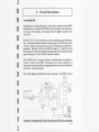
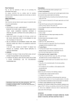
6. Circuit Description
TACHOMETER
-
Simultaneous analog and digital- speed data is required in the 4629B.
Digital format is required for RPM as data; analog for the dynamometer speed control signal. Both signals must be highly respoosive and
noise free.
PCB No. SeC.1 is the tachometer section producing speed informatiOD. The basic method consists of a clock, gated on-off by the period
of time between pulses generated by the dynamometer tachometer
generator. Because of the overall RPM range, (0 - 32000) the time
period must be selectively staged, dependant upon the immediate shaft
speed, between I, 1/10 or 1160of a shaft revolution.
Since RPM is now a reciprocal value, a math function is required to
)
convert it back to true RPM. AU functions are under command of a
microprocessor that performs ranging decisions, math and calibration
processes in microseconds.
)
The block diagram identifies the basic elements. The MPU section
-
U24
)
U25
FREQ.IlATiO
SELECT
UI7
1.16-.0 0.00::
1 w-tr
I,.G-I u.4-I~
)
~-,
]
u'"
u"
n
oU
U16
U'
U2
us
U20
--
U6
MPU
lJ7.9,IO
UI5
,
C<:IO#ITEIII
]
]
]
SPEED
"""'''
16 BIT
-
PNI5
~"
_..=00
""'"
-,~ -
""
contains a Programmable Read Only Memory (PROM) and periph6-1
L
eraJ [nterface Adaptor (PIA) for program and I/O conlt'ol. Addition~
ally, there are buffers and other "hand.shaking" elements.
The speed transducing function is complex, and only elemental mea.
surements for adequate power supply voltages and speed signal output
may be done easily. The analog speed output signal may be measured
between pin 15 and 17 on U15. This voltage is between 0 to 5.0 VDC,
full scale./oTeach speed IWlge. U a voltage proportional to speed is
present here, then it's a reasonable assumption that everything in the
speed sectiOD is working properly.
[
[
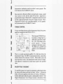
SPEED CDNTRDL
The following condensed diagram shows the speed contr01 section
located on PC Bd., TCC.!. Using the analog speed information from
~~
SPEED CONTROl
DFF. AM~.
6_
PO\IoERAAIPlFER
D-70VOC
DYN,A'
'"''''
coo.
~~~~A,=!1
,
-UIA
"
STA8UT'I'
~
II
U15, pin 15 ofSCC~l,this signal
is app tied to the invertin g inp ut
of differential operational am.
plifier. Ulb. Thenon~inverting
input is the reference input "N.
D/A," established by the main
processor from external instructions. The difference, ampli~
fled, commands the torque level
of the Dynamometer Hysteresis
[
[
[
[
[
[n series with N~D/A. is the front panel manual SPEED CONTROL.
With CW rotation, this control decreases the MPU specified value and
determines tbe value of tbe speed control input It is not shown on the
diagram, but it is essentially in series with the "N~D/A" signal.
As in any closed loop system; to maintain stability the rate of change of
dynamometer torque must never exceed the ability of the control
system to respond to it On tbe other hand, excessive rate control
results in a system so sluggish. you can go out and have lunch waiting
for things to happen. On small dynamometers, response rates are quite
different from tbose on larger dynamometers. Therefore, a magnitude
adjustment for the rate feedback signal. to suit the individual motor.
[
[
[
[
6.'
r
]
I
)
I
)
)
dynamometer combination. must be provided - and set properly. This
is the functioD of the STABILITY control.
Since current in a Hysteresis Brake is proportional to torque. a small
value resistor in series witb the brake will provide a signal that is
proportional to torque. When the D.C. component is removed, we end
up with a signal proportional to the rate of change of torque. This is
(negatively) fed hack to the controlling amplifier, by UIa; quantita.
tively determined by the STABIUTY control.
TORQUE CONTROL
Torque controlling elements and the dynamometer brake driver power
supply are contained 00 the PCB No. TCC-t.
~~
.
I
]
]
]
]
]
]
]
.".
.
"
.
-'"
""'"
.o.
-,~
"'"""
,o.
P'
14
"-"<NT
SMf'LN3
"""'"
The front panel TORQUE control adjusts a voltage input to a
differential operational amplifier - Uld. This voltage is compared
against
a vohage
analogous to the brake CWTent.
The difference is amplified and
applied to the Dynamometer
Brake.
There is a second operational amplifier Ute, which also drives the
dynamomeler brake. The MPU, byexternal instructions. controls this
elemenl from the D/A CODvcrlerMO_D/A". When either a (0) or [I)
type instructioD is active, the dynamometer brake currenl is continuously adjusled 10 maintain tbe actual torque equal to the specified
value.
SAUENT POLE "COGGING"
If a specified torque level cannot be maintained. (stalled motor) then
the system will saturate and load the brake full on. A Hysteresis
-
Brake. with CWTentapplied. in the absence of rotation, willtemporarily have salient poles when the power is subsequently removed. Your
Magtrol Dynamometer User's Manual contains a description or this
6-'
1
effect. sometimes referred to as "coggi.ng."
I/O AND MAIN DATA PROCESSING
The primary MPU and GPIB controlling electronic functions are
contained on the PC Bd., MCI.l. On this assembly, US is the Microprocessor, UI0 is the Programmable Read Only Memory containing
GP8
CClN'>ECTOR
"'
"'
XTAL
4.CWHz =>
CLOCK
IMHZ I'fH
..w'U
U5
""
I
'"
I
GI'8 NTERFACE
Gl'lACONTROU.ER
,
IVA
""
I
I
the 4629B operating system. There is a 2K non volatile RAM device
identified as Ul1. The N-D/A speed reference D/A is UU. U13 and
U14 are Peripheral InterfaccAdapters.
Ul, U2, and U3 are the GPIB
interface control elements. The balance of tbe components are buffer
and timing control devices.
There is a power supply PC Bd., PSB-2 providing +Slogicpower,:t15
Volt for the analog elements and 70 VDC . 50 Watt source of power
for the dynamometer brake.
Hysteresis brakes used on all Magtr01 Dynamometers are 28 VDe
units. However, since they operate in a current controUed mode, the
driver power supply bas a 70 VDC compliance voltage to produce a
hjgb source impedance for the brake.
If you have questions, or requiremorc detailed information. please contact
MagtroI Custcmer Serna: Dept., -l>ynamometerTcchnicallnformation.
6.'
I
I
I
I
~
.
]
I
I
I
)
I
I
)
)
)
]
]
APPENDIX A: Programming examples
MAGTROL
MOTOR TEST SOFIWARE
Magtrol offers, as an option. a comprehensive
motor lest software package available aD either 5-114 or 3-112 floppy discs. To demonstrate the capabilities of this package, a (free)
demo disc is also available. For further information, or a copy of the demo disc. contact
Magtrol Sales: (716) 668-5555.
PROGRAMMING
EXAMPLES
Most of us involved in computer programming are familiar with
BASIC. In order to show the programming techniques in as simple a
context as possible all of the following are given in Microsoft Quick
BASIC 4.5,@ using a National Instruments PC2A interface.
ITyou are using some other IEEE488 interface system; modification
of the assembly language CALL subroutines will be required.
Except for the SPEED. TORQUE CRT DISPLAY program, immediately following. the primary address used in all of the other
examples is the default factory setting of 9. If you modify the code
switch setting, you will have to correct the "dev9" operands to reflect
the change. Look for the line BDNAME$ = "dev9", and modify the
9 to whatever you selected, ie; 1 thru 15.
SPEED - TORQUE CRT DISPLAY
]
]
In the foUowing example the program will ask (or the GPIB primary
address. If you haven't changed it enter 9 and speed-torque valu~
should display 00 the CRT, updating coutinuou.s1y:
-
-
A.I
1
L
ClS:
[
lOCATE 10, 20
.
INPUT.Ent.r the primary addr.ss (1.15)...
BDNAME$
eo,
CLS
.DEV. + an$
~,
an$
[
CALlIBFIND(BDNAMES, BD%) 'Inltialln the GPIB
rdS SPACES(1S) 'Dlm.nslon th.lnput.
CAllIBRD(BD%, rdS)
.pd - VAL(MIDS(rd$, 2, 5» 'Extract N
tor - VAl(MID$(rdS, 8, S» 'Extract a
lOCATE 10, 20: PAINT .Spead _ "; .pd
LOCATE 11, 20: PAINT .Torqu. _ .; tor
LOCATE 20,50: PAINT .Any k.y .nd.....
lOOP WHilE INKEY$ _ ..
SYSTEM: END
-
[
[
[
48298 DATA FROM MEMORY
RECAll.
If a PDddS or PUddS instruction was issued, aU the data from the test
run will be retained in 46298 memory; providing that the total test time
did Dot exceed SO seconds (500 test points @ .1 Sec.). Another
PDddSlPUddS instruction will append data to that already in 46298
memory. The memory is cleared (only) wbeD an "0" command is
issued and tbe data transfer successfully completed.
In the foDowing program fragment, the variable QNdataS receives the
test data from the 46298 memory. The data format is similar to that
shown on page 2-3, ex£ept thQ/ the shaft direction character (L or R) is
elim;nated. Each individual test point block is always 12 characters long.
'Routlna to acoau 4629B Memory after a PQddS or PUdclScommand
CLS
BDNAMES
eo.$
-
. .DEVS"
.
- .0.
CHA$(13j
+ CHRS(10)
'u.lgn
the CA.lF
torque..peed
wrtS
+ eo.S'O+CR-lFcommand
to 29B.
CAllIBFIND(BDNAMES, BD%) . Inillalize the GPIB
CALlIBWRT(BD%. wrtS)"Output command:
CAllIBRD(BD%, aNdatal)'Fetch a" memory
'aNdatal
now contains all 4629B te.t dat....
aNdatal
SPACES(6S02)
'Make room for
data.
What you have is a IODSdata string structured as shoWDin the following
example. Just to fill in some numbers, let's assume a speed of 1752
RPM and 85.64 OdD. torque. A block of 3 data samples, aDywbere
in tbe striug win look like:
. . .. . . . S017S2T85.64S017SZI"SS.64S01725T85.64.. . .. .
A-'
[
[
[
[
[
[
[
I
T
]
I
I
]
)
]
]
]
]
]
]
One simple method to extract indi...;dualdata pomts, would be to aeale
a FOR~NEXT loop to ''walk through" the single variable labeled
~QNda.Ia$.wWithin the loop, assign two numerical data arrays; one for
"Speed" and one for "Torque." Since it is unlikely that all of tbe
memory was filled with data., there will be zeros output where the test
stopped. You could omit these by ma1-ing the array a!l:!l:igJImentconditional ODboth torque and speed being equal to something greater than
zero. This step is Dot included in the example.
DIMSp..d(600), Torqu8(600)
n - 1 'Inltlaliz8 array number.
FOR I
-
.
2 TO 60015 STEP 12 Step. block at . 11m.
VAL(MID$(QNdatas, 1,5»
Torqu8(n) - VAL(MID$(ONdatas, I + 6, 5))
-
Sp..d(n)
n .. n +
1
NEXT
PROGRAMING EXAMPLE FOR "." COMMAND USE.
To apply a torque value to the test motor as rapidJy as possible, the
Idddd command provides a method of directly addressing the Q-D/A
convener. The J instruction requires that the Dumerical value used
with it. be a number from 1 to 4095. 10 order to relate this to torque.
first output a "Odd.dd" command. make dd.dd equal to the value of
torque you want (2.0 is selected in the example). delay a few seconds
for the system to respond and settle. then ask for the contents of the
O.D/A converter with the "X" command. Concatenate the number
returned.. with the] command.
'Routine to ule the ~I~command.
'TORS.. Torqua valua you wilh to emulata withthai command.
CLS: eOIS .. CHRS(13) + CHRS(10) . CR-LF
wrtS .. "0" + ~2.0' + eOIS '"2.0. II arbitrary
hara.
SDNAME$.. "Dew" 'primary addre.. .. 9
CALL IBFIND(BDNAME$. BD%)
CALLIBWRT(BD%,wrtS)' loading 02.0 (2.0 unltl of torque)
.
]
SLEEP (7)
Walt 7 "condl to lettle down.
wrt$ = .X~ + eol$
'Q-D/A Data requ..t.
CALlIBWRT(BD%, wrtS),
aDAS .. SPACE$(6)
always returns 4 digiti + CR.LF
CALL IBRO(BD%, OOAl) 'CIA converter value.
]
"'"
CALlIBWRT{BD%,FASTOS)'-this
maygo~forfut
FABTO$
..
+ DDAI
'.. Idddd
Qloadng..
]
1
A-'
L
PROGRAMING EXAMPLE FOR "r
COMMAND USE.
[
To apply a value of speed to the test motor as rapidly as possible, the
Zdddd command directly addresses the N.D/A converter. The Z
instruction requires a numerical value of 1 to 4095. [norder toestablisb
this value relative to the speed you wish to apply, use the Nddddd
instruction first. After the speed has settled output a "Y" data request.
The 4 digit value returned, may then be concatenated witb "Z" for fast
speed loading.
Be sure that the speed range bas been previously establishedl
'Routine to u.. the "2" command.
CLS
80S$ = CHR$(13) + CHRS(10j . CR-lF
wrtS
"" "N" + .1750"
BDNAME$
- .CEW"
+ 801$
'prlmaryaddre.s
-
[
9
- "V"
[
SPACES(fI)
CAlL I8RD(BD%,
-
NDA$)
-Z" + NDAS
CAlL IBWRT(BD%,FASTNS) 'tlla maygoanywt'NnlorquictfNloadIng.
FASTNS
L
[
_
CALL IBFIND(BDNAME$, 80"")
CALL IBWRT(BD%, wrtS)
SLEEP (7) : wrt$
+ 80lS
CALL IBWRT{BD%. wrt$)
NDA$
.
U you have questions regarding any of the above examples, or if you
have suggestions regarding software development, please feel free to
contact Magtrol Software Engineering any time.
I
I
I
I
A.'
]
I
I
I
I
I
I
)
)
,.
APPENDIX B: Inertia Correction
I
INERTIAl EFFECT ON MOTOR TEST DATA:
A major advantage of the Magtrol Speed Controlled System, is the
abilityto obtain full (free fun to locked rotor) motor performance data
bycontinuous load application with an absorptiODdynamometer. Data
acquisition is fast, resulting in minimal motor IR losses. and loading
characteristics simulate actual end-use applications.
When a motor is accelerating or decelerating, the measured torque is
the sum of the true motor torque:!: the inertial torque (stored energy)
of the system. Unless inertial torque is excluded. motor performance
data will be in error; since the measured torque will vary in proportion
to the rate of acceleranoo/deceleration.
This type of an error can produce startling test results. For example;
during rapid deceleration,
system inertia can produce apparent
efficiency greater than 1.0! This may occur as output power is divided
by input power without extracting the stored energy in the system.
Alluding to perpetual motion causes most technically oriented people
to suspicion the data.
-
DATA TIMING FACTOR
)
Since "inertial effect" is ooly a factor as speed is changing
_
and inertial
torque is proportional to rate of change. inertial value may be ex-
I
I
)
)
]
pressed as a unit of torque per change in RPM
- ;11a given
period of
ti=.
The 4629B accumulates and outputs test data at fixed intervals of 0.10
second. Therefore, change in RPM is always over that fixed period,
regardless ottesting rates. [t might seem desirable if data were output
at fixed intervals of speed or torque, like every 100 RPM's, or something nice to work with. But that would preclude the ability to extract
inertial error effects. unless we could somehow accurately measure _
and rapidly output - the clapsed timc betwecn every data point! Uyou
must have speed/torque data in even decades, there are various
B-1
L
computer software routines for (ast and accurate curve fitting tecbniques to do this (or you.
PROCEDURE
.
,
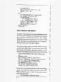
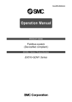
In order to create a torque Correction Factor (CF), we need:
1. A torque value equal to the inertial torque.
2. The difference in RPM (per.1 sec.) tbal crealed that value.
In the (oUowinggrapb example we have arbitrarily selected a data point
on the performance curve. What we want to do is program down by
DtCELEI'I"'llONTO!'IOlE
DYNAMIC
VSSPEEOC\.Rve~
FR
TORQUE VALUE
.780FFR_
I
w
'"
)
STATIC
TORQUE VALUE
AveRAGET~EC~ANGE
IN SPEEO BETWEEN
TI-f:SE POINTS
~DIFFERENCE
N TOROue
CF=
DIFFERENCE IN TOROLE
CHANGE
N SPEED
o
TORQUE
_
increasing torque load. and fetch a group o( test points. We have
selected the farst data point where the speed will be just less than 78%
of the Free Run speed. Call this the dynamic speed value. Additionally,
save one test point before this value, and one after. Immediately
program the 46298 (Nddddd) to a speed exactly equal to this "dynamic" value. When the speed has stabilized, fetch this as the static
torque value.
To calculate CF, first average tbe speed change between 3 test points.
Next, calculate the difference in torque between the static speed value
and the dynamic speed value. Divide this torque difference by the
average change
B-2
in speed
- and
that's all there is to it.....
[
]'0
I
I
I
)
o The test point
selection 0(".78," is fairly typical for an induction
motor. In any event, select this value in an area where the performance
curve is fairly linear, and there is a substantial torque change with
speed.
o The data must be acquired
rapidly, so that motor heatiftg does not
degrade performance adding a false difference between the static and
dynamic torque values.
o The input line voltage must be stable for 1 or 2 seconds that this lest
)
requires. Torque varies by tbesquilll' of the change in line voltage: use
a regulated power source.
]
INERTIA CANCELlATION
]
]
]
]
PROGRAM
The following nine steps outline a computer program, in Quick Basic,
to conb'ol the 46298 for the acquisition of a "CF' value.
Initialization:
'fr .. fr.. run apeed. You must ".Ign Ihl. ...el.,.,
BDNAME$ .. ~DEV9"'Primary addr .. default cOd. 9.
CAlL IBFlND(BDNAME$.80%)' Inltlallz8tM GPIB
808$.. CHRS(13)+CHR$(10)
'CR-LFtermlnallon char'..
Programming steps:
1. With the system up and fllnning, command a PD70 instruction to
Program Down to 78% of the free ramspeed:
wrt$ .. "PD70' + eOa$
'Program Downat a la.t rate.
.Assign room lor the data
CAlL I8WRT(BDNAMES, wrtS) 'Send it to the 4629B.
]
]
]
]
rdS
- SPACES(15)
2. Collect data in an array, (Single data point
+ CR-LF
= SdddddTddd.dL,)
x - 0 'X I. our array # - ..Iected .peed point.
DO:X-X+1
CAU.IBRD(BD%.rd$) 'rdS ,. U. data from 29B.
NC(X) - VAL(MtD$(rdS,
2, 15)) 'SPEED
aDIX)
VAL(MID${'d$.8. 51)
~OAQUE
.
LOOP UNTILND(X) <.18
-'r
'Ir
_ Iree run RPM 88Slgned.
D.'
MAGTROL LIMITED WARRANTY
Magtrol products are warranted
against defects in materials and workmanship for a period of ninety (90)
days from the date of delivery. We will
repair or replace products which
prove to be defective during the warranty period provided they are
returned to Magtrol. Additionally, any
repairs which may become necessary
beyond the ninety (90) day warranty
period will be made subject to review
by our quality control department. No
other warranty is expressed
or
implied. We are not liable for consequential damages.
MagtroJ
Inc. Buffalo, New York