1
MAGTROL
Model 5240
Programmable
Dynamometer Controller
User s Manual
MAGTROL
MAGTROL,, INC.
Sales and TTechnical
echnical Assistance
70 Gardenville Parkway
Buffalo, New York 14224
In New York - (716) 668-5555
Outside N.Y. - (800) 828-7844
Fax - (716) 668-8705
www.magtrol.com
Manufacturers of:
Motor Test Equipment
M
Hysteresis Brakes and Clutches
While every precaution has been exercised in
the compilation of this document, Magtrol,
Inc., assumes no responsibility for errors or
omissions. Additionally, no liability is assumed for any damages that may result from
the use of the information contained within
this publication.
IBM® is a registered trademark of International Business Machines Corporation.
Quick Basic® is a registered trademark of
Microsoft Corporation.
Microsoft® is a registered trademark of
Microsoft Corporation.
74M121 01/00 25
Table of Contents
SALES AND TECHNICAL ASSISTANCE ........................................................................................ ii
1 - INTRODUCTION ...........................................................................................................................1
LINE VOLTAGE .................................................................................................................................... 1
INITIAL CHECKOUT ............................................................................................................................ 1
OPERTIONAL/EQUIPMENT CHECK ................................................................................................... 2
MODEL 5240 CAPABILITIES ............................................................................................................... 3
2 - INSTALLATION.............................................................................................................................4
GPIB-COMPUTER INSTALLATION ..................................................................................................... 4
SOFTWARE INSTALLATION ............................................................................................................... 4
PRIMARY ADDRESS ........................................................................................................................... 5
DATA ACQUISITION ............................................................................................................................ 5
DATA ACQUISITION PROBLEMS ....................................................................................................... 6
3 - INSTRUCTION SET ......................................................................................................................7
DYNAMOMETER CONTROL MODES ................................................................................................. 7
SPEED CONTROL RANGING ............................................................................................................. 7
MODEL 5240 INSTRUCTION SET ....................................................................................................... 8
FRONT PANEL CONTROL FUNCTIONS .......................................................................................... 12
Torque .................................................................................................................................................... 12
Speed ...................................................................................................................................................... 12
Current Gain .......................................................................................................................................... 12
Proportional Gain ................................................................................................................................. 12
4 - CONTROLS, LEDS AND I/O ......................................................................................................12
Error ...................................................................................................................................................... 13
Stability .................................................................................................................................................. 13
FRONT PANEL INDICATORS (LEDS) ............................................................................................... 13
Dyno Brake ............................................................................................................................................ 13
GPIB Error ............................................................................................................................................ 13
GPIB Transfer ....................................................................................................................................... 13
Speed Sync ............................................................................................................................................. 13
Auto Speed Range .................................................................................................................................. 14
GPIB Torque .......................................................................................................................................... 14
GPIB Speed ............................................................................................................................................ 14
CTLS Active ........................................................................................................................................... 14
MODEL 5240 ELECTRICAL I/O ......................................................................................................... 14
GPIB Interface ....................................................................................................................................... 14
DYNAMOMETER BRAKE .................................................................................................................. 15
ACCESSORY TORQUE-SPEED OUTPUT ........................................................................................ 15
ACCESSORY CABLE ........................................................................................................................ 16
DYNAMOMETER ............................................................................................................................... 16
OPERATING INSTRUCTIONS ........................................................................................................... 17
Manual Torque Control ......................................................................................................................... 17
GPIB Torque Control (Computer Control) ........................................................................................... 18
Manual Control ..................................................................................................................................... 18
GPIB Speed Control (Computer Control) ............................................................................................. 19
5 - CALIBRATION ............................................................................................................................21
BEFORE PROCEEDING .................................................................................................................... 21
TRIMPOT FUNCTION ........................................................................................................................ 22
TORQUE ZERO (NULL) ADJUSTMENT ............................................................................................ 22
FULL SCALE TORQUE CALIBRATION ............................................................................................. 22
ACCESSORY TORQUE OUTPUT CALIBRATION ............................................................................ 23
MANUAL TORQUE CONTROL ZERO ............................................................................................... 23
GPIB "Q" COMMAND TORQUE NULL ............................................................................................... 23
MODEL 5240 SPECIFICATIONS ....................................................................................................... 24
Speed Control ........................................................................................................................................ 24
Torque Control ...................................................................................................................................... 24
A WORD ON SPEED VARIATIONS ................................................................................................... 24
6 - CIRCUIT DESCRIPTION .............................................................................................................25
TACHOMETER .................................................................................................................................. 25
SPEED CONTROL ............................................................................................................................. 26
GPIB Speed Control .............................................................................................................................. 26
MANUAL SPEED CONTROL ............................................................................................................. 27
TORQUE CONTROL .......................................................................................................................... 27
GPIB Torque Control ............................................................................................................................ 27
MANUAL TORQUE CONTROL .......................................................................................................... 27
SALIENT POLE "COGGING" ............................................................................................................. 28
I/O AND MAIN DATA PROCESSING ................................................................................................. 28
APPENDIX A: PROGRAMMING EXAMPLES ................................................................................29
SPEED-TORQUE CRT DISPLAY ....................................................................................................... 29
RECALL MODEL 5240 DATA FROM MEMORY ................................................................................ 30
PROGRAMMING EXAMPLE FOR “I” COMMAND USE ..................................................................... 30
PROGRAMMING EXAMPLE FOR “Z” COMMAND USE .................................................................... 31
APPENDIX B: INERTIA CORRECTION .........................................................................................32
INERTIAL EFFECT ON MOTOR TEST DATA ................................................................................... 32
DATA TIMING FACTOR ..................................................................................................................... 32
PROCEDURE ..................................................................................................................................... 32
INERTIA CANCELLATION PROGRAM .............................................................................................. 33
Programming steps ................................................................................................................................ 34
CORRECTING TEST RUN PERFORMANCE DATA .......................................................................... 35
APPENDIX C: DRAWINGS .............................................................................................................36
78B155 ............................................................................................................................................... 36
78B156 ............................................................................................................................................... 37
78B157 ............................................................................................................................................... 38
78B159 ............................................................................................................................................... 39
MAGTROL LIMITED WARRANTY ..................................................................................................40
While every precaution has been exercised in the compilation of this document, Magtrol Incorporated
assumes no responsibility for errors or omissions. Additionally, no liability is assumed for any damages
that may result from the use of the information contained in this publication.
1 - Introduction
Your Model 5240 has been adequately packaged for shipping. Please save all shipping cartons and packaging
material until the unit has been thoroughly checked. If there is evidence of shipping damage, notify your carrier
and Magtrol Customer Service as soon as possible.
Be sure to check the carton and packaging material carefully for cord sets and other hardware.
LINE VOLTAGE
WARNING!
Please check the line voltage setting before operation!
Model 5240 will operate from either a 120V/60Hz or 240V/50Hz power source, but the unit must be set for the
appropriate point-of-destination line power. This adjustment is made using a switch within the line cord receptacle on the rear panel.
The line cord is a detachable NEMA Standard 3 wire. All Magtrol Dynamometers and Electronic Products
require that cabinets and fixtures be earth grounded for proper equipment operation and to ensure safety of
operating personnel.
INITIAL CHECKOUT
NOTE: Throughout this manual, the following terms are used:
•
LED refers to the Light Emitting Diode indicators on the front panel of Model 5240.
•
The term GPIB (General Purpose Interface Bus) is interchangeable with IEEE-488.
•
“Q” refers to Torque.
•
“N” refers to Speed.
•
CW means Clockwise
•
CCW means Counterclockwise
In order to perform the following operational check, you must have a Magtrol Dynamometer with a test motor
installed. No computer interface or digital torque-speed readout equipment is necessary. Two cables are required to connect Model 5240 to the dynamometer:
•
•
14 pin Instrumentation Ribbon Connector Cable.
2 pin Dynamometer Brake Power Cable.
Your Dynamometer User’s Manual, Chapter 1, shows how these cables are connected.
Magtrol 5240: Introduction
1
OPERTIONAL/EQUIPMENT CHECK
1.
Set the Dynamometer BRAKE switch (left side) ON.
Set the TORQUE potentiometer fully CCW (zero load torque).
Set the SPEED potentiometer fully CW (max. range).
Set the GAIN, ERROR and STABILITY controls to approximately the 9 o’clock position.
2.
Turn ON the Model 5240 POWER switch. The green CTLS ACTIVE LED should illuminate. Model
5240 is now in the manual TORQUE control mode. NOTE: At power on, Model 5240 defaults to the
manual TORQUE control mode.
3.
Start the test motor and allow the motor speed to stabilize for a few seconds at its no load speed.
4.
Slowly rotate the TORQUE control knob clockwise (CW - in direction of arrow). NOTE: The arrow
direction indicates that the applied torque increases in the CW direction.
The DYNO BRAKE LED will illuminate as brake power is applied, causing load torque to be applied
to the motor. The applied torque increases as the knob is rotated CW. For most motors, torque
loading will be observed by a reduction of motor speed as torque is applied. Be careful not to overload or stall the motor, as prolonged overload can cause the motor to overheat.
5.
Return the TORQUE control to the fully CCW position. The DYNO BRAKE LED should go out as
the motor load torque returns to zero.
6.
Switch the BRAKE ON/OFF rocker switch OFF and then ON. The AUTO RANGE LED will illuminate, indicating that the Model 5240 is now in the manual speed control mode. The CTLS ACTIVE
and AUTO RANGE LEDs should be illuminated.
7.
Slowly rotate the SPEED control knob counterclockwise (CCW - opposite the arrow direction). The
arrow direction indicates that motor speed control increases with CW rotation and decreases with
CCW rotation. The DYNO BRAKE LED should illuminate, and the motor should slow down under
speed control.
NOTE: If the motor is unstable, adjust the STABILITY control CW as necessary to restore
stability. Be careful not to overload or stall the motor, as prolonged overload can cause the motor to
overheat.
Return the SPEED control knob fully CW.
8.
Remove power to the motor under test.
This completes the Model 5240 manual mode operational checks. For GPIB PC computer control mode use,
please refer to section 2 - GPIB COMPUTER INSTALLATION.
2
Magtrol 5240: Introduction
MODEL 5240 CAPABILITIES
The Model 5240 is a speed controlled power supply, designed to interface with any type of IBM compatible
computer using an IEEE-488 instrument controller. Model 5240 may be used to control any Magtrol Load Cell
Dynamometer. In addition, it may be set to return current Torque-Speed data to the computer. The unit may be
used without a computer, but will function at only a fraction of its capability and will require a Magtrol digital
readout device to display torque and speed.
In a computer controlled environment, the following motor testing capabilities are available:
•
Proportional (P), plus Integral (I), plus Derivative (D) closed loop speed control - PID loop. Control
parameters are adjustable by the front panel controls of proportional GAIN (P), ERROR (I) and STABILITY (D).
•
Torque (Q) vs. Speed (N) data acquisition, at a rate of 10 readings per second.
•
Automatic Q-N continuous (progressive) loading in either decreasing or increasing speed mode.
•
Capability to remove the Effects of Inertia from dynamically-obtained data. See Appendix B.
•
Q or N programmable test points.
•
Data storage (nonvolatile) within the unit, up to 500 Q-N test points.
•
Complete curve capability for most types of motors, including single/poly phase induction, AC/DC
series, PMDC, brushless DC, air and internal combustion (if suitably coupled).
NOTE: In speed mode, closed loop control between locked rotor and 60 RPM may be erratic, depending on
the test motor. Programmed loading in the speed mode may therefore not be possible for very low speed gearhead and stepper motors.
Magtrol 5240: Introduction
3
2 - Installation
Please be sure that the computer and Model 5240 are both turned OFF when you install the GPIB connector
cable.
If you have completed the equipment checkout as outlined in Chapter 1, the Model 5240-Dynamometer interconnection is complete. If an optional Magtrol Digital Readout is to be interfaced with the unit, you will need a
Magtrol 7 pin DIN to 14 pin Ribbon Connector Cable. This cable assembly is Magtrol PN 88CS09 and is in
stock at the factory. If a readout was supplied with Model 5240, the cable will be included. Please refer to Page
1-2 of your Dynamometer User’s Manual for instructions on connecting the readout.
Although numerous computer interfacing methods exist, all Magtrol electronic instruments use the IEEE-488
(GPIB) Standard for the following reasons:
•
GPIB parallel communication is inherently faster than serial interfaces.
•
In motor testing, at least five separate parameters must be synchronized. A system of easy, fast access to
more than one instrument is essential. With the GPIB, up to 15 instruments may be accessed on one port.
•
The GPIB has rigid data formatting and hardware standards. This increases the chances that all functions
will work properly when the hardware/software is installed.
GPIB-COMPUTER INSTALLATION
The GPIB interface is not a standard item on most computers. An interface card must be installed, and the driver
software made resident on disk. Several manufacturers provide these products, and some systems exchange data
more rapidly than others. In motor testing, the test rate and speed of data acquisition is very important. We
recommend using National Instruments Corporation’s PN GPIB-PC2A for IBM® compatible PCs. Additionally, you will need to install an IEEE-488 Cable between the computer and Model 5240.
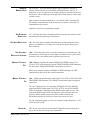
SOFTWARE INSTALLATION
A number of formatting questions must be answered during GPIB software installation. The following items
pertain to Model 5240:
All GPIB data acquisition systems require the use of data termination
characters. Model 5240 uses the Hewlett Packard HPIB standard termination
characters “Carriage Return (CR)-Line Feed (LF)” (in that order), and looks
for these symbols to terminate communication.
Codes for CR - LF
BASIC HEX DEC
CR = CHR$(13) ØD 13
LF = CHR$(1Ø) ØA 1Ø
You may be asked to set a communication fault delay timeout, to alleviate a computer hang-up. Do not set this
period too short. Leave at least one second. If the computer resets the interface prematurely, the host instrument
may hang up, waiting to find the never-to-happen “CR-LF.”
4
Magtrol 5240: Installation
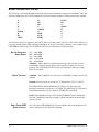
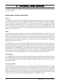
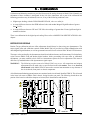
PRIMARY ADDRESS
CODE SWITCH
Segment #
All instruments serviced on the GPIB have a separate primary address code. On the rear
panel, next to the GPIB connector, there is an opening which provides access to the code
selection switch. The default setting (from the factory) on Model 5240 is nine (09). If you
wish to change the code, this chart will help you obtain the setting you want. Please note that
the MSB is to the right. Switch segment identification resulted in the binary code notation
being reversed from the standard convention, where the LSB is normally on the right.
Some PC interfaces will access 1 to 15 (4 Bit) primary 1 1 2 3 4 5
address numbers only. Others may access up to 31 (5 Bit)
codes, even though the GPIB capability is limited to 15 ∅
instruments. The Model 5240 Primary Address uses the 5
bit format. Before selecting a value greater than 15, however, check with your particular interface’s primary address code range capability.
6
7
Not used
8
1 2 3 4 5
Code
0 0 0 0 0
0
1 0 0 0 0
1
0 1 0 0 0
2
1 1 0 0 0
3
0 0 1 0 0
4
1 0 1 0 0
5
0 1 1 0 0
6
1 1 1 0 0
7
0 0 0 1 0
8
1 0 0 1 0
9
0 1 0 1 0
10
1 1 0 1 0
11
0 0 1 1 0
12
1 0 1 1 0
13
0 1 1 1 0
14
1 1 1 1 0
15
0 0 0 0 1
16
DATA ACQUISITION
When the systems are interconnected, the first thing you might want to verify is that Model 5240 and the host
computer are communicating.
Model 5240 requires no specific input instruction in order to output immediate torque and speed data. Simply
follow your computer/GPIB interface instructions and issue a data input or read command. If our primary
address is set and addressed correctly, Model 5240 will respond. It will probably be necessary to set your input
variable to 15, i.e. 13 characters plus CR-LF.
Speed-Torque data is a fixed length string, ASCII format, floating point decimal, structured as follows:
SdddddTdddd.L
Where d = decimal digit, 0 through 9, “S” indicates that the following 5 digits are RPM, and “T” indicates that
the next 4 digits + decimal point is Torque. The last character (shown as “L”) may be either “L” or “R.” “L” =
CCW dynamometer torque application, “R” = CW.
The decimal point location will depend on the specific dynamometer and torque range in use. The CR-LF are
symbolic and will not display.
For example: Suppose a motor is running at 1725 RPM clockwise, with the dynamometer loading the motor to
22.6 oz.in. Model 5240 will transmit:
S01725T022.6R
or
S01725T22.60R
By string manipulation, the speed-torque and shaft direction (if required) may be extracted and assigned separate numerical variables for data processing. No decimal point is used in the speed value. The torque always
contains a decimal point.
Magtrol 5240: Installation
5
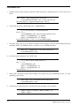
The following is a simple - single input instruction - source program written in Microsoft Quick Basic® using a
National Instruments Corporation GPIB-PCIIA, P.N. 320043-01 IEEE-488 Interface. It will access Model 5240,
retrieve immediate data and display it exactly as received.
'$INCLUDE: 'c:\gpib-pc\qbasic\qbdecl.bas'
CLS
N$ = “DEV9” ‘ Assign the primary address, (assume) 09.
rd$ = SPACE$(15) ‘Make room for the data.
CALL IBFIND(N$,BD%) ‘Subrtn Call - Init. Pri Addr.
CALL IBRD(BD%,rd$) ‘Subtrn Call, Input data to rd$
PRINTrd$ ‘Place it on the CRT
END
If the communication checkout is functioning properly, skip the following.
DATA ACQUISITION PROBLEMS
Data acquisition problems are typically frustrating, but not difficult. The following may provide a clue to some
possible causes.
•
Whenever communication is complete - and properly terminated - the GPIB TRANSFER LED will be
OFF.
•
The GPIB ERROR LED simply indicates that an instruction character was not understood, i.e. does not
match the unit’s programmed set. The LED extinguishes upon acceptance of any subsequent character(s).
•
If the GPIB TRANSFER LED remains ON, this indicates that communication has occurred, but the
computer either has not accepted the data (probably the CR-LF) or has not released the bus for some
reason. Check your interface installation software instructions. Model 5240 will probably be “hung up.”
You must turn the main power switch OFF (left side), wait a few seconds, then ON again to reestablish
operation. The only time that the GPIB TRANSFER LED will remain ON - in proper operation - is when
your program contains a continuous loop, and communication runs uninterrupted.
•
If the GPIB TRANSFER LED is off, repeat the data acquisition instruction, but keep an eye on the LED
to see if it flashes. If it does not flash, look for a primary address or interface hardware problem. If it
flashes ON, then OFF, you are very close. Recheck your program, especially how you handle the input
variable.
You may save time by contacting Magtrol Customer Service. Ask for “GPIB software assistance.”
6
Magtrol 5240: Installation
3 - Instruction Set
Before proceeding with the instruction set, some fundamental operating principles should be covered.
DYNAMOMETER CONTROL MODES
Dynamometer torque load is applied to a test motor by either of two modes of operation:
1.
Direct torque control, where regulated and fixed current is applied to the Dynamometer Hysteresis
Brake.
2.
Speed control, where the immediate value of speed is compared to a reference, and brake current is
proportioned to the difference.
In the speed mode (2), the Dynamometer/Model 5240 becomes a closed loop system, forcing the test motor to
operate at a fixed speed. Two digital-to-analog converters form an integral part of this function, controlled by
the system microprocessor. For reference within this manual, these elements are identified as Q-D/A for torque
and N-D/A for the speed digital-to-analog control elements.
SPEED CONTROL RANGING
Because of the wide range of motor operating speeds accommodated, it is necessary to program Model 5240
with the test motor’s maximum RPM to establish the speed range value. There are two methods to accomplish
this:
1.
Non-instructed: If the following three conditions are met, the unit will establish the correct RPM
operating range automatically.
•
•
•
No previous GPIB SPEED range instruction.
BRAKE switch OFF.
Test motor installed - and running - with the dynamometer shaft speed above 256 RPM.
Model 5240 will assume the current RPM value to be the free-run motor speed, and will select and
retain the correct speed range. The acceptance will be signaled by the illumination of the AUTO
RANGE LED.
2.
GPIB Specified: This method of range control has precedence, and the instruction suspends the
AUTO RANGE function described above. To recover the AUTO RANGE capability, refer to the “R”
or an “N” instruction. “Set An Operating Speed Range” is described below.
Magtrol 5240: Instruction Set
7
MODEL 5240 INSTRUCTION SET
The following is a condensed alphabetical listing of the control characters recognized by the Model 5240. The
characters dddd represent a variable numerical value following the identifier. Leading zeros are not required.
A
B
C
D
E
Fddddd
H
HS
Idddd
M
M1
M0
N
Nddddd
O
PDdd
PUdd
PDddS
PUddS
PR
Q
Qdddd
R
S
X
Y
Z
All characters must be in uppercase and ASCII format. All entries must end with a CR-LF (Hex 0D-0A), as
previously outlined in the GPIB-Computer Installation, Section 2. If a string or character is not recognized, the
GPIB ERROR LED will go ON. The ERROR LED will reset OFF upon a valid instruction.
SET AN OPERATING
SPEED RANGE
SPEED TESTPOINT
“A” = 2,000 RPM
“B” = 4,000 RPM
“C” = 8,000 RPM
“D” = 16,000 RPM
“E” = 32,000 RPM
“Fddddd” Where ddddd is a specified speed range value between 256 and
32,000 RPM, which the motor speed is not to exceed. Leading zeros are not
required. The AUTO RANGE LED will go OFF when any of the above range
values are accepted.
“Nddddd” Where ddddd is any value up to 32,000 RPM. Leading zeros are not
required.
Example: Force the motor to operate at 1787 RPM. Enter "N1787" (CR-LF).
The GPIB SPEED LED and SPEED SYNC LED go ON. The motor will
decelerate (with some overshoot) to 1787 RPM. The SPEED SYNC LED may be
somewhat intermittent, refer to Chapter 4, STABILITY CONTROL.
NOTE: If the BRAKE switch is OFF, the DYNO BRAKE LED will flash ONOFF-ON, signaling the inability to comply with the instruction, until the brake
switch is set ON.
RESET FROM GPIB
SPEED CONTROL
8
“N” (only) Sets GPIB SPEED LED off, resets Model 5240 to the highest speed
range, enabling the AUTO RANGE capability.
Magtrol 5240: Instruction Set
TORQUE TESTPOINT
In the following, the actual torque values selected (dddd) must be within the
capability of the dynamometer in use. This value (full scale rating) is shown on
the dynamometer front panel.
“Qdd.dd” Where the torque value in any units = dd.dd. Floating point notation,
leading zeros are not required (i.e. d.ddd, dd.dd, ddd.d or dddd).
The GPIB TORQUE LED will go ON. The motor will be loaded to the value
specified.
Example: For “Q32.5”, load the motor with 32.5 of whatever torque unit is
applicable, as specified on the dynamometer front panel, i.e. OZ.IN., GM.CM,
mNm, etc. If the BRAKE switch is off, the DYNO BRAKE LED will flash ONOFF-ON until the switch is closed.
RESET TO
ZERO TORQUE
“Q” (only) Removes the torque load from the motor. The GPIB TORQUE LED
will go OFF.
APPLY FIXED
BRAKE POWER
“Idddd” Numerical value (dddd), to be any whole number between 1 and 4095,
is converted to 12 bit binary and applied directly to the Q-D/A converter. Do not
use a decimal point. This results in a fixed application of voltage (and torque) on
the dynamometer brake. The value (dddd) translates to 0 to 28 V.D.C. The GPIB
TORQUE LED will go ON.
This instruction is a very fast method to load a motor to a specified value of
torque. The value (dddd), however, must be predetermined. There will be longterm torque drift (subject to effects of hysteresis brake heating) since the
function is open-loop. A method to establish an Idddd to Torque Calibration is
shown in the programming examples of Appendix A.
PROVIDE THE
IMMEDIATE Q-D/A
VALUE
“X” This entry instructs Model 5240 that upon the next computer-read/Model
5240 write function, instead of current speed-torque data, the contents of the QD/A converter should be returned. The number returned will be the decimal
equivalent of the binary 12 bit Q-D/A word. This information is useful when
establishing a correct Idddd instruction. After the single data write instruction,
the unit automatically resets to provide standard speed-torque data on
subsequent write (data output) instructions. See Appendix A for further
information.
APPLY FIXED SPEED
“Zdddd” dddd is converted to a 12 bit binary value and applied directly to the
speed N-D/A converter. The value of dddd must be from 0 to 4095.
For this instruction to work properly, the speed range A through F must have
been previously output.
This instruction is a very fast method to load a motor to a specified value of
speed. The value (dddd), however, must be predetermined. A method to establish
an “Zdddd” to speed value is shown in the programming examples of Appendix
A.
Magtrol 5240: Instruction Set
9
PROVIDE
CURRENT
N-D/A VALUE
“Y” This entry instructs Model 5240 that upon the next computer-read/Model
5240 write function, instead of current speed-torque data, the contents of the ND/A converter should be returned. This information is useful when establishing a
correct “Zdddd” instruction. After the single data write instruction, the unit
automatically resets to provide standard speed-torque data on subsequent write
(data output) instructions. See Appendix A for further information.
PROGRAMMED
LOAD TESTING
“PDdd” Program Down (speed mode) from free-run to locked rotor at a rate
proportional to dd. Where: dd is any number from 1 to 99, relating indirectly to
RPM per second, where 1 is the slowest and 99 the fastest. The SPEED SYNC
LED goes ON if the instruction is accepted.
THE
The absolute rate of speed decrease, or test time, is dependent upon the free run
speed of the test motor and the speed range setting. Therefore, the rate specified
by “dd” must be established by test. Try 20 to start, then adjust up or down from
there.
If the speed range information was not established prior to the instruction, the
GPIB ERROR LED will go ON, indicating failure of the instruction to execute.
To correct this, command an “A through F” instruction. Please note: As a rule,
either the AUTO RANGE LED or the GPIB SPEED LED must be ON,
indicating that a speed control range has been specified, in order for a “PDdd”
instruction to execute.
“PUdd” Program Up at a rate of dd, same as “PDdd” except that the RPM is
increasing. To be accepted, this instruction must have been preceded by an N or
PD instruction.
“PDddS” or “PUddS” Same as “PDdd-PUdd” above, except that up to 500
blocks of speed-torque data are stored within Model 5240’s memory for future
retrieval. This releases the host computer for other processing as a test is taking
place.
In order not to overrun the memory, the total test time must be maintained under
45 seconds. As long as the memory is not overrun, multiple PD(S)/PU(S)
instructions will accumulate. See “O” command and Appendix A for further
information.
CANCEL PD/PU
ROUTINE
10
“PR” Resets to free run speed from a PD/PU instruction, providing the shaft is
still rotating. The current speed range status is retained. If there was a previous
“Nddddd” instruction, the unit will return to that. Please note that the PR
instruction will fail, resulting in a locked rotor condition, if the shaft speed is
below 100 RPM when the instruction is issued.
Magtrol 5240: Instruction Set
RETRIEVE
MEMORY DATA
“O” (not zero) This entry instructs Model 5240 to output the contents of
memory obtained from a previous PDddS or PUddS function. After an “O”
instruction is received, upon the next computer read cycle, instead of current QN data, there will be 6000 bytes of data plus CR-LF from memory. Set the input
variable to 6002.
Data in memory is retained indefinitely, even if Model 5240 is switched OFF.
The memory is automatically retained, and only erased after a successful “O”
command has been executed.
Appendix A provides a programming example.
SET STANDARD
RESOLUTION
SET HIGH RESOLUTION
“S” All torque data will be formatted and fixed to exactly the resolution of the
dynamometer front panel torque identification.
“H” Fixes the torque resolution from that shown on the dynamometer front
panel, by an additional 1/2 LS digit (0-2-4-6-8) but not greater than 1 part in
9999 resolution.
SET AUTOMATIC
RESOLUTION CONTROL
“HS” Allows the torque value to increase resolution by 10 automatically. The
decimal point will shift right or left one digit to maintain at least 1 part in 2000
resolution. This is the default mode of operation (at power up).
MANUAL CONTROLS
OFF
“M0” (M zero) Disables the manual TORQUE and SPEED controls. The
CTLS ACTIVE LED extinguishes, and the GPIB TRANSFER LED illuminates.
The front panel TORQUE and SPEED control knobs are inactive.
When using computer controlled TORQUE or SPEED functions, the “M0”
instruction must precede all other control instructions.
MANUAL CONTROLS
ON
“M1” Enables the manual torque control mode. The CTLS ACTIVE and GPIB
TRANSFER LEDs illuminate. The TORQUE control knob adjusts the applied
torque load.
The “M1” followed by the “N” instruction (TORQUE and AUTO RANGE)
enables the SPEED control mode. The CTLS ACTIVE and AUTO RANGE
LEDs will illuminate, indicating that the SPEED control mode is active. The
front panel SPEED control knob will control the speed of the test motor by
applying variable loading torque to the motor (within controller and
dynamometer ratings) as necessary to control speed at the set value.
The “M” instruction toggles (reverses) all front panel control functions, i.e. ON
to OFF and OFF to ON.
RESET ALL
Magtrol 5240: Instruction Set
“R” Restores the controller to the manual TORQUE control mode (mode at
power turn on) and clears all previous instructions.
11
4 - Controls
Controls,, LEDS and I/O
This chapter describes the front panel control functions and indicators, rear panel Input/Output connections and
controller operation.
FRONT PANEL CONTROL FUNCTIONS
TORQUE
The TORQUE control knob applies an adjustable current through the dynamometer brake coil, causing load
torque application to the test motor. The TORQUE control knob is a 10-turn adjustment, capable of applying up
to 0.75 amps of DC current through the brake coil. The front panel arrow indicates the direction of rotation
needed to apply increasing brake torque, i.e. CW to increase and CCW to decrease torque application. A half
turn or so of rotation may be needed before the brake starts to respond. The amount of TORQUE knob rotation
necessary to obtain maximum dynamometer torque will depend on the dynamometer model used. Torque control
mode is active at power turn on.
SPEED
The SPEED control provides an adjustable speed set point to which the PID (Proportional + Integral + Derivative)
control loop modulates the brake current. This results in dynamic application of brake torque to maintain the
motor speed at set point. The front panel arrow indicates the direction to increase (CW) or decrease (CCW)
speed. Speed control permits the test motor to be controlled through most unstable regions of the motor’s
characteristic torque curve. Speed control mode is activated from the torque control mode, by switching the
BRAKE ON/OFF switch off, then on.
The SPEED control is a 10-turn adjustment, ranging from near zero speed at the fully CCW position to the
control range maximum at the fully CW setting. In speed control, the free run motor speed must be programmed
into Model 5240’s memory to establish the controller control range. At controller power turn on, the control
range defaults to the 32,000 RPM range. This establishes the speed control set points at 32,000 RPM when the
speed control knob is set fully CW and near zero at the fully CCW position. If, for example, you are testing a
motor with a free run speed of 16,000 RPM, and you use the default range of 32,000 RPM, the SPEED control
knob would have to be rotated approximately five turns CW before the speed control is established.
CURRENT GAIN
The CURRENT GAIN control is the outer adjustment knob of the concentric dual gain control cluster. This oneturn control adjusts the gain of the current output amplifier to provide rated torque loading from the dynamometer.
Refer to the OPERATING INSTRUCTIONS - MANUAL TORQUE CONTROL section on page 17 for the
adjustment procedure.
PROPORTIONAL GAIN
The PROPORTIONAL GAIN control is the center knob of the concentric dual gain control cluster. This GAIN
control is the voltage gain of the proportional factor (P) of the PID speed control loop. This control is functional
only in the speed control mode. The control is a one-turn adjustment of gain of the speed error signal (the
difference between the set and the actual motor speed). To ensure best speed control response, the GAIN control
should be adjusted for as high a gain setting as possible, while maintaining stable (non-oscillatory) motor
control. The control is set in conjunction with the ERROR and the STABILITY controls.
12
Magtrol 5240: Controls, LEDs and I/O
ERROR
The ERROR control is the integral of speed error and is functional only in speed control mode. The control is a
one-turn adjustment of integral gain. Increasing the integral holds the actual motor speed closer to the set point
value. This control is set in conjunction with the GAIN and STABILITY control settings.
STABILITY
The STABILITY control is the negative rate feedback of brake current. Brake current is sampled by picking off
a portion of the voltage drop across a 0.5 ohm current sampling resistor in series with the brake coil. Since brake
torque output is proportional to current flow through the brake coil, this sampled voltage represents the applied
brake torque. This torque signal is differentiated to provide a signal proportional to the torque rate of change.
This negative rate signal (derivative) is algebraically summed with the PROPORTIONAL and INTEGRAL
signals to provide response stabilization of motor speed. This rate feedback signal acts to improve and stabilize
the test motor’s response. Like the GAIN and ERROR controls, it is a one-turn adjustment, providing greater
control stability, and is functional only in the speed control mode.
FRONT PANEL INDICATORS (LEDS)
The following is a detailed explanation of the front panel LED functions.
DYNO BRAKE
This is a red LED indicator which goes ON anytime the dynamometer has - or is calling for - torque, regardless
of the BRAKE switch position. With the BRAKE switch OFF, this indication serves as notice (or warning) to
the operator that if the BRAKE switch is closed, torque - possibly full - will be instantly applied, sometimes with
violent results.
Another function of the DYNO BRAKE LED is to signal a GPIB instruction incapability. For example, if a
speed or torque instruction is transmitted, with the BRAKE switch OFF, this LED will flash on-off-on until the
BRAKE switch is turned ON.
GPIB ERROR
Anytime an unrecognizable instruction character is received by Model 5240, the unit will set this red LED ON.
Additionally, if a “PD” or “PU” type of instruction is entered without previously establishing range information,
the GPIB ERROR LED will go ON. Any valid instruction received after the LED is ON will clear the error
indication.
GPIB TRANSFER
While Model 5240 is either receiving or sending data, this amber LED is turned ON. It remains on for 1/2
second after GPIB ceases activity.
If Model 5240 or the host computer should “hang-up,” and this LED remain on, it indicates that a GPIB
communication transfer was incomplete. Look for a missing CR-LF from the computer to Model 5240, early
computer sign-off, or other software or hardware defect. For more information on this, turn to Section 2,
SOFTWARE INSTALLATION.
SPEED SYNC
When this amber LED is ON, the shaft RPM is within a few RPMs of an “Nddddd” specified value, or a PU/PD
instruction has been accepted and is in progress.
Magtrol 5240: Controls, LEDs and I/O
13
AUTO SPEED RANGE
This green LED signals that Model 5240 is in SPEED control and has set the free run speed of the test motor
automatically.
GPIB TORQUE
This green LED signals that the unit is presently operating under a computer-directed torque control mode of
operation. The “Q” or “I” type of instruction sets this mode. If the manual TORQUE control is active, it can
override the GPIB instruction.
GPIB SPEED
This green LED signals that the unit is operating under a computer-directed speed control mode, and that the
operating speed range is established. All “A through F” or “N” type of instructions will turn this LED ON.
AUTO SPEED RANGE control is disabled, regardless of the brake switch setting. If the manual SPEED control
is active, it can override the GPIB instruction.
CTLS ACTIVE
This green LED signals that the unit will accept manual TORQUE control. If the TORQUE control is deactivated
by a GPIB instruction, “M0”, the CTLS ACTIVE LED will be off.
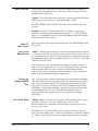
MODEL 5240 ELECTRICAL I/O
The following is a description of the electrical Input/Output. All connectors are contained on the rear panel of
Model 5240.
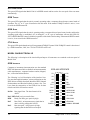
GPIB INTERFACE
Computer to instrument interconnection uses the standard
IEEE-488 Instrument Cable available from instrumentation
cable manufacturers, computer hardware outlets, Magtrol,
Inc., or Hewlett Packard dealers.
The following is a brief description of the interface lines.
For more thorough information, various publications on the
IEEE-488 are available from Intel, Motorola, IEEE, National
Semiconductor and Hewlett Packard, to name a few. Two
bytes form the composition of the GPIB, 8 bits for data
transfer and 8 bits for interface control.
D1-D8
Data signal lines. The data format is 8 bit
ASCII.
DAC, RFD, DAV are byte transfer lines:
IEEE-488 INTERFACE
D1
1 13
D5
D2
2 14
D6
D3
3 15
D7
D4
4 16
D8
EO1
5 17
REN
DAV
6 18
DAV-COM
NFRD
7 19
NFRD-COM
NDAC
8 20
NDAC-COM
IFC
9 21
IFC-COM
RFD
Ready For Data, goes passively high.
SRQ
10 22
SRQ-COM
DAV
Data Valid - an instrument may signal that its
data is valid by pulling this line low.
ATN
11 23
ATN-COM
SHIELD
12 24
SIGNAL GROUND
DAC
14
Data Accepted - will go passively high,
signaling that the data has been accepted.
Magtrol 5240: Controls, LEDs and I/O
ATN, IFC, SRQ, EOI, REN are bus management lines that control the orderly movement of information
across the interface lines:
ATN
(Attention) monitored continually, and a change results in activation of the transmit/receive
control signals.
IFC
Interface clear - used by the system controller to place the GPIA (General Purpose Interface
Adapter chip) into a known quiescent state.
SRQ
Service request signals a need for service by requesting the controller to interrupt the current
sequence of events.
REN
Remote Enable - selects an alternate source for device programming data. This converts the
GPIA into another state of operation.
EOI
End or Identify - has a dual purpose. It may signal the end of a multibyte transfer, or when used
in conjunction with ATN, places the contents of the parallel poll register on the bus.
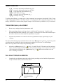
DYNAMOMETER BRAKE
Model 5240 applies power to the dynamometer load brake through a cable fitted with
Cinch type, 2 pin connectors. These lines connect directly to the dynamometer hysteresis
brake coil in Magtrol Dynamometer Models HD-100, HD-106, HD-400, HD-500, HD700 and HD-705. On Models HD-800 and up (HD-8XX), an intermediate booster power
supply is contained within the dynamometer cabinet. The applied voltage is 0-28 VDC, at up to 0.7 amps,
dependent on dynamometer size.
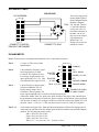
ACCESSORY TORQUE-SPEED OUTPUT
This is an output only connector. It is used to provide input to other Magtrol
Digital Torque-Speed products. The connector is a standard 7 pin DIN type.
D.P. Pin 7, D.P. Pin 3: These are decimal point locator lines. They have
pull-up resistors to +5VDC. Each individual dynamometer will have the
appropriate line connected to ground that codes the decimal point location
for Model 5240 and other Magtrol products. The decimal point locator code
is:
ddd.d = Pin 7 HI, Pin 3 HI.
dd.dd = Pin 7 LO, Pin 3 HI.
d.ddd = Pin 7 HI, Pin 3 LO.
TACH.
COMMON
TACH.
SIGNAL
6
1
4
TORQUE
COMMON
D.P.
7
3
2
D.P.
5
N/C
TORQUE
OUTPUT
Tachometer Signal: This is a TTL compatible standard frequency output of 60 pulses per shaft revolution.
Outputs of 600 or 6,000 pulses per revolution are available on special order. The tachometer common is chassis
ground.
Torque Output: This is a bipolar analog voltage. The torque common is chassis ground. The torque signal
amplitude varies with the individual dynamometer connected to Model 5240. The signal is equal to the whole
number of the torque value (identified on the dynamometer front panel) in millivolts. Positive polarity would
indicate torque applied in CW direction of rotation. For example: for an HD-700-6 with full scale torque applied
in a CW direction, torque = 425 oz.in. and 0.425 volts between pins 4 and 2, with pin 2 positive.
Magtrol 5240: Controls, LEDs and I/O
15
ACCESSORY CABLE
P/N 88CS089
14 PIN RIBBON
1
8
2
9
3
10
4
11
5
12
6
13
7
14
CONNECT TO DIGITAL
READOUT INSTRUMENT
The cord set required to
connect Model 5240 to
another Magtrol Digital
Readout is Magtrol
P.N. 88CS09. This has
a 7 pin DIN connector
on one end, with a 14
pin ribbon connector on
the other. Do not use
this cord set to connect
a dynamometer to
Model 5240. No
damage will result, but
nothing will work!
7 PIN
6
7
1
4
3
2
5
CONNECT TO 5240
DYNAMOMETER
Model 5240 connects to any Magtrol dynamometer with a 14 pin ribbon connector.
Pin 11
Pin 10
is a spare 10 VDC used in older
dynamometers.
is the tachometer frequency signal
providing 60 pulses per shaft
ISOLATED
revolution. The signal level has a
22 VDC
low voltage of approximately 0.2,
and a signal high of 5.0 + 0.1 VDC. ISOLATED
The common to this signal is Pin 8.
22 VDC
N/C
N/C
+
+
-
1
8
2
9
3
10
4
11
5
12
6
13
7
14
COMMON
D.P.
TACH. SIGNAL
(SPARE) +10 VDC
D.P.
TORQUE COMMON
Pin 14
TACH. +5.0 VDC
TORQUE SIGNAL
is the millivolt level torque signal,
referenced to Pin 13. This is a
bipolar analog voltage. Pin 13
CONNECTOR SHELL
(common) is chassis ground. The
& CABLE SHIELD
torque signal amplitude varies with the individual dynamometer
connected to Model 5240. It is equal to the whole number of the torque value (identified on
the dynamometer front panel) in millivolts. Positive polarity would indicate torque applied in
CW direction of rotation. For example: an HD-106-6 with full scale torque applied in a CCW
direction, torque = 2.50 oz.in. = 0.250 volts between pins 14 and 13, with pin 14 negative.
Pins 9 - 12
are decimal point locator lines. Each individual dynamometer will have the appropriate line
connected to ground that codes the decimal point location for Model 5240 and other Magtrol
products. The decimal point locator code is:
ddd.d = Pin 9 N/C, Pin 12 N/C.
dd.dd = Pin 9 LO, Pin 12 N/C.
d.ddd = Pin 9 N/C, Pin 12 LO.
Where N/C = no connection, LO = Common to Pin 8.
16
Magtrol 5240: Controls, LEDs and I/O
Pin 7
is 5.0 VDC for the TACH LED/Phototransistor. It references common to Pin 8 as shown.
Pins 3-6
are 20 VDC isolated instrumentation voltages for the torque signal amplifiers and the torque
load cell power supply. Within the dynamometer enclosure, these unregulated voltages are
converted to regulated + 15 VDC and regulated + 5.0 VDC for the dynamometer torque
transducer load cell. Your Dynamometer User’s Manual Chapter 4 covers this in greater
detail.
OPERATING INSTRUCTIONS
NOTE: Please refer to the Instruction Set description in Section 3 for a complete listing and description of
all available instructions.
MANUAL TORQUE CONTROL
Preset the TORQUE knob fully CCW and the BRAKE ON/OFF switch ON. Turn the power ON. The CTLS
ACTIVE LED should illuminate, indicating that the controller is in the manual TORQUE control mode.
The CURRENT GAIN control is adjusted to supply dynamometer coil current sufficient to provide rated shaft
torque. This is set as follows:
1.
Attach the Calibration Beam supplied with your Dynamometer to the load shaft. The Calibration
Beam is simply a moment arm that converts a force from a weight hung at a specific distance to a
calibrated torque applied to the load shaft. The load torque is the weight times the moment arm
distance. See the sketch in the FULL SCALE TORQUE CALIBRATION paragraph on page 22.
For example, an HD-705 is rated 50.0 lb.in. load torque. Hanging a 5.00 lb. calibrated weight at the
10 inch pin of the Calibration Beam applies the rated torque of 50.0 lb.in. to the dynamometer shaft.
The Calibration Beam is marked in inches for an English system of units or centimeters for metric.
2.
Set the front panel manual TORQUE control for maximum torque - fully clockwise. Set the
CURRENT GAIN control (outer knob of GAIN control cluster) for minimum current fully counterclockwise.
3.
Slowly increase the CURRENT GAIN control clockwise while holding the calibration weight on the
Calibration Beam's hanging pin until the dynamometer torque is just sufficient to support the weight
when the beam is horizontal. The Calibration Beam should be positioned horizontally as determined
by the bubble sight glass located at the center of the Calibration Beam.
Make a note of the position of the CURRENT GAIN control knob for future calibration reference.
The controller is now calibrated to supply full dynamometer load torque when the manual TORQUE
control knob is set fully clockwise. This calibration is also active when operating the controller from
computer control. Therefore, this setting should be maintained in both MANUAL and COMPUTER
control modes.
NOTE: The CURRENT GAIN control setting can be modified from the calibrated setting to
achieve optimum control response while running an automated motor test curve. This will not affect
the calibration numbers, only the control response. If a readjustment has been made, return the
CURRENT GAIN knob setting back to the calibrated reference position when the test is completed.
Magtrol 5240: Controls, LEDs and I/O
17
Adjusting the TORQUE control knob will apply an adjustable torque load to the test motor. Set the motor load
as desired within the dynamometer and motor specifications.
The GAIN, ERROR and STABILITY controls are non-functional since they are speed control adjustments.
Manual torque control can be started from the GPIB TORQUE or GPIB SPEED control modes by sending an
“R” (reset) GPIB instruction.
NOTE: Be careful not to stall or overload the motor, as damage to your motor could result.
GPIB TORQUE CONTROL (COMPUTER CONTROL)
Set the CURRENT GAIN control as described in the MANUAL TORQUE CONTROL paragraph, above.
To initiate GPIB computer interface control, enter the “M0” (M zero) command. The CTLS ACTIVE LED will
extinguish, and the GPIB TRANSFER LED will illuminate. A torque control value (within the ratings of your
dynamometer and motor) can be set by sending the “Qdd.dd” instruction (dd.dd is the torque value). The GPIB
TORQUE, GPIB TRANSFER and DYNO BRAKE LEDs should illuminate. Use the “Q” instruction to remove
(zero) the torque load. The GPIB TORQUE and DYNO BRAKE LEDs will extinguish, and the GPIB TRANSFER
LED will illuminate.
When in GPIB TORQUE control, other modes can be entered as follows:
MANUAL TORQUE control can be restarted by using the “R” (reset) instruction, the CTLS ACTIVE LED
should illuminate. See the MANUAL TORQUE control section, above.
MANUAL SPEED control can be started using the “R” (reset) instruction, followed by sequencing the BRAKE
ON/OFF switch OFF and ON. The AUTO RANGE LED should illuminate. See the MANUAL SPEED
CONTROL section, below.
GPIB SPEED control can be started from the MANUAL SPEED control mode by using the “M0” (M zero)
instruction. See the GPIB SPEED CONTROL section, below.
MANUAL CONTROL
The controller’s AUTO RANGE feature will establish the speed range calibration as follows:
1.
Preset the PID control knobs as shown:
SPEED - fully CW
GAIN - to approximately the 9:00 o’clock position
ERROR - to approximately the 9:00 o’clock position
STABILITY - to approximately the 9:00 o’clock position
2.
Sequence the BRAKE ON/OFF switch OFF and ON. The AUTO RANGE LED will illuminate. This
uses the controller’s auto range capability to establish the speed range at the free run motor speed.
The speed control range is now set from near locked rotor (zero) to the free run speed. As long as the
BRAKE switch remains ON, the set speed range will remain in effect.
3.
Rotate the SPEED control knob CCW to apply a load torque to the brake, slowing and controlling
motor speed at the set value. Continue to slowly turn the SPEED control CCW through the desired
18
Magtrol 5240: Controls, LEDs and I/O
speed range and observe its performance. If the motor speed is unstable (oscillatory) or if you wish to
fine tune the controller for optimum performance, see the PID control loop setting procedure below.
Setting the PID Control Loop for Optimum Performance
These adjustments should be made after the speed range has been set (see step 2 above).
A.
If the motor speed is oscillatory, rotate the STABILITY control to achieve stability. If good stability
cannot be achieved, reduce the GAIN setting and readjust the STABILITY control. Work back and
forth between the STABILITY and GAIN controls to achieve good stability. If the speed response is
too slow, increase the GAIN control CW and readjust the STABILITY control to maintain stability.
B.
With a stable motor, peak performance can be obtained by adding more proportional GAIN (CW)
and readjusting the STABILITY control as necessary to maintain good motor stability. Add some
integral by turning the ERROR control a little CW, and readjust the STABILITY control as necessary
to maintain good motor stability. Work back and forth with the GAIN, STABILITY and ERROR
controls to optimize motor response performance. A little experimentation will be necessary to get
the feel of the adjustment effects. The goal is to achieve settings of the GAIN and ERROR controls as
far CW as possible and still have good motor stability throughout the desired motor speed range.
The higher (CW) the GAIN is set, the more responsive the control will be, and the higher (CW) the ERROR
control is set, the closer the speed will be held to the set point value. The best PID control loop settings will be
achieved by alternately working back and forth with the above controls, while varying the motor speed through
the desired speed range.
GPIB SPEED CONTROL (COMPUTER CONTROL)
1.
Set the speed PID loop controls of GAIN, ERROR and STABILITY, as in manual speed control
mode, above. These manual speed control settings are a good starting point for the GPIB speed
control mode settings. From these, you can fine tune the GAIN, ERROR and STABILITY settings as
needed to achieve the desired response. If the speed control range under the GPIB mode runs from
near locked rotor to free run, make sure that you manually vary the speed from free run to near zero
speed while making your manual speed settings. The wider the desired speed control range, the more
critical the PID control settings become, i.e. to control from near locked rotor to free run requires the
most fine tuning.
2.
From the Manual Speed Control Mode, use the “M0” (M zero) instruction to start the GPIB computer
speed control mode. The GPIB TRANSFER and GPIB SPEED LEDs should illuminate.
3.
Establish an operating speed control range by using the “Fddddd” instruction, where ddddd is a
specific range value between 256 and 32,000. The AUTO RANGE LED will extinguish. In general,
you will want to set the speed range to the free run speed of your test motor.
The operating speed range can also be set by using one of the five preprogrammed ranges as shown:
Instruction “A” sets the range to 2,000 RPM.
Instruction “B” sets the range to 4,000 RPM.
Instruction “C” sets the range to 8,000 RPM.
Instruction “D” sets the range to 16,000 RPM.
Instruction “E” sets the range to 32,000 RPM.
Magtrol 5240: Controls, LEDs and I/O
19
4.
Speed set points are set by using the “Nddddd” instruction. The SPEED SYNC LED illuminates
when the set point is reached. If the SPEED SYNC LED fails to illuminate, the speed is not within an
acceptable error from the set value. If this happens, try increasing the GAIN and ERROR control
settings (CW). If the SPEED SYNC LED flashes on and off, the motor is oscillating. The
STABILITY control setting should be increased (CW) and the GAIN control may possibly need to be
reduced (CCW) to achieve stability.
5.
To cancel an existing speed range (GPIB SPEED LED is on), use the “N” instruction. This
instruction sets the speed range to the maximum range of 32,000.
6.
From GPIB SPEED CONTROL Mode, other modes can be entered as follows:
GPIB TORQUE control can be started by using the “N” and “Qdd.dd” instructions. See the GPIB TORQUE
control operating instructions, above.
MANUAL TORQUE control can be started by using the “R” (reset) instruction. See the Manual Torque
control operating instructions, above.
MANUAL SPEED control can be started by using the “R” (reset) instruction, followed by sequencing the
BRAKE ON/OFF switch off and on. See the Manual Speed control operating instructions, above.
20
Magtrol 5240: Controls, LEDs and I/O
5 - Calibration
Calibration and balancing controls are provided for most of the analog elements in Model 5240. Normally, no
adjustment of these elements is anticipated for the life of the instrument. All or part of the calibration and
balancing procedures may be indicated, however, if any of the following conditions exist:
•
•
Slight torque loading, with the DYNO BRAKE LED ON, when not called for.
•
A torque difference between CW and CCW full scale readings of greater than 2 least significant digits in
standard resolution.
A torque difference between the GPIB indicated value and another Magtrol Digital Readout of greater
than + 0.25%.
There is no calibration for the digital speed reading. Please refer to MODEL 5240 SPECIFICATIONS in this
chapter.
BEFORE PROCEEDING
Routine Torque calibration and zero offset adjustments should always be done using your dynamometer. The
torque signal offset and calibration controls within Model 5240 are provided to permit standardization with
other Magtrol Digital Readouts, as well as agreement between full scale values in both CW and CCW directions.
The torque value produced by the dynamometer should read within tolerance on all instruments. If a dissimilarity
exists between Model 5240 and another digital readout, before proceeding with zero offset or calibration
adjustments, you must establish which of the two instruments requires the service adjustment. This must be
done first, by standardization of the dynamometer signal output.
WARNING!
The following requires removal of Model 5240’s top cover. All connections and trimpot
adjustments must be made only as specified herein and with caution. There is an electrical
shock hazard inside Model 5240. Do not touch or connect instrumentation to any elements of
the circuit boards, front panel or chassis components.
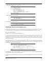
C3
All calibration and balancing potentiometers are contained on the circuit board identified 78B159. This is located
in the lower left corner of Model 5240’s chassis, facing from the rear panel. The following sketch shows the
portion of the board on which the trimpots are located, their identification and function.
C6
R1
C4
R4
J2
R9
Qc
5
Qb
R5
6
D1
R12
C9
RN1
U13
C68
U16
C72
U19
1
C8
R8
R10
D2
R18
R13
R14
4
R16
2
R17
3
+Qb +Qc -Qb -Qc
C10
C7
R15
U5
D4
C63
U8
J1
C74
78B159 PCB
Magtrol 5240: Calibration
21
TRIMPOT FUNCTION
Qc R1 - Accessory output torque calibration (Q0 Cal).
Qb R4 - Accessory output torque signal zero (Q0 Bal).
-Qc R10 - CCW torque full scale calibration (-QCal).
-Qb R8 - CCW torque zero (-QBal).
+Qc R14 - CW torque full scale calibration (+QCal).
+Qb R16 - CW torque zero (+QBal).
To perform the following, you must write a short, continuous loop program to have Model 5240’s Torque
output reading displayed by the controlling computer. All references to “CRT” in the following pertain to this
reading. APPENDIX A contains a short program example, CONTINUOUS Q-N DISPLAY, for your reference.
TORQUE ZERO (NULL) ADJUSTMENT
1.
Remove any couplings from the dynamometer shaft.
2.
Place a precision voltmeter resolving at least 0.1 millivolt (DC) between pins 13 and 14 on the
DYNAMOMETER ribbon connector, pin 13 negative. You may have to remove the connector cap on
the cable or obtain access from inside the dynamometer rear panel.
3.
Adjust the dynamometer zero control for best zero (dynamometer torque signal output) on your
voltmeter.
The object of the following step is to alternate between the - and + Bal trimpots (-Qb and +Qb, respectively), until
you know that each is adjusted so that your output torque reading is JUST at zero - on both trimpots.
While observing, Model 5240’s Output Torque Reading (CRT):
4.
Adjust the + Q Bal trimpot (+Qb , R16) 1 slowly. Try both CW and CCW rotation until the indicated
torque value reads higher, then back off very slowly until the reading is zero or returns to the original
value. Repeat this procedure on the - Q Bal trimpot (-Qb , R8) 2 . Work back and forth to set zero
with a 1 flashing occasionally.
FULL SCALE TORQUE CALIBRATION
1.
Complete the zero adjustment procedure outlined in the preceding section. Install the Dynamometer
Torque Calibration beam, as shown in the sketch.
Torque = Weight (W) x Distance (D)
Weight (W) = Torque / Distance (D)
D
W
22
Be sure the shaft flat is facing down,
tighten the cal-beam screw against the
shaft flat only.
Magtrol 5240: Calibration
2.
With Model 5240 in MANUAL TORQUE mode, turn on the BRAKE switch. Rotate the TORQUE
control full CW for maximum applied torque. With a precision weight, apply a known torque at or
close to full scale in the CCW direction. Maintain the beam exactly horizontal and perfectly still.
3.
Observe the voltage reading (across pins 13 and 14) on the voltmeter. Adjust the TORQUE CALIB
on the rear panel of the dynamometer for a voltmeter (millivolt) reading exactly equal to the true
torque applied.
4.
Adjust the - QCal trimpot (-Qc, R10) 3 until Model 5240’s output (CRT) torque reading is equal to the
voltmeter reading.
5.
Place the weight on the opposite side of the beam. Adjust the + QCal trimpot (+Qc, R14) 4 to match
Model 5240’s output (CRT) torque and voltmeter reading.
NOTE: As you changed the torque direction, if there is an excessive CW to CCW difference (greater than 2
LSD at standard resolution), this may indicate a need to adjust the pivot bearing assembly within the dynamometer.
Before doing this, however, be sure your voltmeter repeats a reading after a polarity reversal. Many do not.
Please consult Dynamometer Customer Service at Magtrol before attempting mechanical alignment of the
dynamometer pivot assembly.
ACCESSORY TORQUE OUTPUT CALIBRATION
With zero torque applied to the dynamometer and nothing connected to the shaft:
1.
While reading Model 5240’s output (CRT) torque value, adjust the dynamometer ZERO control for
best zero reading.
2.
With a voltmeter, resolving at least 0.1 millivolt DC, connected between pins 2 and 4 on the
ACCESSORY TORQUE-SPEED OUTPUT connector, or using the Magtrol Digital Readout
Instrument, adjust the Q0 Bal trimpot (Qb, R4) 5 for best zero reading.
3.
Attach a Calibration beam. Energize the brake to hold the beam. Attach a weight to apply an amount
of torque close to the dynamometer full scale rated value. Adjust the Q0 Cal trimpot (Qc, R1) 6 for
the correct torque reading.
MANUAL TORQUE CONTROL ZERO
1.
At zero RPM, rotate the TORQUE control 1/2 turn CW (ON).
2.
Rotate the TORQUE ZERO trimpot R33 until the DYNO BRAKE LED just goes ON, then CW until
it just goes OFF.
GPIB "Q" COMMAND TORQUE NULL
1.
Output an “I16” command to Model 5240.
2.
If the DYNO BRAKE LED is OFF, no adjustment is necessary. If the DYNO BRAKE LED is ON,
adjust the Q trimpot until the LED just goes out.
This completes the balancing and torque calibration procedure.
Magtrol 5240: Calibration
23
MODEL 5240 SPECIFICATIONS
SPEED CONTROL
OUTPUT:
DC speed control current up to 0.75 amps.
ACCURACY:
+ 0.05% of the SPEED reading.
RESOLUTION (in RPM):
RANGE
0 to 4,000
0 to 8,000
0 to 16,000
0 to 32,000
RESOLUTION
1.0
2.0
4.0
8.0
TORQUE CONTROL
OUTPUT:
DC torque control current up to 0.75 amps.
ACCURACY:
Determined by the accuracy of the dynamometer in use. Please refer to your
Magtrol Dynamometer User’s Manual for detailed specifications.
POWER:
120 Vrms or 240 Vrms, 48 to 63 Hz at 120 volt amps.
A WORD ON SPEED VARIATIONS
Instantaneous speed measurements, required for rapid data acquisition, produce some aspects of motor shaft
velocity not normally encountered with typical averaging methods of RPM indication.
A factor encountered in most induction motors, and all motors to some extent, is the lead/lag of the rotor in
relation to the magnetic field that pulls it. You might visualize the rotor connected to the pulling force by a
rubber band, resulting in a slow rotational oscillation, rate dependent upon the rotor’s inertia and other factors.
This is a change in velocity occurring within a single revolution.
With velocity measurement extracted from only a few degrees of rotation, and not necessarily in a fixed radial
position (speed is variable), the measurement window will occur at random locations of the rotor’s angular
position. Therefore, when a reading is “snapshot,” it may be higher or lower than the longer term averaged
speed.
These combinations can produce velocity variations, appearing as data scatter. These may occur rapidly or
sometimes very slowly.
One of the more startling examples occurs when a synchronous induction motor displays a motor speed greater
than the synchronous speed! No, this is not an inaccuracy, and not to despair, if the data is averaged over a
sufficient time period, such as one to two seconds (10 or 20 readings is usually adequate), the variations will
integrate, resulting in an RPM precisely equal to the synchronous speed.
While we may not like these variations, they really represent what the motor is doing within the short time frame
we use to control and produce data.
24
Magtrol 5240: Calibration
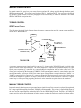
6 - Circuit Description
TACHOMETER
Simultaneous analog and digital speed data is required for proper function of Model 5240. Digital format is
required for RPM as data, analog for the dynamometer speed control signal. Both signals must be highly responsive
and noise free.
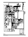
PCB No. 78B156 is the tachometer section which produces this speed information. It uses a clock which is gated
on-off by the period of time between pulses generated by the tachometer generator. Because of the overall RPM
range (0-32,000), the time period must be selectively staged and is dependent upon the immediate shaft speed between 1, 1/10 or 1/60 of a shaft revolution.
Since RPM is now a reciprocal value, a math function is required to convert the value back to true RPM. All
functions are under command of a microprocessor that performs ranging decisions, math and calibration processes
in microseconds.
The block diagram identifies the basic elements. The MPU section contains a Programmable Read Only Memory
(PROM) and Peripheral Interface Adaptor (PIA) for program and I/O control. It also contains buffers and other
“hand-shaking” elements.
FREQ. RATIO SELECT
U24
U3-1
U4-1
DYNO. TACH-GEN
U27
U26
U6-40
U4-12
U25
U17
U1
U18
U6
U2
U19
MPU
U5
U20
U7,9,10
COUNTER
I
FREQ
78B156 PCB
CLOCK
1 MHz
PIN 12
U16
PIN 11
U15
SPEED
OUTPUT
16 BIT
PIN 15
0-5 VDC
SPEED
ANALOG
SIGNAL
PB6
RANGE CONTROL
PB7
The speed transducing function is complex, and only elemental measurements for adequate power supply voltages
and speed signal output may be done easily. The analog speed output signal may be measured between pin 15
and 17 on U15. This voltage is between 0 to 5.0 VDC, full scale, for each speed range. If a voltage proportional
to speed is present here, you can reasonably assume that everything in the speed section is working properly.
Magtrol 5240: Circuit Description
25
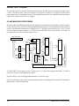
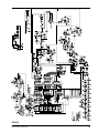
SPEED CONTROL
GPIB SPEED CONTROL
This functional block diagram shows the speed PID control section and the current output amplifier, both located
on PC board 78B159.
(DIFFERENTIATOR)
SPEED SIGNAL
(Na)
(FROM D/A CONV. U15
ON 78B156 PCB)
(SCALING
AMP)
U27a
U24
C
R60
SPEED
U27b
(ERROR
AMP)
(CURRENT AMP)
35VDC
++
U27c
+
R49
SPEED SETPOINT
Nref
(FROM D/A CONV. U12
ON 78B155 PCB)
PROPORTIONAL
GAIN
U23c
(INTEGRATOR)
C
R72
(0 to 35VDC at
.75 AMP MAX.)
DYNAMOMETER
BRAKE COIL
STABILITY
(SCALING
AMP)
U28
R62
78B159 PCB
U22
Q3
CURRENT
GAIN
.5Ω
CURRENT
SAMPLING
RESISTOR
R71
ERROR
The calibrated speed signal, Na, from D/A (digital to analog) converter U15 (located on the 78B159 PC board)
and the speed command set point Nref from D/A converter U12 (located on the 78B159 PC board) are algebraically
summed and amplified by operational amplifier U27c. The amplification of this speed error signal is controlled
by the front panel proportional GAIN control potentiometer R60. This speed error signal feeds an integrating
operational amplifier U28. The amount of integral signal is adjusted by the front panel integral ERROR control
potentiometer R62. Brake current is sampled by a 0.5 ohm series resistor, amplified and differentiated by operational
amplifier U24. This derivative signal is proportional to the rate of change of brake current and acts as negative
rate feedback to provide stability and response shaping. The amount of rate feedback is adjusted by the front
panel derivative STABILITY control potentiometer R71. Then, the proportional speed error signal from U27c, the
integral signals from U28 and the derivative signal from U24 are algebraically summed by operational amplifier
U23c to produce the PID (proportional plus integral plus derivative) control signal. This PID control signal is
input to a current feedback amplifier composed of operational amplifier U22 and bipolar power transistor Q3,
both connected in a current feedback configuration with the brake control coil. This same current amplifier is
utilized during manual and computer torque control. The current amplifier gain is adjusted using front panel
potentiometer R72. This PID current signal modulates the torque (torque from a hysteresis brake is proportional
to brake current) applied to the test motor to achieve closed loop speed control of the test motor. For example,
if the motor speed is above the set speed, the PID loop increases brake current until the increasing applied torque
causes the motor to run at the lower set speed. Conversely, if the motor speed is less than the set value, the PID
loop reduces brake current until the reducing applied torque causes the motor to run at the higher set speed. Any
deviation from the set speed causes the PID control loop to apply a compensating current to correct for the
deviation. The time response and amount of this correction are determined by the settings of the GAIN, ERROR
and STABILITY controls.
26
Magtrol 5240: Circuit Description
MANUAL SPEED CONTROL
In manual control, the speed set point comes from a regulated DC voltage applied through the front panel
SPEED potentiometer R49. This signal is used in place of the Nref signal from the U12 D/A converter as described
by the above GPIB SPEED CONTROL paragraph. Circuit functionality is otherwise identical to the GPIB
SPEED CONTROL description above.
TORQUE CONTROL
GPIB TORQUE CONTROL
The following functional block diagram shows the torque control section and the current output amplifier,
located on PC Board 78B159.
TORQUE
R48
(CURRENT AMP)
+35VDC
(0 to 35VDC at
.75 AMP MAX.)
U22
Q3
TORQUE SETPOINT
(FROM D/A CONV. U19
ON 78B159 PCB)
R72
DYNAMOMETER
BRAKE COIL
CURRENT
.5Ω
SENSE
RESISTOR
78B159 PCB
CURRENT
GAIN
A computer-generated torque signal from D/A converter U19, located on the 78B159 PC board, is applied at the
input of a linear current output amplifier. The current amplifier is composed of operational amplifier U22 and
bipolar power transistor Q3, connected in a current feedback configuration with the brake control coil. The
current gain is adjusted by the front panel CURRENT GAIN potentiometer control R72 (outer knob) to provide
rated dynamometer shaft torque for full D/A control input voltage. When a torque instruction ("Qdd.dd " or
"Idddd") is entered, the D/A converter's (U19) output is adjusted by the microprocessor to provide a voltage input
to the current amplifier to produce the torque value (dd.dd or ddddd) of the instruction. Therefore, a digital
control loop is closed, providing regulating load torque at the instruction set point value to the test motor.
MANUAL TORQUE CONTROL
In manual control, the microprocessor-generated torque signal from the D/A converter is replaced by a regulated
DC voltage applied through the front panel TORQUE potentiometer R48. This voltage is applied to the input of
the same current output amplifier as described above for the GPIB TORQUE mode. Therefore, the TORQUE
control provides an open loop adjustment of brake current to produce the load torque applied to the test motor.
Magtrol 5240: Circuit Description
27
SALIENT POLE "COGGING"
If a specified torque level cannot be maintained (stalled motor), then the system will saturate and load the brake
- full on. A hysteresis brake, with current applied, in the absence of rotation, will temporarily exhibit salient
poles when the power is subsequently removed. Your Magtrol Dynamometer User’s Manual contains a description
of this effect, sometimes referred to as “cogging.”
I/O AND MAIN DATA PROCESSING
The primary MPU and GPIB controlling electronic functions are contained on PC board 78B155. On this assembly,
U5 is the microprocessor, and U10 is the Programmable Read Only Memory containing the Model 5240 operating
system. A 2K nonvolatile RAM device is identified as U11. The N-D/A speed reference D/A is U12. U13 and
U14 are Peripheral Interface Adapters. U1, U2 and U3 are the GPIB interface control elements. The balance of
the components are buffer and timing control devices.
GPIB CONNECTOR
PROGRAM ROM
J3
PIA N
XTAL
4.0 MHz
U10
MPU
CLOCK
1 MHz
PIN 4C
U13
U5
U3
RAM 2K
U1
U11
PIA Q
PIN 15
U2
U14
U12
GPIB INTERFACE
N
D/A
GPIA CONTROLLER
J1
0-5VDC
SPEED REF.
40 PIN I/O CONNECTOR
PC board 78B157 power supply provides +5 logic power, +15 volts for the analog elements and a 35 VDC-50
watt source of power for the dynamometer brake.
Hysteresis brakes, used on all Magtrol Dynamometers, are 28 VDC units.
If you have questions or require more detailed information, please contact Magtrol Customer Service Department,
Dynamometer Technical Information.
28
Magtrol 5240: Circuit Description
APPENDIX A
rogramming Examples
A:: P
Programming
MAGTROL MOTOR TEST SOFTWARE
Magtrol offers, as an option, a comprehensive motor
test software package available on either 3-1/2" floppy
disks or CD-Rom. To demonstrate the capabilities of
this package, a free demo disk is also available. For
further information, or a copy of the demo disk, contact
Magtrol Sales at 716-668-5555 or visit our web site at:
www.magtrol.com
Most people involved in computer programming are familiar with BASIC. In order to show the programming
techniques as simply as possible, all of the following examples are given in Microsoft 4.5®, using a National
Instruments GPIB-PC2A interface.
If you are using another IEEE-488 interface system, modification of the assembly language CALL subroutines
will be required.
Except for the SPEED-TORQUE CRT DISPLAY program, immediately following, the primary address used in
all examples is the default factory setting of 9. If you modify the code switch setting, you will have to correct the
“dev9” operands to reflect this change. Look for the line BDNAME$ = “dev9” and modify the 9 to whatever you
selected, i.e. 1 through 15.
SPEED-TORQUE CRT DISPLAY
In the following example, the program will ask for the GPIB primary address. If you have not changed it, enter
9, and the speed-torque values should display on the CRT, updating continuously:
'$INCLUDE: 'c:\gpib-pc\qbasic\qbdecl.bas'
CLS : LOCATE 10, 20
INPUT “Enter the primary address (1-15)...”, an$
BDNAME$ = “DEV” + an$
CLS
CALL IBFIND(BDNAME$, BD%) ‘Initialize the GPIB
rd$ = SPACE$(15) ‘Dimension the input
DO:
CALL IBRD(bd%, RD$)
spd = VAL(MID$(rd$, 2, 5)) ‘Extract N
tor = VAL(MID$(rd$, 8, 5)) ‘Extract Q
LOCATE 10, 20: PRINT “Speed = “; spd
LOCATE 11, 20: PRINT “Torque = “; tor
LOCATE 20, 50: PRINT “Any key ends...”
LOOP WHILE INKEY$ = “”
SYSTEM : END
Magtrol 5240: Programming Examples
29
RECALL MODEL 5240 DATA FROM MEMORY
If a PDddS or PUddS instruction was issued, all data from the test run will be retained in Model 5240’s memory,
provided that the total test time did not exceed 50 seconds (500 test points @ 0.1 sec.) Another PDddS/PUddS
instruction will append data to that already in Model 5240’s memory. The memory is cleared only when an “O”
command is issued and the data transfer successfully completed.
In the following program fragment, the variable QNdata$ receives the test data from Model 5240 memory. The
data format is similar to that shown on page 2-3, except that the shaft direction character (L or R) is eliminated.
Each individual test point block is always 12 characters long.
'$INCLUDE: 'c:\gpib-pc\qbasic\qbdecl.bas'
‘Routine to access Model 5240 Memory after a PDddS or PUddS command
CLS
BDNAME$ = “DEV9”
eos$ = CHR$(13) + CHR$(10) ‘assign the CR-LF
QNdata$ = SPACE$(6502) “Make room for torque-speed data
wrt$ = “O” + eos$’O+CR-LF command to 29B
CALL IBFIND(BDNAME$, BD%) “Initialize the GPIB
CALL IBWRT(BD%, wrt$) ‘Output command :
CALL IBRD(BD%, QNdata$) ‘Fetch all memory
‘QNdata$ now contains all Model 5240 test data...
What you have is a long data string structured as shown in the following example. To fill in some numbers
for our example, let’s assume a speed of 1752 RPM and 85.64 oz.in. torque. A block of 3 data samples,
anywhere in the string will look like:
.......S01752T85.64S01752T85.64S01725T85.64......
One simple method to extract individual data points would be to create a FOR-NEXT loop to “walk through” the
single variable labeled “QNdata$.” Within the loop, assign two numerical data arrays, one for “Speed” and one
for “Torque.” Since it is unlikely that all the memory was filled with data, zeros will be outputted where the test
stopped. You could omit these by making the array assignment conditional on both torque and speed being
greater than zero. This step is not included in the example.
DIM Speed(600), Torque(600)
n = 1 ‘Initialize array number
FOR l = 2 TO 6005 STEP 12 ‘Step a block at a time
Speed(n) = VAL(MID$(QNdata$, l, 5))
Torque(n) = VAL(MID$QNdata$, l + 6, 5))
n=n+1
NEXT
PROGRAMMING EXAMPLE FOR “I” COMMAND USE
To apply a torque value to the test motor as rapidly as possible, the Idddd command provides a method to
directly address the Q-D/A converter. The I instruction requires that the numerical value used with it be a
number from 1 to 4095. In order to relate this to torque, first output a “Qdd.dd” command, made dd.dd equal to
the value of torque you want (2.0 is selected in the example), delay a few seconds for the system to respond and
30
Magtrol 5240: Programming Examples
settle, then ask for the contents of the Q-D/A converter with the “X” command. Concatenate the number
returned with the I command.
'$INCLUDE: 'c:\gpib-pc\qbasic\qbdecl.bas'
‘Routine to use the “I” command
‘TOR$ = Torque value you wish to emulate with the I command
CLS : eos$ = CHR$(13) + CHR$(10) ‘CR-LF
wrt$ = “Q” + “2.0” + eos$ ‘“2.0” is arbitrary here.
BDNAME$ = “DEV9” ‘primary address = 9
CALL IBFIND(BDNAME$, BD%)
CALL IBWRT(BD%, wrt$) ‘Loading Q2.0 (2.0 units of torque)
SLEEP (7) ‘Wait 7 seconds to settle down
wrt$ = “X” + eos$ ‘Q-D/A Data request
CALL IBWRT(BD%, wrt$)
QDA$ = SPACE$(6) ‘always returns 4 digits + CR-LF
CALL IBRD(BD%, QDA$) ‘D/A converter value
FASTQ$ = “i” + QDA$ ‘+Idddd
CALL IBWRT(BD%,FASTQ$) ‘-this may go anywhere for fast Q loading
PROGRAMMING EXAMPLE FOR “Z” COMMAND USE
To apply a value of speed to the test motor as rapidly as possible, the Zdddd command directly addresses the
N-D/A converter. The Z instruction requires a numerical value of 1 to 4095. To establish this value relative to
the speed you wish to apply, use the Nddddd instruction first. After the speed has settled, out put a “Y” data
request. The 4-digit value returned may then be concatenated with “Z” for fast speed loading.
Be sure that the speed range has been previously established!
'$INCLUDE: 'c:\gpib-pc\qbasic\qbdecl.bas'
‘Routine to use the “Z” command
CLS
eos$ = CHR$(13) + CHR$(10) ‘CR-LF
wrt$ = “N” + “1750” + eos$
BDNAME$ = “DEV9” ‘primary address = 9
CALL IBFIND(BDNAME$, BD%)
CALL IBWRT(BD%, wrt$)
SLEEP (7) : WRT$ = “Y” + eos$
CALL IBWRT(BD%, wrt$)
NDA$ = SPACE$(6)
FASTN$ = “Z” + nda$
CALL IBWRT(BD%,FASTN$) ‘this may go anywhere for quick N loading.
If you have questions regarding any of the above examples, or if you have suggestions regarding software
development, please feel free to contact Magtrol Software Engineering at any time.
Magtrol 5240: Programming Examples
31
APPENDIX B
B:: Inertia Correction
INERTIAL EFFECT ON MOTOR TEST DATA
A major advantage of the Magtrol Speed Controlled System is the ability to obtain full (free run to locked rotor)
motor performance data by continuous load application with an absorption dynamometer. Data acquisition is
fast, resulting in minimal motor I2R losses, and loading characteristics simulate actual end-use applications.
When a motor is accelerating or decelerating, the measured torque is the sum of the true motor torque + the
inertial torque (stored energy) of the system. Unless inertial torque is excluded, motor performance data will be
in error, since the measured torque will vary in proportion to the rate of acceleration/deceleration.
This type of error can produce startling test results. For example, during rapid deceleration, system inertia can
produce apparent efficiency greater than 1.0! This may occur as output power is divided by input power without
extracting the stored energy in the system. Alluding to perpetual motion causes most technically oriented people
to suspect the data.
DATA TIMING FACTOR
Since “inertial effect” is only a factor as speed is changing, and since inertial torque is proportional to the rate of
change, inertial value may be expressed as a unit of torque per change in RPM in a given period of time.
Model 5240 accumulates and outputs test data at fixed intervals of 0.10 second. Therefore, change in RPM
occurs over that fixed period, regardless of test rates. It might seem desirable to output data at fixed intervals of
speed or torque, perhaps every 100 RPMs or some other figure which is easy to work with. But this would
preclude the ability to extract inertial error effects, unless we could somehow accurately measure and rapidly
output the elapsed time between every data point. If you must have speed/torque data in even decades, various
computer software routines provide fast and accurate curve fitting techniques to do this for you.
PROCEDURE
In order to create a torque Correction Factor (CF), we need:
1.
A torque value equal to the inertial torque.
2.
The difference in RPM (per 0.1 sec) that created that value.
In the following graph example, we have arbitrarily selected a data point on the performance curve. We want to
program down by increasing torque load and fetch a group of test points. We have selected the first data point,
where speed will be just less than 78% of the Free Run speed. Call this the dynamic speed value. Additionally,
save one test point before this value and one after. Immediately program Model 5240 (Nddddd) to a speed
exactly equal to this “dynamic” value. When the speed has stabilized, fetch this as the static torque value.
To calculate CF, first average the speed change between 3 test points. Next, calculate the difference in torque
between the static speed value and the dynamic speed value. Divide this torque difference by the average
change in speed. The result is your CF.
32
Magtrol 5240: Inertia Correction
DECLARATION TORQUE
vs. SPEED CURVE
DYNAMIC
TORQUE VALUE
FR
}
.78 OF FR
SPEED
STATIC
TORQUE VALUE
AVERAGE THE CHANGE
IN SPEED BETWEEN
THESE POINTS
DIFFERENCE
IN TORQUE
CF =
DIFFERENCE IN TORQUE
CHANGE IN SPEED
0
TORQUE
A few key conditions:
•
The test point selection of “0.78” is fairly typical for an induction motor. Select this value in an area
where the performance curve is fairly linear, and there is a substantial torque change with speed.
•
The data must be acquired rapidly, so that motor heating does not degrade performance by adding a false
difference between the static and dynamic torque values.
•
The input line voltage must be stable for the 1 or 2 seconds needed to perform the test. Torque varies by
the square of the change in line voltage. Use a regulated power source.
INERTIA CANCELLATION PROGRAM
The following steps outline a computer program, in Quick Basic, to control Model 5240 for the acquisition of
a “CF” value. Initialization:
'$INCLUDE: 'c:\gpib-pc\qbasic\qbdecl.bas'
‘fr = free run speed. You must assign this value.
BDNAME$ = “DEV9” ‘Primary addr = default code 9.
CALL IBFIND(BDNAME$, BD%) ‘Initialize the GPIB.
eos$ = CHR$(13) + CHR$(10) ‘CR-LF termination char’s.
Magtrol 5240: Inertia Correction
33
PROGRAMMING
STEPS
1. With the system up and running, command a PD99 instruction to Program Down to 78% of the free run
speed:
wrt$ = “PD99” + eos$ ‘Program Down at a fast rate.
CALL IBWRT(BDNAME$, wrt$) ‘Send it to Model 5240
rd$ = SPACE$(15) “Assign room for the data + CR-LF
2. Collect data in an array. (Single data point = SdddddTddd.dL.)
X = 0 ‘X is our array # = selected speed point.
DO: X = X + 1
CALL IBRD(BD%, rd$) ‘rd$ is the data from Model 5240
ND(X) = VAL(MID$(rd$, 2, 5)) ‘SPEED
QD(X) = VAL(MID$(rd$, 8, 5))‘TORQUE
LOOP UNTIL ND(X) <.78*fr ‘fr = free run RPM assigned.
3. Set up the static value as an N instruction. Model 5240 will apply it when the current PD99 instruction
terminates. NOTE: An Nddddd will not override an in process PDdd instruction.
wrt$ = “N” + STR$(ND(X)) + eos$ ‘Static speed value.
CALL IBWRT(BD%, wrt$)
4. Save the next N-Q test point < the .78 FR value:
Y = X ‘Keep X intact, change array # to Y.
DO: Y = Y + 1
CALL IBRD(BD%, rd$)
ND(Y) = VAL(MID$(rd$, 2, 5))
QD(Y) = VAL(MID$(rd$, 8, 5))
LOOP UNTIL Y = X + 1
5. Send a “PR” instruction to stop further loading. The system will revert automatically to the “N” value
installed by Step 3 above.
wrt$ = “PR” + eos$ ‘Stop PDdd, revert to static point
CALL IBWRT(BD%, wrt$)
6. Calculate the average difference is speed between the test points. Call it (avgdN).
avgdN = (ND(X-1) - ND(X)) + (ND(X) - (ND(X + 1))
avgdN - avgdN/2
34
Magtrol 5240: Inertia Correction
7. Now wait for the static speed to be equal to the dynamic speed value previously obtained. Hold in a loop
until 3 speed readings agree - just to be sure.
samples = 0 ‘Null it.
DO: CALL IBRD(BD%, rd$)
speed = VAL(MID$(rd$, 2, 5))
torque = VAL(MID$(rd$, 8, 5))
IF speed = ND(X) THEN samples = samples + 1
LOOP UNTIL samples = 2
8. Return the motor to free run speed.
wrt$ = “N” = eos$
CALL IBWRT(BD%,wrt$)
9. Determine the Correction Factor CF.
CF = (QD(X) - torque)/avgdN
CORRECTING TEST RUN PERFORMANCE DATA
The following program fragment shows one method to correct data, using a previously obtained CF. You have
run a complete motor test by PDdd, PUdd or both, acquiring the “SdddddTdd.ddL” type data in an array.
AN = Array counter (number)
Dta$(AN) = Your test run data, a string variable array.
To correct each torque value in the array of test data, you must first subtract each speed test point from the
preceding speed test point value. Call this a numerical variable dN. This number yields the change of speed
occurring in the 0.1 second period for that data point. It will be a signed value, positive if the motor is decelerating,
negative if accelerating.
Next, multiply dN by the CF. We will call the (signed) product CFdN. This is equal to the inertial torque portion
of the torque value for that respective data point. Algebraically sum this with the (test point) torque value, and
place the result in a numerical array, Ttor(AN).
FOR I = 2 TO AN -1 ‘Start with the 2nd value!
dN = VAL(MID$(dta$(I-1), 2,5)) - VAL(MID$(dta$(I), 2, 5))
CFdN = CF * dN
Ttor(I) = VAL(MID$(Dta$(I), 8, 5)) - CFdN ‘torque -/+ inertia.
NEXT
We still have the original test data unchanged. The new data array “Ttor(AN)” contains complete performance
curve torque data, with the effects of inertia removed.
If you have any questions regarding any of the above, please contact Magtrol Customer Service, Model 5240
software.
Magtrol 5240: Inertia Correction
35
APPENDIX C
C:: Drawings
78B155
36
Magtrol 5240: Drawings
78B156
Model 5240: Drawings
37
78B157
38
Magtrol 5240: Drawings
78B159
Model 5240: Drawings
39
Magtrol Limited W
arranty
Warranty
Magtrol, Inc. warrants its products to be free from defects in material and workmanship under normal use and
service for a period of one (1) year from the date of shipment. Software is warranted to operate in accordance
with its programmed instructions on appropriate Magtrol instruments. This warranty extends only to the original
purchaser and shall not apply to fuses, computer media, or any other product which, in Magtrol’s sole opinion,
has been subject to misuse, alteration, abuse or abnormal conditions of operation or shipping.
Magtrol’s obligation under this warranty is limited to repair or replacement of a product which is returned to the
factory within the warranty period and is determined, upon examination by Magtrol, to be defective. If Magtrol
determines that the defect or malfunction has been caused by misuse, alteration, abuse or abnormal conditions
of operation or shipping, Magtrol will repair the product and bill the purchaser for the reasonable cost of repair. If
the product is not covered by this warranty, Magtrol will, if requested by purchaser, submit an estimate of the
repair costs before work is started.
To obtain repair service under this warranty, purchaser must forward the product (transportation prepaid) and a
description of the malfunction to the factory. The instrument shall be repaired at the factory and returned to
purchaser, transportation prepaid. MAGTROL ASSUMES NO RISK FOR IN-TRANSIT DAMAGE.
THE FOREGOING WARRANTY IS PURCHASER’S SOLE AND EXCLUSIVE REMEDY AND IS IN LIEU OF
ALL OTHER WARRANTIES, EXPRESSED OR IMPLIED, INCLUDING BUT NOT LIMITED TO ANY IMPLIED
WARRANTY OF MERCHANTABILITY, OR FITNESS FOR ANY PARTICULAR PURPOSE OR USE. MAGTROL
SHALL NOT BE LIABLE FOR ANY SPECIAL, INDIRECT, INCIDENTAL, OR CONSEQUENTIAL DAMAGES
OR LOSS WHETHER IN CONTRACT, TORT, OR OTHERWISE.
CLAIMS
Immediately upon arrival, purchaser shall check the packing container against the enclosed packing list and
shall, within thirty (30) days of arrival, give Magtrol notice of shortages or any nonconformity with the terms of the
order. If purchaser fails to give notice, the delivery shall be deemed to conform with the terms of the order.
The purchaser assumes all risk of loss or damage to products upon delivery by Magtrol to the carrier. If a product
is damaged in transit, PURCHASER MUST FILE ALL CLAIMS FOR DAMAGE WITH THE CARRIER to obtain
compensation. Upon request by purchaser, Magtrol will submit an estimate of the cost to repair shipment damage.
MAGTROL
70 Gardenville Parkway M Buffalo, New York 14224
Phone: (716) 668-5555 M (800) 828-7844 Fax: (716) 668-8705
www.magtrol.com