1
SAVE THIS MANUAL
FOR FUTURE
REFERENCE
Serial
Number
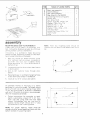
Model and serial
number may be found
at the right-hand side
of the frame.
You should record both
model and serial
number in a safe place
for future use.
IO.INC
SA
CAUTION'.
Read GENERAL and
ADDITIONAL
SAFETY
INSTRUCTIONS
Q
assembly
Q
operating
Q
repair parts
carefully
Sold by SEARS,
Part No. SP5100
ROEBUCK
AND
CO., Chicago,
IL. 60684 U.S.A.
FULL
if within
material
WARRANTY
ON CRAFTSMAN
one year from the date of purchase,
this Craftsman
or workmansh ip, Sears will repair it, free of charge.
WARRANTY
SERVICE
CENTER/DEPARTMENT
THiS
ONE YEAR
WARRANTY
This warranty
state to state.
IS AVAILABLE
THROUGHOUT
APPLIES
gives
ONLY
you specific
BY SIMPLY
CONTACTING
THE UNITED STATES.
WHILE
legal
THiS
rights,
PRODUCT
BAND
Band
THE
iS USED
Saw fails
due to a defect
NEAREST
IN THE
and you may also have
SAW
other
SEARS
UNITED
rights
in
SERVICE
STATES.
which
vary from
SEARS. ROEBUCK AND CO., 698/731A, Sears Tower, Chicago, IL 60684
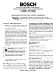
eneral safety instructions for power tools
KNOW YOUR POWER TOOL
Read aria understand
the owner's
manual and
labels affixed to the tool. Learn its application
and limitations
as well as the specific
potential
hazards peculiar to this too!,
2.
3.
4.
5.
6.
7.
8.
9.
GROUND ALL TOOLS
This tool
is equipped
with
an approved
3conductor
cord and a 3-prong
grounding
type
plug to fit the proper grounding
type receptacle,
The green conductor
in the cord is the grounding wire. Never connect the green wire to a live
terminal.
KEEP GUARDS IN PLACE
-- in working
order, and in proper adjustment
and alignment.
REMOVE ADJUSTING
KEYS AND WRENCHES
AVOID DANGEROUS
ENVIRONMENT
Don't use power tools in damp or wet locations
or expose
them to rain. Keep work area well
lighted.
Provide
adequate
surrounding
work
space_
KEEP CHILDREN
AWAY
All visitors
should be kept a safe distance
from
work area.
DON'T FORCE TOOL
It will do the job better
which it was designed.
or
by
re:
and safer at the rate for
10. USE RIGHT TOOL
Don't force tool or attachment
not designed
for.
13. SECURE WORK
Use clamps
or a vise to hoid work when practical. It's safer than using your hand, frees both
hands to operate tool.
14. DON'T OVERREACH
Keep proper footing and balance at all times.
15. MAINTAIN
TOOLS WiTH CARE
Keep tools sharp and clean for best and safest
performance.
Follow instructions
for lubricating
and changing
accessories.
Form a habit _of checking
to see that keys and
adjusting
wrenches
are removed
from
tool
before turning it on.
KEEP WORK AREA CLEAN
Cluttered
areas and benches
invite accidents.
Floor must not be slippery
due to wax or sawdust:
MAKE WORKSHOP
CHILD-PROOF
-- with padlocks,
master
switches,
moving starter keys.
Z87.1) at all times.
Everyday
eyeglasses
only
have impact
resistant
lenses,
they are NOT
safety glasses.
Also, use face or dust mask if,
cutting
operation
is dusty, and ear protectors
(plugs
or muffs) during
extended
periods
of
operation.
to do a job it was
11, WEAR PROPER APPAREL
Do not wear loose clothing,
gloves, neckties
or
jewelry
(rings, wristwatches)
to get caught
in
moving
parts.
NONSLIP
footwear
is recommended.
Wear protective
hair covering
to contain long hair.
Roll long sleeves
above
the
elbow.
12. USE SAFETY GOGGLES (Head Protection)
Wear safety goggles (must comply with ANSI
16. DISCONNECT
TOOLS
before
servicing;
when
changing
such as blades, bits, cutters, etc.
17. AVOID ACCIDENTAL
STARTING
Make sure switch
is in "OFF"
plugging
in.
accessories
position
before
18. USE RECOMMENDED
ACCESSORIES
Consult
the owner's
manual for recommended
accessories.
Follow
the
instructions
that
accompany
the accessories.
The use of improper accessories
may cause hazards.
19. NEVER STAND ON TOOL
Serious injury could occur if the tool is tipped
or if the cutting tool is accidentally
contacted.
Do not store materials
such that it is necessary
reach them.
above or near the tool
to stand on the tool to
20. CHECK DAMAGED PARTS
Before further use of the tool, a guard or other
part that is damaged should be carefully
checked to ensure
that it will operate properly
and
perform
its intended
function.
Check for atignment of moving parts, binding
of moving
parts,
breakage of parts, mounting,
and any other conditions that may affect its operation.
A guard or
other part that is damaged
should be properly
repaired or replaced.
21. NEVER LEAVETOOL
RUNNING UNATTENDED
Turn power off. Don't leave tool until it comes to a
complete stop.
additional safety
instructions
Safety is a combination of common sense, staying alert,
and knowing how your band saw works.
BEFORE
for band saw
a. Do not do layout,
the table
assemble,
or set up work on
while the saw is running.
b. Wear safety goggles
USING THE SAW:
(not glasses) that comply
with ANS! Z87,1 (shown on package). Using any
power tool can result in foreign objects being
thrown into the eyes, which can result in permanent eye damage. Safety goggles are avaiiabie
at Sears retail or catalog stores. Use of glasses
or use of goggles not in compliance
with ANSI
Z87.1 could result in severe injury from breakage
of the eye protection.
WARNING: TO AVOID MISTAKES THAT COULD
RESULT IN SERIOUS,
PERMANENT
iNJURY,
DO NOT PLUG THE SAW _N UNTIL THE FOLLOWiNG
STEPS
HAVE
BEEN
SATiSFACTORiLY
COMPLETED:
1. Assembly and alignment.
2. Learn the function and proper use of the on-off
switch, upper blade guide, lock knob, lower blade
guide, tension adjusting knob, table lock knobs,
bevel scale, guide, bar lock knob, and blade thrust
bearing adjustment.
3. Read and understand all safety instructions
operating procedures throughout the manual.
WEAR
and
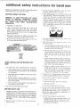
4. Read the following labels which appear on the front
of the band saw and blade guard.
c. For dusty operations,
with safety goggles
d. Use extra caution
ward workpieces.
I
O't_'aG_!_R
READ AND U_DERSTAND
I
OWNERrS
FOR YOUR OWN SAFETY:
MANUAL
BEFORE
O_TING
WHEN
SAW
INSTALMNG
with large, very small
along
o_ awk-
2. Do not feed small pieces that require
finger holding the workpiece to go under
guard area, Use jigs or fixtures to hold
work and keep yours hands away from
blade.
OR MOVING
When cutting irregularly shaped workpieces,
plan your work so it will not pinch the blade.
A piece of molding, for example, must lay flat
or be held by a fixture or jig that will not let it
twist, rock or slip while being cut.
4.
Properly
support
round material
such as
dowe! rods, or tubing. They h_ve a tendency
to roll while being cut, causing the blade to
"bite." To avoid this, always use a "V" biock,
or clamp the workpiece to a miter gauge.
THE
saw movement:
a. Bolt or clamp the saw to a sturdy level workbench
or stand where there is plenty of room for feeding
the workpiece.
b. Adjust the saw so the table is level and the saw
does r_ot rock.
c. Bolt the bench or stand to the floor if it tends to
slip, slide, or tip over during operations like cutting
long, heavy boards.
e.
suddenly
caught
in the blade:
1. Do not wear gloves.
2. Remove
all jewelry
3. Tie back
long hain
4,
g.
EACH USE
2. Plan your work to protect your eyes, hands, face,
ears and body.
To avoid risk of hearing damage, wear ear plugs
or muffs during extended periods of operation.
f. To avoid being
d. Turn saw off and unplug electric cord before moving the saw to a new area.
2. Store and use the band saw indoors.
1. Inspect your saw. If any part of this band saw is
missing, or bent, or failed in any way, or any electrical
components do not work properly, turn the saw off,
remove switch key, and unplug the saw. Replace
damaged, missing, or failed parts before using the
saw again.
your
the
the
the
3.
J
!. To avoid injury from unexpected
BEFORE
wear a face shield
1. Use extra supports (tables, saw horses, etc/
for any workpieces
large enough to tip when
not held down to the table top.
THIS M_C, FUNE:
ALLOW
TOOL TO
STOP
BEFORE
ADJUSTING
I
......
YOUR
h.
Roll long sleeves
and loose clothing.
above
the elbow.
To avoid injury from accidenta_ starting, always
unplug saw, turn switch off and remove switch
key before removing the guard, installing or removing any blade, accessory or attachment,
or
making any adjustments.
To avoid slips and jams
1. Choose the right
material and the
do, Use this band
like products and
causing
injury:
size and style blade for the
type of cutting you plan to
saw to cut only wood. woodplastic,
2, Make sure the blade teeth point downward
toward the table.
3. Make sure the blade tracking guides and
thrust bearings are properly adjusted,
4, Always Check and correctly
tension.
adjust blade
To avoid accidental blade contact, minimize blade
breakage and provide maximum blade support.
1. Always adjust the upper blade guide and blade
guard to just clear the workpiece.
2. Plan _'our hand placement so your fingers will
not be where a sudden slip could cause them
to hit the blade.
Make sure all clamps and knobs are tight and
there is no excessive play in any parts,
k. To avoid an electrical shock, make sure your fingers do not touch the metal prongs on the plug
when installing or removing the plug to or from
a live outlet.
Never turn your band saw "ON" before clearing
everything except the workpiece and related feed
or support devices off the table.
WHENEVER
SAW IS RUNNING
WARNING: DO NOT ALLOW FAMILIARITY (GAINED
FROM FREQUENT USE OF YOUR BAND SAW) TO
CAUSE A CARELESS MISTAKE. ALWAYS REMEMBER THAT A CARELESS FRACTION OF A SECOND IS SUFFICIENT TO iNFLICT SEVERE INJURY.
a. If your saw makes an unfamiliar noise or if it
vibrates excessively, stop immediately. Turn the
saw off. Remove switch key and unplug the saw,
Do not restart until finding and correcting the
problem.
b. Avoid awkward hand positions where a sudden
slip could cause a hand to move into the blade.
c. Feed the workpiece only fast enough to let the
blade cut without bogging down or binding.
d. Before freeing jammed material, turn saw off. Remove switch key. Remove plug from power
source outlet. Wait for all moving parts to stop.
e. When backing up the workpiece, the blade may
bind in the kerf (cut). This is usually caused by
sawdust clogging up the kerr or because the
blade comes out of the guides. If this happens:
1. Turn saw off.
2. Unpiug saw.
3. Remove switch key.
4. Wait for all moving parts to stop.
5. Remove band saw cover.
6. Stick a flat blade screwdriver or wedge into
the kerf.
7. Turn the upper wheel by hand using your palm
while backing up the workpiece.
f. Before removing loose pieces from the table, turn
saw off and wait for all moving parts to stop.
g- To avoid injury from untested or improper accessories, use only Recommended Accessories
listed on the Accessory page of this manual.
glossary of terms for woodworking
Beveling
An angle cutting operation through the face of the board.
Crosscut
A cutting operation made across the width of the
workpiece.
Compound Cutting
A simultaneous bevel and miter cutting operation.
FPM
Feet per minute_ Used in reference to surface speed
of blade.
Freehand (as used for band saw)
Performing a cut without the workpiece properly supported on the work table.
Gum
A sticky, sap-based residue from wood products.
Kerf
The material removed by the blade in a through cut or
the slot produced by the blade in a non-through or
partial cut,
Leading End
The end of the workpiece which is pushed into the
cutting tool first.
Mitering
An angle cutting operation made across the width of
the workpiece.
Push Stick
A device used to feed the workpiece through the saw
during narrow ripping type operations so the operator's
hands are kept well away from the blade,
Resaw
A cutting operation to reduce the thickness of the workpiece to make thinner pieces.
Resin
A sticky, sap-based substance that has dried.
Ripping
A cutting operation along the length of the workpiece.
Sawblade Path
The area of the worktable or workpiece directly in line
with the saw blade.
Set
The distance the tip of the saw blade tooth is bent
outward from the face of the blade.
Trailing End
The workpiece end last cut by the saw blade.
Workpiece
The item on which the cutting operation is being performed, The surfaces of a workpiece are commonly
referred to as faces, ends, and edges.
Worktable
The surface on which the workpiece rests while performing a cutting operation.
electrical
motor specifications
requirements
This machine is designed to use, and is equipped with, a 172=3RPM motor. It is wired for operation on 110-120 volts, 60 Hz., aJternating current.
(TOOL MUST NOT BE CONVERTED TO OPERATE ON 230 VOLT).
For replacement
manual.
motor
refer to parts list
in this
CONNECTING TO POWER SUPPLY OUTLET
This machine must be grounded while in use to
protect the operator from electric shock.
Plug power cord into a 110-120V properly grounded type outlet protected by a 15-amp. fuse or circult breaker.
tf you are not sure that your outlet is properly
grounded, have it checked by a qualified electrician.
WARNING:
DO NOT PERMIT
FtNGERS
TO
TOUCH THE TERMINALS
OF PLUGS WHEN
iNSTALLiNG OR REMOVING THE PLUG TO OR
FROM THE OUTLET.
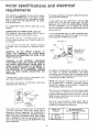
This plug requires a mating
ed type outlet as shown.
if power cord is worn or cut, or damaged
way, have it replaced immediately.
Your unit is for use on 110-120 volts,
plug that looks like below.
in any
and has a
GROUNDING
PRONG
PROPERLY
GROUNDED
3 PRONGOUTLET
This power tool is equipped with a 3-conductor
cord and grounding
type plug which
has a
grounding
prong, approved
by Underwriters'
Laboratories and the Canadian Standards Associatf,on. The ground conductor
has a green jacket
and is attached to the tool housing at one end
and to the ground prong in the attachment
plug
at the other end.
ground-
If the outlet
you are planning to use for this
power tool is of the two prong type, DO NOT
REMOVE OR ALTER THE GROUNDING
PRONG
IN ANY MANNER.
Use an adapter as shown
below and always connect the grounding lug to a
known ground.
It is recommended
that you have a qualified electrician replace the TWO prong outlet with a properly grounded THREE prong outlet.
GROUNDINGLUG
SCREW
PLUG
7/J...j.._
WARNING:
tF NOT PROPERLY
GROUNDED
THiS POWER TOOL CAN CAUSE AN ELECTRICAL SHOCK PARTICULARLY
WHEN USED IN
DAMP LOCATIONS
CLOSE TO PLUMBING.
iF
AN ELECTRICAL
SHOCK OCCURS THERE iS
THE POTENTIAL
OF A SECONDARY
HAZARD
SUCH AS YOUR HANDS CONTACTING
THE
SAW BLADE.
3-conductor
\
I _L _
CONNECTEDTOA
_
_. 2-PRONG
RECEPTACLE
ADAPTER
An adapter as illustrated is available for connecting plugs to 2-prong receptacles.
The green
grounding
lug extending from the adapter must
be connected
to a permanent ground such as to
a properly grounded outlet box.
NOTE: The adapter illustrated
is for use only if
you already have a properly grounded
2-prong
receptacle.
Adapter is not allowed in Canada by
the Canadian Electrical Code.
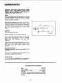
The use of any extension cord will cause some
loss of power. To keep this to a minimum and to
prevent overheating
and motor burn-out, use the
table below to determine the minimum wire size
(A.W.G.) extension cord.
Use only 3 wire extension
cords which have 3prong grounding
type plugs and 3-prong receptacles which accept the tools plug.
Lenglh of the
Conductor
Wire Sizes Required
(American Wire Gage Number)
120V Lines
O +25 Feet
26- 100 Feet
Over 100 Feet
No. 14
No. t2
No. 8
contents
CONTENTS
POWER
TOOL
WARRANTY
....................
GENERAL
SAFETY INSTRUCTIONS
POWER TOOLS ..............................
ADDIT!ONAL
FOR BAND
2
FOR
2
SAFETY iNSTRUCTiONS
SAW .............................
3
MOTOR SPECiFiCATIONS
AND ELECTRICAL
REQUIREMENTS
.............................
UNPACKING
AND CHECKING
CONTENTS
5
.....
6
ASSEMBLY
Mounting
Band Saw to Workbench .............
Clamping
Band Saw to Workbench
............
InstalJing the Table ...........................
installing
the Blade ..........................
Tensioning
the Blade ........................
Tracking the Btade ..........................
Adjusting
the Table Square to 8tade .........
Adjusting
Upper Blade Guide
Assembty ..................................
Adjusting
Upper Blade Guides ...............
Adjusting
Upper Thrust Bearir_g .............
Adjusting
Lower Blade Guide
Assembly
..................................
unpacking
TOOLS
7
8
8
9
10
11
!t
12
12
12
GETTING
TO KNOW YOUR BAND SAW
Tension
Adjustment
Knob ...................
Cover Knobs ................................
Blade Guides
...............................
Tension Lock Knob .........................
Guide 8at Lock Knob .......................
Table Lock Knobs ...........................
Bevel Scale .................................
On.Off Switch
..............................
BASIC BAND SAW OPERATION
Sawing ....................................
MAINTENANCE
..............................
Lubrication
.................................
RECOMMENDED
ACCESSORIES
TROUBLESHOOTING
REPAIR
PARTS
t2
13
13
14
14
14
14
14
14
14
14
15
16
!6
.............
........................
..............................
16
17
18
t2
and checking
NEEDED
Adjusting
Lower Blade Guides ...............
Drive Belt Tension
..........................
Adjusting
Table .............................
contents
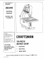
WARNING:
FOR YOUR OWN
SAFETY,
NEVER
CONNECT
PLUG TO POWER SOURCE
OUTLET
UNTIL ALL ASSEMBLY
STEPS ARE COMPLETE,
AND YOU HAVE READ AND UNDERSTAND
THE
SAFETY AND OPERATIONAL
iNSTRUCTiONS.
Model 113.244513 Band Saw is shipped
in one carton,
complete
Separate
all parts
from
packing
materials
and
check
each item with illustration
and "Table
of
Loose Parts".
Make certain
all items are accounted for, before discarding
any packing
material.
! ;_ P,C!_W;_[NCH
16 & 316
CO,VBP,AqON SOLARE MUST 8E TRUE
WARNING:
IF ANY PARTS ARE MISSING, DO NOT
TRY TO ASSEMBLE
THE BAND SAW, PLUG IN THE
POWER CORD, OR TURN THE SWITCH ON UNTIL
THE M_SSING PARTS ARE OBTAINED
AND INSTALLED CORRECTLY.
TAOL_____EE
OZ
LApTs
.............
BaSiC saw assembly
................
-_-lr_
Owners Manual
....................
Saw Table assembly
...............
Bag Assembh,' Pa[t #69181
Co_:_taining the fodowing
parts:
Switch,
Key ........................
t
• ii
......
-O
1
1
I
1
1
I
I
I
t
!
I
!
l
I
1
I
I
|
Nut, Wing !/4-20 ................
Screw, Truss Hd. !420×
3/4 .........
t
1
f
t
_,_asher
7_64
x ;_:_8 × 1,16
..........
Wrench,
Hex L"
1_8
Wrench,
He× 'L" 3/16 ...............
Washe_ 17,'64 :< 47,64 x 1/16 .........
b_,_catc r, Be',' .....................
Screw. Pan Cross 10-24 x !/4 .....
Insert, Table
Knob ..............................
•
I
I
!
2
!
!
"
2
m ........
assembmy
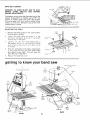
MOUNTING
BAND SAW TO WORKBENCH
If band saw is to be used ;q a p_,r ,,_.r,_,,_t !ocation, it should
be fastened
securely
to a firm supporting
surface such as a workbench
NOTE:
inse,qec
top
Front
from
two
mounting
the boitom
with
bolts
washer
should
be
aed nul ,,_n
tf mounting
to a workbench,
holes
should
be
drilled
through
supporting
surface
of the workbench using dimensions
illustrated.
I
Each leg should
be bolted
securely
using
5/16" diameter
machine
screws_ Iockwashers,
and
'*< (not
•5/16. _' hex
.
m_,.,
included).
Screw
iength shouid
be 1u:_ _ _.s J_,e thickness
of
the bench top.
2
Locate and mark
to be mounted.
3.
Drill
4) 318"
bench.
4.
Place band
m feet with
5,
Insert
the hoies
diameter
where
holes
band
through
saw on workbench
aligning
holes drilled
in workbench.
all four
5/16"
screws
i+-
j 4,-
saw is
work-
0 _3,'_6"--_
i
holes
and tighten.
An alternate
method
of mounting
is to fasten
band saw to a mounting
board. The board should
be of sufficient
size to avoid tipping
of saw while
in use. Any good grade of plywood
or chipboard
with a 3/4" minimum
thickness
is recommended.
(Thinner chipboard
can break.)
Follow
instructions
for mounting
to work-bench_ substituting
a board
18" x 24" minimum
size and using
5i16 inch
flat
head
screws,
iockwashers,
and hex nuts (not included).
Screw
length
should
be 1_,,_2" plus
the thickness
of the mounting
board.
NOTE: For proper
stability,
holes must be
counter sunk so screw heads are flush with the
bottom surface of supporting board.
_'•
24'
Mit';
.................................................................................
-_
÷q
assembly
2.
Securely
clamp board
"C" clamps.
to workbench
using
"C"
CLAMP
NOTE: Supporting surface where band saw is
mounted
should be examined carefully
after
mounting to insure that no movement during use
can result. If any tipping or walking is noted,
secure workbench or supporting surface before
operating band saw.
CLAMPING
BASE
BANDSAW TO WORKBENCH
The Band Saw can be clamped directly
to a
workbench using two (2) or more "C" clamps on
base of unit.
WORKBENCH
GUIDE BAR
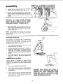
iNSTALLING THE TABLE
Apply a coat of automobile wax to the table top
and inside surfaces of trunnion
that slide on
frame.
1.
,
.
UPPER
GUIDE
ASSEMBLY
Loosen the guide bar lock knob and positior
the upper guide assembly all of the way up.
Tighten lock knob.
Locate two _2) knobs and two (;2) 17/64 x
47/64 x 1t16 washers in loose parts bag, and
the table assembly in loose parts.
TABLE
ASSEMBLY
Place table assembly onto band saw frame
with the trunnion
against mounting
rib in
frame.
"BAND SAW--..--FRAME
MOUNTING
BIB
TRUN
TRUNNION
SLOTS
4.
Hold table assembly against the frame and
install two (2) table lock knobs and washers
as shown through
the trunnion
slots and
tighten.
TABLE LOCK
KNOBS
BANDSAW
FRAME
5.
Locate bevel indicator
and 10.24x1/4
cross hd. screw in loose parts bag.
6.
Install bevel indicator
and screw
using a phillips screwdriver.
pan
as shown
NOTE: This unit comes with the Band Saw blade
installed, assembly continues on p. 10, "Tensioning the Blade."
t
REPLACING THE BLADE
|
t
\
I_
GU,OEBAR
_
BLADEGUARD
1.
LOCK KNOB
UPPERGUIDE
Loosen the guide bar lock knob and position
the upper guide assembly approximately
one
inch above the table and tighten lock knob.
,
Loosen the two blade guard mounting
and remove the blade guard.
screws
T
,
,
Loosen the guide bar lock knob and position
the upper guide assembly approximately
two
inches above the table as shown and tighten
the lock knob.
GUIDEBAR
LOCK
UPPER GUIDE
ASSEMBLY
Remove table insert, truss head screw, washer and wing nut from the table (See Assembly, p. 13 - "Adjusting
the Table"). Replace
these parts after the blade is installed, tensioned and tracked.
5.
Loosen the two screws in the front of the
upper blade guide assembly that secure the
blade guides and separate them about 1/8".
6.
Loosen the two screws in the side of the
upper guide assembly and slide guides and
thrust bearing all of the way back.
7.
Tighten all screws.
I COVER
KNOB
8.
COVER
Loosen the three (3) cover knobs by turning
counterclockwise
and remove cover.
NOTE: Replace the bandsaw cover after blade is
properly installed, tensioned and tracked.
"--d-
KNOB
9
t FRAME
assembly
(3. Loosen the two screws that secure the lower
blade guides and separate them about 1t8".
!0.
Loosen
the screw holding
the
guide support
and slide support
toward the rear of the saw, and
screws,
lower
blade
all the way
retighten
a|l
[
\
i
WARNING:
TO
AVOID
BEING
SCRAPED
SHOULD
BLADE
SUDDENLY
UNCOIL,
WEAR
SAFETY
GOGGLES
AND CAREFULLY
UNCOIL
THE BLADE HOLDING
IT AT ARMS LENGTH.
11. Place the blade
over the wheels
with
the
teeth pointing
downward
toward
the table as
showrr.
Make sure the blade =s in the center
ot the rubber tires.
NOTE: Your bandsaw
blades.
56-7f8 inches
with this Saw,
TENSIONING
can use only 114 inch wide
Ion_q. A blade is included
TEr'_S]ON
AOjUST/t4G
Kt,;O_
THE BLADE
The bandsaw
is equipped
with a self-limiting
tensiorr
device.
The tension
is factory
set and
should
not need adjustment,
The btade must be
installed
before tension
can be set.
1,
Turn
tension
adjustment
knob
contacts
washer and sleeve,
2,
DO NOT turn
resistance
if
setting for a
cause starting
until
knob
/
failure.
To release
wise
until
sleeve,
3,
COMPENSATION
knob after contact
is made and
felt.This
is the proper tension
1/4"
blade,
Overtightening
may
problems
and cause early bearing
//_
TENSION SCRE\
tension
turn knob counterclockknob
is above
the washer
and
FOR WEAR
Tension screw is provided
to make minimal
adjustments
due to wear. The tension screw
creates a drag between the wheel guide and the
frame,
1.
.
Remove
the blade
before
adjusting.
Use a phillips screw driver to adjust the tension screw, Turn clockwise
to increase the
drag (tension).
WARNING: OVER TENSION AND FAILURE TO
PROPERLY SET BLADE GUIDES AND THRUST
BEARING WILL CAUSE PREMATURE
BLADE
BREAKAGE.
FOLLOW
ADJUSTING
BLADE
GUIDE ASSEMBLIES COMPLETELY
TO HELP
MAiNTAiN NORMAL BLADE LIFE.
Check tension by {iffing up on tension knob, if the
tension knob will not move the tension screw iStOO
tight. Adjust
by turning
tension
screw
counterclockwise
and recheck.
10
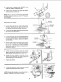
TRACKING THE BLADE
Tension
b{ade,
!.
knob must be t ghtened
before
tracking
T(:';SOft
"_'
_,u\,
5Er SCRF
;'-,
_ KNOB
Turn the upper
wheel
by hand (clockwise)
and check if the btade remains
in the approximate center of the tires. If the blade moves
away from the center
of the tires, while you
are turning
the wheels, adjust as follows:
Turn
the
tracking
adjustment
set
screw
sNght!y
with
a !18" hex wrench
(Turning
the set screw moves the tension
wheel back
and forthj
A,
B•
if the blade
band saw:
moves
toward
the
front
of
"?
the
Turn the tracking
adjustment
screw ctocM
wise about
114 of a turn, as though
you
were tightening
it.
If the blade
band saw:
moves
toward
the
back
blade to ru,'_ in the approximale
all tires.
of the
C,
Turn
the
tracking
adjustment
counterclockwise
about
114 of
though you were !oosening
it.
Turn
ALIGNING
the screw
THE TABLE
1
t.oo__ef
2
Place a sqcare on
biade as illustrated
3
T
ock
l, ¸ ,J table
up or
(__jqr_;e,_ to b}ade
. g]
4,
table
_;
lock
just
enough
SQUARE
screw
a turn as
to cause
the
TO BLADE
the
table
__.
.._...___.___]__,]in fiGht
of
the
.
down
to al_gn
table
90
iO degree
position)
and
_'"
KNOBS
_-: .................
[_i_ _
!
!
©
k "_'"
, >
€,t
Adlu.>,
zero stop set screw
using a 1i8 > hex
wrenct_
tJntU set screw
just iouches
frame.
5,
Check
squareness
of blade
readiustments
if necessary
6
Set
bev(_,i
r:dd;ator
to
to
!_r;e up .,.qt_
table
©
Make
Zero
ZERO STOP
NOTE: When table is tilted
to a bevel angle, the
lower blade guide support
should
be lowered
to
clear the table. After bevel cutting
and returning
table to zero position,
always
raise
the lower
blade guide
up to provide
maximum
support
for
the blade.
LOWER
GUD r- SUPPORT
11
of
After
adjusting,
turn upper
wheel
by b,and
clockwise
a few turns
and notice
if the
blade remains
in the approximate
center
of
the tires• readjust
if necessary,
until
blade
is tracking
properly.
...... B,_.
........ ._
knob. "<,
center
NOTE:The
upper and tower blade guides support
the blade and keep it _from twisting during operation. An adjustment is necessary when blades
are changed, reptaced or |nstaited for the first
ttme.
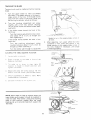
ADJUSTING UPPER BLADE GUIDE ASSEMBLY
1.
Loosen lower screw
on side of upper blade
guide
assembiy
and slide assembly
forward
unht the front edge of the blade guides
are
approximately
1/32" from the GULLET ot the
saw blade, Tighten
screw.
_ULL_:!
!!l
ADJUSTING
UPPER
BLADE
GU IDES
Loosen the lwo screws
that Iock the upper
blade guides and press the two guides
even=y
against
the sides
of the blade
but do not
pinch the blade, Release
the guides
and rotate the upper wheel slightly
clockwise
moving the btade
downward.
Make
sure
one
guide is not further away from the blade than
the other. Tighten
both screws.
ADJUSTING
UPPER
THRUST
I
_
BLADE GUllIES
BEARING
NOTE:
The thrust
bearing
supports
the btade
from the rear and will rotate when the blade is
pushed against
it while you are cutting_
As soon
as you stop cutting,
the bearing
should
stop
rotating
To adjust,
loosen the upper screw on the side
of the upper blade guide assembly
and slide
the bearing
forward
until it is approximately
1/32"
from the back
of the b_ade. Tighten
screw. Rotate
upper wheel slightly
clockwise
to check clearance.
Readjust
ii necessary,
ADJUSTING
LOWER BLADE GUIDE ASSEMBLY
Loosen the screw (as shown)
on the side of
the lower
blade
guide
assembly
and slide
assembly
forward
until
beanng
as approxP
matety
tf32"
from
the back of the blade.
Blade guides
will align with this adjuslment.
Tighten
screw.
i
ADJUSTING
,
LOWER
BLADE
GUIDES
Loosen the two screws that lock the lower
blade guides and press the two guides evenly
against the sides of the blade but do not
pinch the blade. Release the guides and rotate the upper wheel slightly clockwise moving the blade downward,
Make sure one
guide is not further away from the blade than
the other, Tighten both screws.
NOTE: After all adjustments have been made,
turn the upper wheel by hand (clockwise)
a few
turns to check blade travel and clearance.
:..-I--IBLADE
BLADE
GUIDES
12
DRBVE BELT TENSION
/Io/
;O
r
WARNING: TO AVOID iNJURY DUE TO ACCiDENTAL
START,
UNPLUG
TOOL
BEFORE
MAKING ADJUSTMENTS.
The tension on the drive belt has been set at the
factory, if adjustment
is needed, use a 3;16" hex
wrench to loosen upper and lower cap screws,
Pult motor away from drive wheel to apply proper
tension to drive bett. Retighten cap screw while
holding motor in place
ADJUSTING
THE TABLE
1.
Replace the blade guard
bly and tighten
screws_
2.
Locate
the table insert
and piace
it in the
opening
in the table. A!gn
slot in the insert
with the s_ot in the tabte.
.
on the upper
assem-
Locate a I/4 - 20 x 314" truss head screw, a
ftat washer,
and a 1/4 - 20 wing nut in loose
parts_ Insert screw
into hole in tab!e top as
illustrated
4.
From the underside
of the table, install washer and wing nut onto the truss head screw
and tighten
finger
tight.
This will keep the
table flat and in alignment.
5,
Replace
the band
saw cover,
erring to know your band saw
2
COVER
KNOBS
3
BLADE
,U_DES
TABLE
6
LOCK
KNOBS
TRUNN!0N
BACK
FRONT
13
7
BEVEL
SCALE
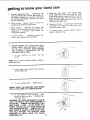
getting to know your
!+
Tension
adjusting
knob...T_ghtening
the
knob (c_ockw_se)'wiII
incresse the tension on
the blade. Loosening
it {counter clockwise)
will decrease
the tension,
(Tension lock knob
must be re}eased},
2,
Cover knobs
,. Secure cover to
tightening all three (3) cover knobs.
3.
frame
B_ade Guides
. Supports
the btade
keeps il from tw+st_ng during
operation.
adjustment
_s necessary
when
blades
changed
or replaced,
4
Tens|on
screw
..
tween upper wheel
i
/
and
An
are
maintains
tension
guide and frame.
ii
'
ii
•
by
and saw
5. Guide bar lock knob...The
upper blade
guide assembly should just clear the workp+ece while cutting. Atways adjust the upper
guide assembly and lock the guide bar by
tightening the blade guide lock knob before
turning on the band saw.
6. Table lock knobs +.. Loosening knobs allows
the table to be tilted and tightening
knobs
locks the table in place.
7. Tilt (bevel) scale...
Shows
tilted for bevel cutting.
degree
be-
i
iJ
n
=
ii
--
ON-OFF
SWITCH.
The On-Off
SwitCh
has a
locking
feature,
THIS FEATURE
IS iNTENDED TO HELP
PREVENT
UNAUTHORIZED
AND
POSSIBLY
HAZARDOUS
USE
BY
CHILDREN
AND OTHERS.
1
To turn
switch
mach+ne
NOTE: Key +s made
loose parts bag.
on
of yellow
insert
plastic:
key
into
locate
in
=_
Insert finger under
end Of switch out.
,i
Switch lever and _)ull
ii rll
3
To turn machine
OFF.
PUSH lever in.
NEVER LEAVE THE MACHINE UNATTENDED
UNTIL IT HAS COME TO A COMPLETE STOP.
4.
table
To lOck switch in OFF position+.,hold
switch IN with one hand...
REMOVE key
with other hand,
WARNING: FOR YOUR OWN SAFETY, ALWAYS
LOCK THE SWITCH "OFF" WHEN MACHINE IS
NOT 1N USE...
REMOVE KEY AND KEEP IT IN A
SAFE PLACE...
ALSO...IN
THE EVENT OF A
POWER FAILURE (ALL OF YOUR LIGHTS GO
OUT) TURN SWITCH OFF ... REMOVE THE KEY
AND STORE trT REMOTE FROM BAND SAW.
THSS WiLL PREVENT THE MACHINE
FROM
STARTING
UP AGAIN
WHEN
THE POWER
COMES BACK ON.
14
,i
__
,-J--=_,_,_--=,
is
basic band saw operation
A ba_sd saw is basica}_y a 'curve
cutting"
n,,a< hme. _t is aso used _o; straight-line
ct fling opera
t_oes suct_ as c_oss cutting
ripping,
mitering,
beveling
compound
clotting,
and resawmg
it s
rot capabte of do _g inside cutting
This band
saw is designed
wood like products
only.
to
cut
wood
and
For generaI type scroll c,4tting, fo!low the pattern
lines by pusIing
arid turning
the workpiece
at
the same time. Do not try to turn the workpiece
while engaged
m the blade without
pushing
it;
the workp_ece
couid bind or twist the b_ade
_',_,;rL :_N2,'4_
RIGHT
- Pb_rmm, q. ,-._head by turr'!rlg
for cutting
a curve
A curve cut is best performed
by keeping
the
pattern
line in line with the blade while turning
_t_e workpiece
before
the radius of the curve is
cut. The b!ade should
cut i_ the middle
of the
pattern
!ine (saw kerf) since wood cutting
band
saw biades are thin
NOTE: Blade g,.iard is ,_a_sed and right hand
for clarity of picture on_y.
_:xx[?!;
,v'. r_,'....,.,',
removed
PAT ?E R'_i t i'_iE
WRONG
- Not
curve could
bind
forced.
WARNING:
ADJUST THE UPPER GUIDE
BLY TO JUST CLEAR THE WORKPIECE.
ASSEM-
1. Use both hands while feeding the work into the
blade. Hold the workpiece firmly against the table.
Use gentle pressure. Do not force the work, but
allow the b_ade to cut.
2
The smaJJest diameter circle that can be cut out is
determined
by the width of the blade. A I/4" wide
blade will cut a minimum diameter of approximately
I-1/2".
Relief cuts are made when an intricate
curve (too
small a radius for a 1/4dnch b_ade) iS to be cut. A
relief cut }s made by Cutting
through
scrap section Of workpiece
to curve in pattern
line. then
carefully
backing
blade out. Several
relief
cuts
should
be made for intricate
curves,
then follow
pattern
line as sections
are cut off
of curve
"relieving"
blade pressure.
NOTE: Biade guard is raised
for ciarity of picture oniy.
and right hand
removed
15
planning
or twist
ahead
for cutting
blade if workp_ece
a
_S
maintenance
WARNING:
FOR YOUR OWN SAFETY, TURN
SWITCH
"OFF"
AND REMOVE
PLUG FROM
POWER OUTLET BEFORE MAINTAINING
OR
LUBRICATING YOUR BAND SAW.
TIRES
Pitch and sawdust that accumulate on the tires
should be removed with a stiff brush or scraped
off with a piece of wood. Do not use a sharp
knife or any kind of solvent.
When the tires become worn they should be replaced. When replacing the tires, put a thin layer
of rubber cement on the outside of the wheels
and inside of the tires. Allow to dry, then slide
tires onto wheels aligning
tires inside wheel
edges.
BLACK
GENERAL
Keep you r Band Saw olean.
G_EEN
MOTOR
Remove sawdust from the inside frequently.
Do not allow pitch to accumulate on the table,
blade insert, blade guides, or thrust bearings.
Clean them with Craftsman
Gum and Pitch
Remover.
Apply a thin coat of automobile-type
wax to the
table so the wood slides easily while cutting.
Also apply wax to the inside surfaces
of the
trunnion.
MOTORIELECTRICAL
Frequently vacuum or blow out any sawdust from
the motor.
If the power cord is worn, cut, or damaged
way, have it replaced immediately.
in any
LUBRICATION
All of the BALL BEARINGS
are permanently
Lubricated. They require no further lubrication.
RECOMMENDED
ACCESSORIES
Item
Cat. No.
Miter Gauge ............................
9-24214
Blades (56-7/8" length) ..............
See Catalog
Leg Set .................................
922244
The above recommended accessories are current
and were available at the time this manual was
;)rinted.
16
troubleshootin
_RNING:
FOR YOUR OWN SAFETY, TURN
SWITCH
"OFF"
AND REMOVE PLUG FROM
POWER OUTLET BEFORE READJUSTING
OR
ALIGNING YOUR BAND SAW.
TROUBLE
Motor will not run.
Blade does not run in the
approximate center of the
upper wheel.
Band Saw slows down
when cutting.
-_.ades breaking.
PROBABLE CAUSE
REMEDY
1. Defective On-Off switch.
1.
Defective power or motor cord.
before
using
!2, Consult Sears Service. Any
attempt to repair
this motor may create a HAZARD
unless
repair is done by a qualified
service technician_ Repair service is available
at your nearest Sears Stere.
1. Not tracking properly_
1. Adjust tracking, see Assembly
"Tracking the Blade."
Cutting
t.
too small a radius,
1. Stop feeding, and back up
slightly, until the band saw
2. Replace blade.
2. Dull blade.
1. Too much tension.
,
Too much blade tension.
.
Blade guides and bearings
not properly adjusted.
2. Defective
Section,
the material
speeds up.
1, Adjust tension. See Assembly
"Tensioning
The Blade."
2. Use correct cutting technique.
Band Saw Operation Sect ion.
section
See Basic
1. Adjust blade tension. See Assembly
section "Tensioning
The Blade."
2. Adjust belt tension. See Assembly
Section
"Drive Belt Tension."
2. Too much belt tension.
Blade will not allow for
general straight cutting.
parts
2. Motor Defective,
2. Kink in blade caused by cutting too small a radius or turning the material too fast when
cutting.
Motor sounds under
load when not cutting.
Replace defective
Band Saw again.
1,
Adjust upper and lower blade
guides and
bearings. See Assembly
section
"Adjusting
Upper Blade Guide Assembly"
2. Replace blade.
blade.
17
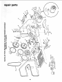
repair parts
\
\
\
\
\
\
rr
_
z _
_u z
_0._
€(
18
X
_
x
x
X£O
0
_-
_
"::
x__
C
0
O.
"_.
m.
oo
£'_x_
_c_
z:._.
__
m
mA _
@3
Q
@0
_ec--'6
Q
Z
.... o
o
.......
i
_
m
_
0
0
E
tO
m
m
0
0
"0
0
w
N
0
C_
..Q
0
"r,_
d
0
"0
Z
W
05
r_
>m
I---
0
Z
I
0
Z
o
0
J
0
¢0
0
LI.
nO
O9
t..O
_
121
,i
Z
0
¢0
O
r-'--
x
_m
__
_
x c°-.
f._-
0003
x
_
"-'x
-_ ._..
r_
,_i"
o
C?
Or-
_--
.£
Q.
'<:P _"_
0
._
LO
,
_-ggo
,n
m o:=,_- 0
>ffl
rr
t.u
_
oOo9 u_
oo
.JZ
-J
_o
_
_
0
O_
W_O
_ _ 00 0 x- r.o
0
_
,._o
I
t-
m_m_N_mm_mmm
_mmN
_
0
19
n
I
0
NN
N
I
_
_'_
_0__
<
_
o9
E_
I
i
0
03
ooo_=_g
z+
-
0
_ , , _ ,
o!
nO
cO
m
>
13_o 00 __ o_
rr
x
o
eu
o
ffl
b-
_--
tO
x
W
09
_'x
x
o
o9
CH
ND SAW
SERVICE
Now that you have purchased
your 10-inch
Band
Saw should a need ever exist for repair parts
or
service, simply
contact
any Sears Service Center
and most Sears, Roebuck
and Co. stores.
Be sure
to provide
all pertinent
facts when you call
or
visit.
The model number
of your 10-inch Band Saw will
be found on a plate at the right-hand
side of the
saw.
HOW TO ORDER
REPAIR PARTS
WHEN
ORDERING
REPAIR
PARTS,
GIVE THE FOLLOWING
INFORMATION:
PART NUMBER
PART
DESCRIPTION
NAME
10-Inch
MODEL NUMBER
113.244513
ALWAYS
OF ITEM
Band Saw
All parts listed
may be ordered
from any Sears
Service
Center
and most
Sears stores.
_f the
parts
you need
are not stocked
locally,
your
order will be electronically
transmitted
to a Sears
Repair Parts Distribution
Center for handling.
Sold by SEARS,
Part No. SP5100
ROEBUCK
AND
"
CO., Ch_cag
Form No. Sp5100-!
O
, IL. 60684
U.S.A.
Pr{nted
in Taiwan.
4;89