1
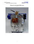
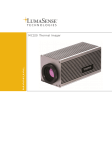
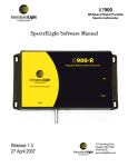
LumaSpec 800 User Manual
Worldwide distribution
VERSION 05162013
Prior Scientific, Ltd
Cambridge, UK
Prior Scientific, Inc
Rockland, MA. USA
Prior Scientific, GmbH
Jena, Germany
Prior Scientific KK
Tokyo, Japan
T. +44 (0) 1223 881711
E. [email protected]
T. +1 781-878-8442
E. [email protected]
T. +49 (0) 3641 675 650
E. [email protected]
T. +81-3-5652-8831
E. [email protected]
Visit Prior on the web at
prior.com
TABLE OF CONTENTS
PAGE
Section 1
Safety Information
Section 3
Product Features
3
Software Installation
5
Section 2
Section 4
Section 5
Section 6
Product Overview
Getting Started
1
2
4
Hardware Installation
11
Section 7
Initial Use of LumaSpec Software
16
Section 9
Setting Ranges 1 through 10
20
6.1
6.2
6.3
Connecting Fiber Optic Cable
Connecting USB Cable
Setting up the Illumination Target
Section 8
Section 10
LumaSpec Display Screen
Tools
10.1
10.2
10.3
10.4
10.5
10.6
10.7
10.8
10.9
10.10
10.11
10.12
Scans to Average
Default Wavelength
Data Collection Settings
Use Initial Dark Spectrum
Open Settings
Save Settings
Connect
Save Dark Spectrum
Export to Excel
Import Spectrum from Excel
Data Collection Start
Change Integration Time
11.1
11.2
11.3
Scale Graph to Fill Window
Transmission Mode
Absolute Irradiance Measurement Mode
18
22
Section 11
Graph Functions
30
Section 12
Troubleshooting
33
Section 13
Returns and Repairs
37
Page 1
Section 1
SAFETY INFORMATION
SAFETY WARNINGS
Always observe the following safety precautions:
• The LumaSpec 800 is powered via its USB connection. DO NOT attempt to connect the LumaSpec 800 to
a power outlet.
• This equipment is for use in moderate climates only. NEVER use the equipment in damp or wet conditions.
• Avoid excessive heat, humidity, dust & vibration.
• Do not use where the equipment may be subjected to dripping or splashing liquids.
• This equipment contains no user-serviceable parts. Refer all repairs to qualified service personnel.
• It is the user/operators responsibility to ensure good laboratory practices are followed.
Section 2
PRODUCT OVERVIEW
Page 2
The LumaSpec Model LS800S is a compact visible light spectrometer which provides quantitative spectral
power data (microwatts per square centimeter per nanometer) for microscope/optical system illumination
systems. The LumaSpec has a range of 350-800 nanometers and a resolution of 1.5 nanometers.
In Irradiance Mode
, the information for the illumination system is displayed in both a graphical and
numerical format on the LumaSpec main display. Simply clicking on the graph provides spectral power data
for the wavelength selected. Ten selectable ranges are available which allow the user to view spectral power
data at a glance for wavelength ranges of interest. Integration time is quickly changed on the main display
which allows the LumaSpec to quantify light sources from the dimmest LED to the most intense mercury
source. The user can overlay multiple saved spectrums (up to four) over the live graph to quickly compare
illumination performance over time. The LumaSpec software will save and import settings for different
illumination sources making calibrating multiple optical systems quick and easy. Collecting and saving time
stamped spectral power data is accomplished with a click of the mouse.
In Transmission Mode
, the LumaSpec software monitors and graphs 100% light output for the illumination
system and then determines the wavelength and the percent transmission for each filter placed into the light
path. This feature is extremely useful in determining the overall efficiency and remaining lifetime of optical
filter sets.
Section 3
PRODUCT FEATURES
Major features of the LumaSpec LS800S include:
• Illumination target in 3” x 1” slide format measuring spectral power at the sample plane
• 1 meter fiber optic cable
• Small footprint of 13.5 square inches
• 350-800 nanometer range
• 1.5 nanometer resolution
• Software with irradiance and transmission modes
• Graphical and numerical spectral power data
• 10 selectable ranges for spectral power at wavelengths of interest
• Time stamped spectral power data collection function
• Export and import functions
• USB powered
Page 3
Page 4
Section 4
GETTING STARTED
Identifying the Components of your System
Check to see that all the required components have been included with your LumaSpec LS800S compact
illumination spectrometer.
The standard LumaSpec 800 system consists of:
(1) - LumaSpec 800 Housing - LM407
(1) - One Meter Fiber Optic Cable - W4221
(1) - Illumination Target - LM408
(1) - USB Cable
(1) - Quick Start Guide
(1) - Software/Installation CD
LumaSpec 800 Housing
One Meter Fiber Optic Cable
Illumination Target
USB Cable
Quick Start Guide
Software/
Installation CD
Section 5
SOFTWARE INSTALLATION
Page 5
Note:
You must complete the following software installation before connection the LumaSpec 800 to your computer.
Before installing the software, please uninstall the LumaSpec software, Omni driver software and VC++ 2010
Redistributable if the software was installed previously. There is no need to uninstall .NET Framework 4.0 if
already installed on your computer.
Step 1:
Double click on the ‘Setup’ file in order to begin the installation process. A command prompt window will open
and the installation process will start.
Step 2:
Install the latest .NET Framework onto your computer. If you already have the latest .NET Framework
installed, you will see the window below. If you get this window, simply click ‘Cancel’ and then click ‘Yes’ to
confirm.
Page 6
If you do not have the latest .NET Framework installed, you will receive the following window. In this case,
you will need to proceed with the installation. In order to proceed with the installation, check the box to
agree to the Microsoft terms and conditions and click ‘Install’.
Once the installation has completed, click ‘Finish’.
Page 7
Step 3:
Install the LumaSpec software. Click ‘Next’ on the first window that opens in order to begin the installation.
On the next window, select whether you would like to install the program for all users on the computer or just
the current user by selecting ‘Everyone’ or ‘Just Me’, and then click ‘Next’. In this window, you can also
change the folder in which the program will be installed if you would like it to be a location other than the
default. Prior recommends you do not change the default location unless it is a requirement for your system.
Page 8
Click ‘Next’ in the confirmation window in order to begin the installation.
Once the installation has completed, click ‘Close’ to complete the LumaSpec software installation process.
Page 9
Step 4:
Install the drivers. The driver installation will begin automatically and install without any required action from
the user. After the driver installation has completed, the computer will need to install the ‘C++ 2010 x64
Redistributable’ as part of the driver installation (Note: If you are running a 32bit computer, the ‘C++ 2010
x86 Redistributable’ will be installed in place of the x64 version). If this program is already installed on your
computer, you will get the window below. In this situation, simply click ‘Cancel’ and then click ‘Yes’ to
confirm and the installation process will complete.
If you do not have the ‘C++ 2010 x64 Redistributable’ installed, you will receive the window below. Agree to
the Microsoft terms and conditions and click ‘Install’ to begin the installation process.
Page 10
Once the installation has completed, click ‘Finish’. The installation process is now complete and your
software is ready to use.
Page 11
Section 6
HARDWARE INSTALLATION
Connecting the Fiber Optic Cable
Connect the fiber optic cable part number W4221 to the LumaSpec Box. Connect the other end of the fiber
optic cable to the Illumination Target as show below. Tighten both connections hand tight only. Do not use
any tools when connecting the fiber optic cable.
Fiber optic cable connected to the Illumination Target.
W4221 fiber optic cable properly
connected to the LumaSpec box
and Illumination Target.
Connecting the USB Cable
Connect the micro USB connector to the LumaSpec Box and the opposite USB connector to your computer.
If you do not have the latest .NET Framework installed, you will receive the following window. In this case,
you will need to proceed with the installation. In order to proceed with the installation, check the box to
agree to the Microsoft terms and conditions and click ‘Install’.
Step 3:
Install the LumaSpec software. Click ‘Next’ on the first window that opens in order to begin the installation.
Page 12
Setting up the Illumination Target
Placing the Illumination Target aperture centrally on the optical axis of the microscope stage and at the
correct focus height is critical to obtaining repeatable spectral power readings from your illumination source.
The Illumination Target shown below has two sides, the crosshair side and the aperture side.
Aperture Side
Crosshair Side
X
4
Page 13
Setting Up the Illumination Target on a Motorized Stage
Upright Microscopes
Place the Illumination Target into the stage slide holder with the crosshair side UP. Adjust the XY stage
position until the target is located below the objective and the light from the objective falls centrally on the
crosshair target. See images below:
Objective Light is Off Center
Light is On Center of Crosshair
Use the microscope focus mechanism to focus on the crosshair inscribed on the surface of the Illumination
Target. It is recommended to start with the lowest magnification objective when trying to find and focus on
the crosshair. Note that if white light is not available the coating on the Illumination Target will allow you to
view and focus on the crosshair with many of the common fluorescent filter sets. Carefully remove the
Illumination Target and turn it over with the aperture side up. At this point the Illumination Target is ready to use.
X
Inverted Microscopes
4
Place a sample slide into the motorized stage slide holder and bring the slide into focus. Remove the sample
slide and place the Illumination Target into the stage slide holder with the crosshair side UP. Adjust the XY
stage position until the aperture is located above the objective and the light from the CONDENSER falls
centrally on the crosshair target. At this point the Illumination Target is ready to use. See images below:
Condenser Light is Off Center
Light is On Center of Crosshair
X
Setting Up the Illumination Target on a Manual Stage
Upright Microscopes - With Integrated Slide Holder
4
Page 14
Place the Illumination Target into the stage slide holder with the crosshair side UP. Adjust the XY stage position until the target is located below the objective and the light from the objective falls centrally on the
crosshair target. See images below.
Objective Light is Off Center
.
Light is On Center of Crosshair
Use the microscope focus mechanism to focus on the crosshair inscribed on the surface of the Illumination
Target. It is recommended to start with your lowest magnification objective when trying to find and focus on
the crosshair. Note that if white light is not available the coating on the Illumination Target will allow you to
view and focus on the crosshair with many of the common fluorescent filter sets. Carefully remove the
Illumination target and turn it over with the aperture side up. At this point the Illumination Target is ready to
use. Note if the manual stage moves while you are turning it from the crosshair side to the aperture side up
you will need to redo the crosshair alignment and focus adjustment.
Upright Microscopes - Without Integrated Slide Holder
X
Place the Illumination Target onto the manual stage with the aperture side UP. Adjust the position of the XY
stage until the light from the objective falls centrally on the aperture of the Illumination target. When centering
the aperture it may be helpful to minimize the spot of light coming from the objective by adjusting the aperture
stop so that the light coming from the objective is similar in size to the crosshair. Open the aperture stop
completely after alignment is finished. Raise the illumination target until the top of the target is at the focus
position. It will be necessary to move the stage slightly so that you can view and focus on the edge of the
aperture. It is highly recommended to only move one axis when looking for the edge of the aperture and to
move the stage and Illumination Target so that the light falls centrally on the aperture before taking measurements. This can be done iteratively by slowly moving the stage and maximizing the overall spectral power as
viewed on the LumaSpec software or by looking under magnification and noting two edges of the aperture
then moving the stage to the midpoint between the edges. See Images below:
Objective Light is Off Center
4
Light is On Center of Aperture
X
Inverted Microscopes – With Integrated Slide Holder
4
Page 15
Place a sample slide into the slide holder and bring the slide into focus. Remove the sample slide and place
the Illumination Target into the stage slide holder with the crosshair side UP. Adjust the XY stage position
until the aperture is located above the objective and the light from the CONDENSER falls centrally on the
crosshair target. At this point the Illumination Target is ready to use. See image below:
X
Condenser Light is Off Center
Light is On Center of Crosshair
4
Inverted Microscopes – Without Integrated Slide Holder
Place a sample slide onto the stage and bring the slide into focus. Remove the sample slide and place the
Illumination Target into the stage slide holder with the crosshair side UP. Adjust the XY stage position until
the aperture is located above the objective and the light from the CONDENSER falls centrally on the
crosshair target. At this point the Illumination Target is ready to use. See images below:
Condenser Light is Off Center
Light is On Center of Crosshair
Section 7
INITIAL USE OF LUMASPEC SOFTWARE
Page 16
Start the LumaSpec software….Start/Programs/LumaSpec
The main page for the LumaSpec program will appear and the following message will appear:
Press OK.
A message pops up that allows you to choose to automatically set integration time.
The LumaSpec software is not able to automatically set some intense illumination sources and so if this is
the first time using the LumaSpec software, click on “NO”.
Manually setting Integration Time
A window will pop up asking the user to Adjust the integration time until the maximum raw data value is
between 13,000 and 14,000 or another acceptable value (some light sources may be too dim to reach
13,000 but this would be a rare occurrence).
Page 17
Manually Setting Integration Time (Continued)
If the maximum raw data value is between 14,000 and 16,500, decrease the integration time until the value
falls between 13,000 and 14,000. Please note that the minimum value that can be input is 1. Decimals are
not allowed. The units of integration time can be changed from microseconds µs, to milliseconds ms, to
seconds. Decreasing the integration time will lower the maximum raw data value, increasing the integration
time will raise the maximum raw data value. If the LumaSpec sensor is saturated with too much light, the
maximum raw data value will sit at approximately 16383. The maximum raw data value is continuously
displayed in the lower data bar see below. A red warning icon will flash in the right hand side of the data bar
if the maximum raw data value exceeds 15,000.
Integration Time
Integration Time Units
Warning that maximum
raw data is too high
Maximum Raw Data
Lower Data Bar
Automatically Setting Integration Time
To set integration time with the automatic feature, click “Yes”. A window will appear:
The LumaSpec software will automatically adjust the integration time until the value falls between 13,000
and 14,000. A new window will appear:
At this point the user needs to block the light going to the spectrometer. Blocking the light can be accomplished by closing a shutter, turning off the light source or even blocking the input aperture. Please note if
you move the illumination target while blocking the light it will need to be relocated so that the light from the
objective falls centrally on the input aperture.
Unblock the light source to the LumaSpec and the LumaSpec Illumination Spectrometer and software are
ready to use.
Section 8
Overview
LUMASPEC DISPLAY SCREEN
Page 18
MAIN SCREEN
The LumaSpec software main screen provides detailed information for the illumination systems at a glance.
A graphical representation of the current illumination spectrum is provided centrally located in the main screen.
The three buttons located at the top of the graph are for rescaling the graph
forth between transmission
and irradiance
modes.
and toggling back and
To the left of the graph are 10 selectable wavelength ranges which will provide spectral power information
for user selectable wavelengths ranges of interest.
Page 19
Overview (Continued)
UPPER DATA BAR
The upper data bar has the Tools, Save Dark Spectrum, Export to Excel, Import Spectrum from Excel, Data
Collection Start, Change Integration Time and Help buttons. Information on the functionality of these button
are detailed separately.
Upper Data Bar
LOWER DATA BAR
The lower data bar displays the overall spectral power for the illumination system, the spectral power at a
single wavelength (chosen by clicking on the graph) and the maximum raw data value. Viewing the
maximum raw data value is useful when choosing the integration time for each illumination system.
Single Wavelength
Selected
Overall Spectral Power
Maximum Raw Data Value
Spectral Power at Chosen Wavelength
Section 9
SETTING RANGES 1 THROUGH 10
Page 20
Ten user defined wavelength ranges are available. Clicking on the check box in each range allows you to
view the range on the main graph. Two color coded vertical lines show at a glance the defined range. The
overall spectral power for the range selected is displayed below the range name.
User Defined
Wavelength
Range
Spectral
Range
Power
The range name can be changed by right clicking on the name and renaming.
The new name can include alphanumeric characters, but spaces are not allowed. The color of the range can
be changed by clicking on the color chip and selecting a basic color or clicking on the color pallet.
Right Click to Change Range Name
Click Here to Change Color
Setting Ranges 1 through 10 (Continued)
Page 21
The minimum and maximum ranges can be increased and decreased using the up/down arrows or by typing
numbers directly into the min/max ranges.
Use Arrows to Increase or Decrease Value
Users Can Also Type Value Directly Into Field
Section 10
TOOLS
Page 22
Clicking on the tools button allows the user to modify Data Collection Settings, increase or decrease Scans
to Average, increase or decrease the Default Wavelength (main display), open previous program settings,
save current program settings, Connect to the LumaSpec spectrometer, and Use Initial Dark Spectrum.
Scans to Average
Specifies the number of spectral acquisitions that the device accumulates before the LumaSpec program
displays a revised spectrum. The higher the value, the better the signal-to-noise ratio, but the slower the
response.
Scans to
Average Field
Page 23
Default Wavelength
Allows the user to increase the minimum wavelength or decrease the maximum wavelength customizing the
graph on the main display to show only the spectral information of interest to the user. Clicking on the apply
button allows the user to evaluate the change before closing the tools menu.
Data Collection Settings
The LumaSpec software allows the user to perform real time spectral data collection. The frequency, duration and start delay for the data collection function are adjusted in the tools menu. The acceptable range for
each parameter, frequency, duration and start delay is 0-999. Values can be input directly or increased and
decreased using the up/down arrows. Available units are in milliseconds, seconds, minutes and hours.
Page 24
Use Initial Dark Spectrum
Checking the use initial dark spectrum box eliminates the need to save a new dark spectrum (zero calibration)
each time the integration time is changed. Default state is unchecked.
Open Settings
Clicking on this button allows the user to recall previous settings for range selection, data collection settings,
scans to average. The user must have previously used save settings button.
Save Settings
Page 25
Allows the user to save current settings for range selection, data collection settings, scans to average.
These settings can be recalled for later use. See Open Settings.
Connect
Allows the LumaSpec software to connect to the LumaSpec Spectrometer. If unit is connected to the PC
upon start up, the LumaSpec software will connect automatically.
Save Dark Spectrum
Page 26
Calculates and saves a new zero calibration (Dark Spectrum) for the LumaSpec.
Export to Excel
Saves time stamped spectral power by wavelength in graphic and in numeric spreadsheet format. Also
saves integration time, scans to average, dark spectrum, overall spectral power information and spectral
power by range. See sample of saved data below.
Sample Exported File
Page 27
Import Spectrum from Excel
Overlays previously saved spectrum (See Export to Excel) over live graph. Up to four spectrums can be
overlayed simultaneously.
Imported Spectrum
Live Spectrum
Data Collection Start
Saves time stamped spectral power data for spectral ranges 1-10. Clicking Data Collection start requires the
user to select a location to save the data, then immediately begins collecting data. Pressing Data Collection
Stop will end date collection immediately.
“In Progress” will flash during the data collection process and Data Collection Complete will pop up when the
process is finished.
Page 28
Change Integration Time
Allows the user to change integration time.
The acceptable range for Integration time is 1-1000000000, with units of seconds, milliseconds or microseconds.
Range 1-1000000000
Units can be seconds, milliseconds
or microseconds
Page 29
Change Integration Time (Continued)
Higher integration times will increase the signal to noise ratio and provide more stable spectral power
information. Increasing integration time will increase the maximum raw data value. Integration time must be
decreased if maximum raw data value rises over 14,500. Integration time is ideally set to maintain the
maximum raw data value between 13,000 and 14,000. The image below is an example of a situation where
the current integration time is set too high. The red warning symbol in the lower right has appeared to
indicate a lower integration time needs to be chosen. The maximum raw data value is also greater than
14,000 which again confirms the integration time needs to be lower.
Integration Time it too high
Maximum Raw Data too high
Section 11
GRAPH FUNCTIONS
Page 30
Scale Graph to Fill Window
Scales Y axis of display to enlarge graph in display. Useful when overlaying multiple spectrums with widely
varying spectral power.
Can’t see entire spectrum
The green spectrum in the graph above is truncated. The entire green spectrum is visible in the graph below
after using the scale graph icon.
Entire spectrum visible
Page 31
Transmission Mode
Allows the user to place a filter in the light path and determine the percent transmission in the wavelengths
transmitted. Useful for checking filter transmission efficiency and remaining lifetime.
Click here to switch to
transmission mode
The graph below shows a halogen light source with a filter passing approximately 75% of the available light
between 510-555 nanometers. Note: The large amount of “noise” in the lower wavelength range is a
byproduct of the transmission calculation and indicates very low output in this range before inserting the filter.
Noise
Page 32
Absolute Irradiance Measurement Mode
Default LumaSpec operating mode. In this mode the LumaSpec measures Absolute Irradiance in
microwatts per square centimeter per nanometer.
Irradiance Units
Section 12
TROUBLESHOOTING
Page 33
If you experiencing problems while trying to run the LumaSpec software, performing a complete uninstall
and reinstall of the software may alleviate the problem you are having. Please follow the procedure below to
ensure all of the program components are uninstalled and then reinstall the software using the installation
procedure provided in the manual.
- Open your program list from the control panel.
For Windows 7: Go to the start menu and click on Control Panel. Select Programs and Features in
the control panel.
•
•
•
For Windows XP: Go to the start menu and click on Control Panel. Select Add or Remove Programs
in the control panel.
Uninstall the following programs from the list of installed programs:
LumaSpec
Microsoft .NET Framework 4 Client Profile
Microsoft Visual C++ 2010 x64 Redistributable (This program may be installed as the x86 version
depending on the operating system of your computer. If you have both the x64 and x86 version installed,
uninstall both programs.)
• OmniDriver-redistributable-win64-2.20 (This program may be installed as the win32 version depending
on the operating system of your computer.)
- Restart the computer.
- Go through the installation process using the CD provided with the spectrometer.
- Restart your computer after the installation has completed.
Page 34
Issue: The spectrum graph is not smooth, very noisy signal
Noisy Signal
Suggestion: Increase the integration time until the Maximum Raw Data Value is between 13000 and 14000
counts.
Issue: The spectrum graph is displaying 100% output only, not the proper spectrum.
Click to Return to Spectrum
Line @ 100%
Suggestion: Click on the Irradiance Icon
to change display from Transmission Mode to Irradiance Mode.
Page 35
Issue: Want to adjust the Y axis range manually.
Enter New Value to Rescale Y Axis
Suggestion: Right click on the graph and select Change Chart Y Axis Value. The AutoScale Window will pop
up and allow the user to choose a custom spectral power range.
Issue: The main display is blank or only shows a small portion of the graph.
Click Here to
See Entire Graph
Not Seeing Entire Graph
Suggestion: Click on the circles with the hyphen in the center on the left side of the graph to view the entire
spectrum graph.
Page 36
Issue: Saving a new Dark Spectrum (zero calibration) is inconvenient each time Integration Time is adjusted.
Suggestion: In the Tools menu, check “Use Initial Dark Spectrum” and the software will not require a new
Dark Spectrum every time Integration Time is changed.
Section 13
Page 37
RETURNS AND REPAIRS
Should you experience problems with your LumaSpec 800 and want to send it back for service, warranty or
otherwise, a Return Material Authorization (RMA) number must be obtained from the appropriate Prior
Scientific office before returning any equipment. For North and South America contact Prior Scientific Inc.
and for the rest of the world call Prior Scientific Instruments Limited on the telephone numbers shown below:
Worldwide Locations
Prior Scientific, Ltd
Cambridge, UK
Prior Scientific, Inc
Rockland, MA. USA
Prior Scientific, GmbH
Jena, Germany
Prior Scientific KK
Tokyo, Japan
T. +44 (0) 1223 881711
E. [email protected]
T. +1 781-878-8442
E. [email protected]
T. +49 (0) 3641 675 650
E. [email protected]
T. +81-3-5652-8831
E. [email protected]
Prior Scientific recommends having the LumaSpec 800 calibrated annually to ensure reliable and
accurate performance. Contact your local Prior Scientific office for more information.