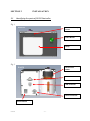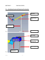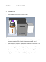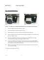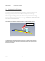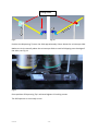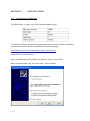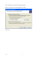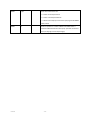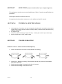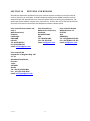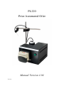
1
PL220
Prior Automated Oiler
Manual Version 1.04
PL220
Table of Contents
SECTION 1 IMPORTANT SAFETY INFORMATION
3
3
1.1 IMPORTANT SAFETY INFORMATION
SECTION 2 UNPACKING & INSPECTION
4
SECTION 3 INSTALLATION
3.1
3.2
3.3
3.4
3.4
IDENTIFYING THE PARTS OF THE PL220 CONTROLLER.
IDENTIFYING THE PARTS OF THE DISPENSING TIP ASSEMBLY.
SET UP OF PL220.
POSITIONING OF OIL DISPESNSER
INSTALLATION OF COM PORT
5
6
7
9
11
SECTION 4 SOFTWARE COMMANDS
13
SECTION 5 REPLACEMENT PARTS
15
SECTION 6 MAINTENANCE
15
SECTION 7 SERVICING
16
SECTION 8 TECHNICAL SPECIFICATIONS
16
SECTION 9 TROUBLESHOOTING
16
SECTION 10 RETURNS AND REPAIRS
17
APPENDIX
17
Declaration of Conformity
PL220
-2-
SECTION 1
IMPORTANT SAFETY INFORMATION
SAFETY WARNINGS
Always observe the following safety precautions
This symbol, used on the pump and in this manual, means: Caution,
refer to accompanying documents
•
•
•
•
•
•
•
•
•
•
•
•
•
•
•
•
Use only as specified by these operating instructions or the intrinsic protection
provided by the unit may be impaired.
Before using the stage system, please follow and adhere to all warnings, safety and
operating instructions located on the product and in this User Manual.
DO NOT expose the product to water or moisture while energised.
DO NOT expose the product to extreme hot or cold temperatures.
DO NOT expose the product to open flames.
DO NOT allow objects to fall on or liquids to spill on the product.
Connect the AC power cord only to designated power sources as marked on the
product.
Make sure the electrical cord is located so that it will not be subject to damage.
Make sure the system in installed so that the front panel power switch is easily
accessible.
Do not position equipment so that it is difficult to disconnect from power supply.
To reduce the risk of damage, unplug the product from the power source before
connecting the components together.
Use only the desk top power supply provided.
Use only the proper type of power supply cord set (provided with the system) for
this unit.
This equipment contains no user-serviceable parts. Refer all repairs to qualified
service personnel.
DO NOT run the pump dry for excessive periods. Roller and tubing temperatures can
exceed normal operating range.
DO NOT run pump against a dead-end condition (closed discharge).This can lead to
excessive roller and tubing temperatures and pressures
Rating: The pump is rated as Group II, Category 2 equipment, with a T4 temperature
classification, for use in gas based environments.
Save this manual as it contains important safety information and operating
instructions
PL220
-3-
SAFETY SYMBOLS
This symbol used on the pump means. Caution refer to accompanying
documents.
This symbol used on the pump means. DO NOT allow fingers to contact
moving parts.
Use only as specified by these operating instructions or the intrinsic protection provided by
the equipment may be impaired
SECTION 2
UNPACKING AND INSPECTION
•
Carefully unpack the unit and retain packaging to return equipment for servicing.
•
If the equipment appears damaged in any way, return it to sales outlet in its original
packaging. No responsibility for damage arising from the use of non-approved
packaging will be accepted.
•
Ensure all items and accessories specified are present. If not, contact your sales
outlet or us at the address at the back of the manual.
o
o
o
o
o
o
o
PL220
Mains adaptor & PSU
PL220 Control Box
Oil Reservoir Bottle
Tubing (1m x 1.6mm bore x 1.6mm wall)
USB Cable
RS232 comms cable
Oil Dispenser Assembly
-4-
SECTION 3
3.1
INSTALLATION
Identifying the parts of PL220 Controller.
Fig 1
Direction of Pump
Travel
FRONT
Prime Button
Pump
Fig 2
Oil reservoir
Bottle
BACK
RS232 Connector
USB Connector
Power Connector
Power Switch
PL220
-5-
SECTION 3
3.2
INSTALLATION
Identifying the parts of Dispensing Tip Assembly.
Top clamp
Dispensing Tip
Needle Support
Arm
Vertical Support
Pillar
Base Mount
Fig 3
Leur Fitting
Dispensing Tip
Locking Screw
Dispensing Tip
Angle Adjustment
Locking Screw
Fig 4
PL220
-6-
SECTION 3
INSTALLATION
3.3
Set up of PL220
1.
Place the bottle into the location as shown in Fig 5.
Fig 5
2.
Fill the bottle with an appropriate amount of immersion oil. Only use recommended
microscope immersion oil. (eg. Cargille Microscope Immersion Oil - Type A)
3.
Place the open end of the tubing into the bottle and ensure it is situated close to the
bottom of the bottle and immersed in the oil.
4.
Insert Dispensing Tip into holder and tighten locking screw as shown in Fig 4.
5.
Inset other end of tubing into the Leur type fitting of the dispensing tip, if not already
fitted.
6.
Plug the power cable into the power supply and connect the power supply to the
appropriate connector on the back of the PL220, see Fig2.
PL220
-7-
SECTION 3
3.3
INSTALLATION
Set up of PL220 (cont.)
Fig 6
Fig 7
NOTE – It is important to minimise the distance between the pump and the dropper.
7.
Place the tubing it the pump as shown in Fig 6.
8.
Clamp the tubing in the pump as shown in Fig 7.
9.
Switch the power to the unit on with the switch at the rear of the unit.
10.
Place a receptacle under the dispensing tip, to catch any drops of oil, then press and
hold the “PRIME” button.
11.
Oil will be pumped from the bottle to the dispensing tip, wait until the tubing is
completely full of oil before releasing the “PRIME” button.
12.
Unclamp the tubing from the pump and check that there are no air bubbles within
the tubing inside the pump. If bubbles are present continue to PRIME the pump until
they disappear. Finally reclamp the tubing.
13.
Make sure the tubing if securely fitted and no oil has leaked. If you see traces of oil
try to reseat the tubing.
The system is now ready to pump oil.
PL220
-8-
SECTION 3
3.4
INSTALLATION
Positioning of the Oil Dispenser
It is important to position the Oil Dispensing assembly in a location that allows for the
dispensing tips to be positioned over the slide at the load position of the stage.
Make sure stage is in loading position, and a slide is correctly mounted onto the stage.
Position the Oil Dispensing assembly close to the stage. IMPORTANT – MAKE SURE IT DOES
NOT OBSTRUCT STAGE MOVEMENT
Fasten down the Oil Dispenser assembly using the 3 screws provided, see Fig 8
Mounting Holes
Fig 8
The Dispensing tip should be positioned over the slide. To adjust position loosen the
appropriate locking screws, and move tip into desired position. See Fig 9 & Fig 10 for
directions of movement.
PL220
-9-
Locking Screws
Fig 9
Fig 10
Position the Dispensing Tip over the slide approximately 15mm above the microscope slide.
Make sure it sits centrally above the microscope slide to avoid oil dripping over the edge of
the sides, see Fig 11.
Fig 11
Once position of Dispensing Tip is achieved tighten all Locking screws.
The Oil Dispenser is now ready to use.
PL220
- 10 -
SECTION 3
3.5
INSTALLATION
Installation of COM Port
The RSR232 port is ready to use, with standard PRIOR settings:
To install the USB port download the appropriate driver from the software download
section of the website. PL220 is identified on the download page.
http://www.prioruk.com/downloadcentre/dc_software.html
Unzip the file to a safe location
Plug in the USB cable to the PL220 and computer, power on the PL220.
When prompted select “No, not at this time”, then click NEXT.
PL220
- 11 -
Select “Install from a list or specific location (advanced)”
Browse to the location of the downloaded file, click NEXT
Click Finish,
PL220
- 12 -
SECTION 4
SOFTWARE COMMANDS
The Oiler accepts simple ASCII commands and is not supported by the Prior DLL.
Command Arguments Response Description
?
None
Text string
Reports information about the peripherals currently connected to
the controller. The final line of information is always a line saying
END. This allows for the addition of extra fields of information
without effecting application software. Users should always read
lines in until the END is seen.
A typical response is shown below;
OPTISCAN INFORMATION
DRIVE CHIPS 00000
JOYSTICK IS DIGIPOT ONLY
STAGE = NONE
FOCUS = NONEL
FILTER_1 = NONE
FILTER_2 = NONE
SHUTTERS = 000
OILER = NORMAL
END
$
A
Reports status as a decimal number and gives motion status of the
PL220 oiler.
A = 0 not moving
A = 8 moving.
DROP
None
a, b, c
Reports setup parameters of DROP command:
a = number of microsteps forward
b = number of microsteps backwards
c = number of microsteps per second when pumping with the PRIME
button pushed.
A full revolution of the motor is 50,000 microsteps, it is advised to do
at least 1 revolution per dispense.
PL220
- 13 -
DROP
a,b,c
0
Set all of the values of the oiler.
a = number of microsteps forward
b = number of microsteps backwards
c = number of microsteps per second when pumping with the PRIME
button pushed
DROP
a
0
Delivers a specified “a” number of DROPs. Each DROP entails a
forward and backwards motion of the pump. (The back movement is
to stop oil dripping from the dispensing tip).
PL220
- 14 -
SECTION 5
REPLACEMENT PARTS
Part No.
Description.
W4013
W4014
W4040
H407
Flexible Dispensing Tip
Luer Fitting Screw
Tubing (1m x 1.6 bore x 1.6 wall)
24v Desk top power supply
SECTION 6
MAINTENANCE
Clean only with a damp cloth. Do not wet or allow moisture to penetrate the unit. Do not
use solvents
If aggresive liquids are spilled onto the pumphead, the head should be removed and
cleaned with a mild detergent. Remove any tubing from the pumphead.
The same cleaning procedure should be used to limit the build-up of dust (which
can become electrostatically charged and/or heated by friction).
The moving parts of the rotor should be checked from time to time for freedom of
movement. Pivot points and rollers should be lubricated occasionally with Teflon
lubricating oil.
The rotor shaft runs on sealed bearings which do not require lubrication
The unit is designed to comply with EN 61010-1. The mains adaptor can be flash tested. It is
fitted with radio frequency interference suppressors. Therefore it is recommended that only
a D.C. test be performed. The remainder of the kit contains only low voltage DC circuits and
should not be flash tested. Ensure that the mains adaptor is disconnected from the encoder
before testing.
PL220
- 15 -
SECTION 7
SERVICING (only to be undertaken by a competent person)
This equipment contains no user-serviceable parts. Refer all repairs to qualified service
personnel.
Opening the product voids the warranty.
For approved service outlets contact us at the address at back of manual.
SECTION 8
•
•
•
•
TECHNICAL SPECIFICATIONS
This equipment is for indoor use and is designed to be safe within an ambient temperature
range 5 to 40°C with maximum relative humidity of 80%; relative humidity derated linearly
to 50%rh above 31ºC
Dry weight 6.1Kg
Dimensions (Not including tip support bracket) : 174mm (W) x 130mm (H) x 250mm (D).
Supply voltage 100v to 240v, 50Hz to 60Hz
SECTION 9
TROUBLESHOOTING
Problem - Erratic or no flow of oil from the dispenser;
1. Check that there are no kinks or sharp bend in the tubing.
2. Check for air bubbles in tubing. If found please Prime the pump until air bubbles
have been removed.
3. Check that the tubing is located inside the oil reservoir.
4. Check that the tubing is not split or burst.
PL220
- 16 -
SECTION 10
RETURNS AND REPAIRS
Should you experience problems with your ProScan System and want to send it back for
service, warranty or otherwise, a Return Material Authorisation (RMA) number must be
obtained from the appropriate Prior Scientific office before returning any equipment. For
North and South America contact Prior Scientific Inc. and for the rest of the world call Prior
Scientific Instruments Limited on the telephone numbers shown below.
Prior Scientific Instruments Ltd,
Unit 4,
Wilbraham Road,
Fulbourn,
Cambridge,
ENGLAND,
CB1 5ET
Tel: 01223 881711
Fax: 01223 881710
email: [email protected]
Prior Scientific Inc.
80 Reservoir Park Drive,
Rockland,
MA 02370-1062
USA
Tel: 781 878 8442
Fax: 781 878 8736
email: [email protected]
Prior Scientific KK
Kayabacho 3rd Nagaoka Bldg. 10F
2-7-10
Nihonbashi Kayabacho,
Chuo-Ku
Tokyo
103-0025
JAPAN
Tel: +81 (0) 3 5652 8831
Fax: +81 (0) 3 5652 8832
email: [email protected]
PL220
- 17 -
Prior Scientific GmbH
Wildenbruchstr. 15
D-07745
Jena
GERMANY
Tel: +49 (0)3641 675 650
Fax: +44 (0)3641 675 651
email: [email protected]
APPENDIX
Declaration of Conformity
Prior Scientific Instruments Limited declares that the following product:
PL220 Automated Oiler
Conforms to the following Directives and Standards
Machinery Directive 2006/42/EC
EN809:1998 + A1:2009
EN 61010-1:2010
Based upon test report no: PD-00159-02
EMC Directive 2004/108/EC
EN61326-1:2006 Class B
Based upon test report no: EMJ825 issue 3
PL220
- 18 -