1
s iam
so ftwa r e i a ut om at is me s
mo r ve dr e
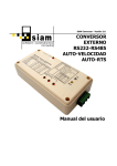
SiAM Conversor · Version 2.0
EXTERNAL
RS232-RS485
AUTO-SPEED
AUTO-RTS
CONVERTER
User manual
SiAM Conversor · Version 2.0
s iam
User manual
so ftwa r e i a ut om at is me s
mo r ve dr e
CHARACTERISTICS
•
•
•
•
•
•
•
•
•
•
•
•
•
•
•
External RS232/RS485 microcontroller-based converter with automatic transmission
detection (Auto-RTS) and automatic speed detection (Auto-Speed).
Works at 7 different speeds (2400, 4800, 9600, 19200, 38400, 57600 y 115200 bps)
with byte sizes of 9, 10, 11 and 12 bits.
Three selectable working modes: automatic transmission and reception, only
transmission, only reception.
Echo option switch.
Fully compatible with Siemens PC/PPI Cable for connection with Siemens S7-200 PLCs.
End-of-bus resistances to avoid reflexions, and pull-up and pull-down to stabilize the
RS-485 bus.
Up to 64 converters in the RS-485 bus (without repeaters).
Switches for configuration of byte size and pull-up, pull-down and end-of-bus
resistances.
Internal jumpers for configuration of loopback connections for hardware flow
control.
LED indication for external power supply, reception state, transmission state and
working speed.
Port-powered operation with connector for external 7-30VDC power supply
(optional).
DB9F connection for RS-232 port (DB9M-DB9F 1.8m serial cable optional).
Pluggable 3-way terminal block connector for RS-485 port. Other connectors available
under special request: DB9M, DB9F, RJ-45, RJ-11, RJ-12, RCA, jack, etc.
Optional DIN-rail mounting clip.
Dimensions: 100 x 50 x 25 mm
CONTENTS
•
•
•
•
•
232/485 converter.
User manual.
220 VAC to 12 VDC transformer (optional).
DB9M-DB9F 1.8m serial cable for RS-232 PC port connection (optional).
DIN-rail mounting adapter (optional).
Page 2
SiAM Conversor · Version 2.0
s iam
User manual
so ftwa r e i a ut om at is me s
mo r ve dr e
INTRODUCTION
SiAM-Conversor is a RS-232 to RS-485 communications converter with automatic detection
of transmisión direction (Auto-RTS) and automatic detection of the communications baud
rate (Auto-Speed).
In the following figure you can see the layout of the configuration switches, display LEDs
and connectors in the converter case.
1
2
5
4
6
7
1. DB9 female connector for RS-232.
2. Power supply connector.
3. RS-485 bus connector.
4. Configuration switches.
5. LED for external power supply.
6. LEDs for communication monitoring.
7. LEDs for baud rate monitoring.
Page 3
3
SiAM Conversor · Version 2.0
s iam
User manual
so ftwa r e i a ut om at is me s
mo r ve dr e
THE RS-485 BUS AND TRANSMISSION CONTROL
The RS-485 bus –conventional term for the TIA/EIA-485 norm- offers several advantages
over the RS-232:
•
•
•
•
It allows multipoint communications up to 32 nodes, while RS-232 only allows
point-to-point communications between 2 stations.
The communication distance can be increased to more than 1000 metres
(depending on the transmission speed).
Transmission speed can be much higher than in RS-232, up to 10 Mbits/s.
Higher noise immunity.
The physical layer consists in a twisted pair (shielded or unshielded) whose wires are
named 485+/485- (although they are also named TX+/TX- or A/B). A 1 bit is translated in
a positive differential voltage between 485+ and 485- higher than 0.2V (tipically 1.5V),
and, while at same time a 0 bit establishes a negative differential voltage between 485+
and 485-.
The RS-485 bus is a half-duplex shared medium where stations cannot transmit and
receive data at the same time. The bus nodes must enable their transmission drivers only
when they have data to transmit, and disable them immediately after transmission to
release the bus and allow the rest of nodes to transmit. The signal that controls the
transmission enabling is the Request to Send or RTS signal. The control of this signal in
the RS-232 ports in a PC (or any other device with an RS-232 port) is complicated,
because the serial port must be low-level programmed to ensure a short delay in disabling
RTS after transmission.
SiAM-Conversor incorporates an automatic, microcontroller-based RTS control that
guarantees the correct data transmission from the RS-232 side to the RS-485 side without
the need of programming the RTS control line in the RS-232 port.
Page 4
SiAM Conversor · Version 2.0
s iam
User manual
so ftwa r e i a ut om at is me s
mo r ve dr e
AUTO-RTS AND AUTO-SPEED WORKING MODE
In Auto-RTS mode, knowing the actual transmission speed accurately it’s very important,
because transmission deactivation delay is calculated depending on this speed. In this
mode, the converter calculates the actual transmission speed measuring pulse widths in
the RS-232 port. The detected speed will be shown in the speed monitoring leds.
Speed detection is performed dinamically, so that if the transmitting device changes the
communication speed, the converter will detect it after a short time and will automatically
adjust transmission deactivation delay.
The converter has a security mechanism in automatic speed detection mode that
automatically resets the converter and sets the detected speed to its lowest value (2400
bps) after a 5-second (approx.) interval with no activity in the transmission line.
Whenever posible, it’s convenient to program the RS-232 devices so that they wait for at
least one byte time before beginning the transmission, in order to ensure that the device
which transmitted previously has released the bus before the new transmission begins. If
this is not taken into account, communication errors can occur. At higher speeds, RTS
delay after transmission is lower than the device’s processing time and so this problem is
less important. In fact, this converter has been used to communicate with many kinds of
RS-485 devices with no related to delays.
The following table shows the minimum delay times for every speed with 9, 10, 11 and 12
bit-sized bytes.
Speed
2400 bps
4800 bps
9600 bps
19200 bps
38400 bps
57600 bps
115200 bps
Byte time
(9 bits)
3.750 ms
1.875 ms
0.938 ms
0.469 ms
0.234 ms
0.156 ms
0.078 ms
Byte time
(10 bits)
4.167 ms
2.083 ms
1.042 ms
0.521 ms
0.260 ms
0.174 ms
0.087 ms
Page 5
Byte time
(11 bits)
4.583 ms
2.292 ms
1.146 ms
0.573 ms
0.286 ms
0.191 ms
0.095 ms
Byte time
(12 bits)
5.000 ms
2.500 ms
1.250 ms
0.625 ms
0.313 ms
0.208 ms
0.104 ms
SiAM Conversor · Version 2.0
s iam
User manual
so ftwa r e i a ut om at is me s
mo r ve dr e
CONFIGURATION SWITCHES
The eight configuration switches placed if
one side of the converter case are inactive
(OFF) in upper position and active (ON) in
the lower position, as indicated by the arrow.
The default setting for the configuration
switches is shown in the picture on the right:
S1-S2-S3-S8 inactive and S4-S5-S6-S7 active.
The purpose of each one of the configuration
switches (from left to right) is described in
the following table:
S1
Switch
Function
Pull-up
S2
Pull-down
S3
End-of-bus
S4
Echo disable
S5
TX enable
S6
RX enable
Description
Activates the 390 Ω pull-up resistor to stabilize the bus. Must
be set in only one node in the RS-485 network.
Activates the 390 Ω pull-down resistor to stabilize the bus.
Must be set in only one node in the RS-485 network.
Activates the 220 Ω end-of-bus resistor to avoid reflections in
the bus. Must be turned on in the end nodes of the bus
and turned off in all the intermediate nodes.
If S4 is OFF, echo in the RS-485 bus is enabled. This means
that all the data transmitted by the converter will also be
received by itself. If S4 is ON, nothing will be received when
transmitting. The echo option can be necessary for some
particular software, but normally this switch should be
turned on.
This switch enables transmission to the RS-485 bus. If turned
OFF, no data will be sent to the bus and the device would only
be able to receive data (if S6 is ON). It should normally be
active.
This switch enables reception from the RS-485 bus. If turned
OFF, no data will be received from the bus and the device
would only be able to transmit data (if S5 is ON). It should
normally be active.
Page 6
SiAM Conversor · Version 2.0
s iam
User manual
so ftwa r e i a ut om at is me s
mo r ve dr e
Switch
S7,S8
Function
Byte size
Description
These two switches select one between the four possible byte
sizes (including data, start, stop and parity bits) according to
the following table:
S8
S7
Byte size
Possible configurations
(Data bits -Parity (Yes/No)-Stop bits)
OFF
OFF
ON
ON
OFF
ON
OFF
ON
9 bits
10 bits
11 bits
12 bits
7-No-1
8-No-1, 7-Si-1, 7-No-2
8-Yes-1, 8-No-2
8-Yes-2
If communications byte size is unknown, try all possibilities to
see which one works best.
Page 7
SiAM Conversor · Version 2.0
s iam
User manual
so ftwa r e i a ut om at is me s
mo r ve dr e
CONFIGURATION JUMPERS
1
Configuration jumpers are not accesible
from outside the converter because their
functionality is not required for most
applications. If it were necessary to set
these jumpers, the converter’s plastic
case should be open by removing the four
screws in the bottom side. They’re placed
just beside the configuration switches, as
shown in the picture on the left. Its
purpose is described in the following
table:
3
2
4
Jumper
Function
Description
J1
LED activation without If this jumper is activated (closed), the converter will turn on the LEDs
external power supply even when no external power supply is present. This is not advisable
because the current consumption with all LEDs active can be higher
than the current supplied by typical PC serial ports, and this can cause
malfunction and converter resets.
J2
RTS-CTS loopback
Connects the lines RTS and CTS in the RS-232 port.
J3
DTR-DSR loopback
Connects the lines DTR and DSR in the RS-232 port.
J4
DTR-RI loopback
Connects the lines DTR and RI in the RS-232 port.
Loopback connections (RTS-CTS and DTR-DSR-RI) can be necessary if the software that
controls the serial port requires hardware flow control. Otherwise, it’s recommended to
leave the jumpers inactive (open) to minimize current consumption.
Page 8
SiAM Conversor · Version 2.0
s iam
User manual
so ftwa r e i a ut om at is me s
mo r ve dr e
MONITORING LEDS
4
2
1
3
1. LEDs for baud rate
monitoring. These LEDs
indicate the comms baud
rate detected by the
converter, according to the
following table:
L1
L2
L3
Off
On
Off
On
Off
On
Off
On
Off
Off
On
On
Off
Off
On
On
Off
Off
Off
Off
On
On
On
On
Detected
baud rate
--2400 bps
4800 bps
9600 bps
19200 bps
38400 bps
57600 bps
115200 bps
2. LED for reception state. Turns on when data is received from the RS-485 bus.
3. LED for transmission state. Turns on when the device is transmitting data to the
RS-485 bus.
4. LED for external power supply. Indicates if an external power supply is present.
If the converter is getting power only from the serial port, it will work but no LED will be
active –unless jumper J1 is active as described in the previous page- because normally a
serial port can’t source enough current to keep all the LEDs active at the same time.
Page 9
SiAM Conversor · Version 2.0
s iam
User manual
so ftwa r e i a ut om at is me s
mo r ve dr e
CONNECTORS
1
GND
Shield
3
485-
485+
2
VIN
1. RS-232 port connector.
DB9 female connector where
a normal serial extender
cable can be connected.
2. RS-485 bus connector.
Connect here the RS-485 bus
cable (to the 485+ and485terminals) and the cable
shield
(to
the
Shield
terminal). Connecting shield
will reduce noise in the RS485 bus.
3. External power supply
connector. Connect here
the external power supply
(between 7 and 30 VDC).
The positive terminal is in the
center pin.
VIN
Shield
485-
485+
It’s possible to change the standard 3-way pluggable
terminal block connector for the RS-485 bus by a 5-way
connector which allows the connection of the external
power supply through the two additional poles. In this case,
the connection diagram would be as shown in the picture
on the right.
GND
In some custom models of the converter, the RS-485 bus connector can be of another
type like DB9 male, DB9 female, RJ-45, RJ-11, RJ-12, etc. In these cases, the connection
between lines 485+, 485- and Shield to the pins in the connector will be specified for each
particular case. In those models, the standard connector for external power supply can be
removed because power can be supplied through some of the unused pins in the bus
connector.
Don’t power the converter through the RS-485 bus
connector –in the models where it can be done- and
through the standard external power supply
connector at the same time. Only one power supply
connection can be used.
Page 10
SiAM Conversor · Version 2.0
s iam
User manual
so ftwa r e i a ut om at is me s
mo r ve dr e
PC CONNECTION
Connection between the converter and the RS-232 PC port is performed by a normal serial
port extending cable, as the following diagram shows:
VIN
GND
485+
DB9H
Conversor
DB9M
PC
485Shield
Connecting DB9 shields is optional though recommended to increase noise immunity.
Connection to serial ports with DB25M is also possible using standard DB25-DB9 adapters.
SIEMENS S7-200 PLC CONNECTION
This converter can replace Siemens communication adapter (PC/PPI Cable) for S7-200
CPUs. Moreover, no external power supply is required in this case because the CPU
supplies 24VDC through its PPI port. The connection is described in the following diagram:
VIN
GND
DB9H
CPU-S7
485+
DB9H
Conversor
485Shield
For short distance connection to an S7-200, it’s recommended to use an specific version of
the converter with a DB9 male connector which allows direct connection to the PLC and
powering the converter with only a standard serial port extender cable.
Page 11
SiAM Conversor · Version 2.0
s iam
User manual
so ftwa r e i a ut om at is me s
mo r ve dr e
STANDARD RS-485 DEVICE CONNECTION
Standard RS-485 devices with DB9 connectors tipically assign 485+ and 485- signals to
pins 8 and 3. So, the connection diagram is just like the one in the previous page for the
Siemens S7-200, removing the power supply and ground signals (pins 7 and 2).
Specific versions of the converter can be requested -with any kind of connectors- ready to
connect to any RS-485 device, by specifying the type of connector to use and the
correspondence between the RS-485 and power signals and the pins in the connector.
Page 12
SiAM Conversor · Version 2.0
s iam
User manual
so ftwa r e i a ut om at is me s
mo r ve dr e
FREQUENTLY ASKED QUESTIONS
•
The converter is not receiving anything and the reception LED is always on.
Check that the 485+ and 485- cables have been correctly connected and have not
been swapped. Check also end-of-bus, pull-up and pull-down configuration switches.
End-of-bus resistance must be turned on in the first and the last device in the RS-485
bus. Pull-up and pull-down resistances must be turned on in only one device in the
bus.
•
The converter is not functioning properly when powered only from the serial
port.
The converter gets its power from the RTS and DTR lines in the RS-232 port. The
software that’s controlling the port must activate these two lines so the converter can
work without external power. If the software is not activating these lines or can’t be
configured to do so, then the converter will need an external power supply.
Even in the case where RTS and DTR lines are active, there can still be problems. PC
serial ports can source a very limited amount current. In some cases –like in notebook
PCs- the current is so low that the converter can’t work at all. In normal serial ports
the converter should work fine but care must be taken to reduce its consumption as
much as possible. The converter automatically detects the absence of an external
power source and turns off all the LEDs -unless jumper J1 is active- but if this is not
enough, the following actions are recommended:
•
•
•
Disable pull-up and pull-down resistors in the converter. Those resistors, if
necessary, can be activated in any other node in the bus.
Disable the end-of-bus resistor. Normally it’s not necessary unless the baud rate
is 38400 bps or higher.
Disable loopback connections for hardware flow control.
Page 13
SiAM Conversor · Version 2.0
s iam
User manual
so ftwa r e i a ut om at is me s
mo r ve dr e
ELECTRIC CHARACTERISTICS
Parameter
Units
V
mA
W
ºC
%
Supply voltage
Supply current
Power consumption
Operating temperature
Operating humidity
Minumum
7
10
0,07
0
10
Maximum
30
150
4,5
50
90
Minimum
--2400
Maximum
64
1152001
COMMUNICATION CHARACTERISTICS
Parameter
Number of stations in the RS-485 bus
Communication speed
Units
--bps
1
Baud rate of 115200 bps is in the limit of the conversor performance and may present some error rate
which can be overcome by retries by the protocol in the data link layer.
Page 14
SiAM Conversor · Version 2.0
s iam
User manual
so ftwa r e i a ut om at is me s
mo r ve dr e
COPYRIGHT
This product with all its components and this manual are property of Software i
Automatismes Morvedre S.L.L.. Total or partial reproduction of design, program, electronic
board or manual is forbidden. Any action against this statement will be prosecuted
according to intellectual property laws.
June 2004
Page 15
s iam
so ftwa r e i a ut om at is me s
mo r ve dr e
Software i Automatismes Morvedre, S. L. L.
Vent de Ponent, 22
46520 Puerto de Sagunto
Valencia (Spain)
www.siam.es
[email protected]