1
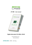
Semiconductor analyser AS4002P User Manual Copyright Ormelabs (C) 2010 http://www.ormelabs.com AS4002P, User Manual 1 CONTENTS SECTION Page SECTION 1: Introduction...................................................................... SECTION 2: Features............................................................................ SECTION 3: Component analysis......................................................... 3.1: Bipolar transistors........................................................ 3.2: Faulty semiconductors................................................. 3.3: Junction Field effect transistors................................... 3.4: Enhancement MOSFET Transistors ……................... 3.5: Depletion MOSFET .................................................... 3.6: Thyristors and triacs..................................................... 3.7: Diodes........................................................................... 3.8: Diodes networks .......................................................... 3.9: Unijunction transistors.................................................. SECTION 5: Annexes ............................................................................ Annex 1: Calibration............................................................ Annex 2: Optocouplers analysis .......................................... Annex 3: Jack plug pinout ................................................... Annex 4: Optocouplers interface schematics .............. ....... Annex 5: Technical specifications ....................................... 3 3 4 4 7 7 8 9 10 10 11 12 13 13 14 14 15 15 AS4002P, User Manual 2 SECTION 1: INTRODUCTION The AS4002P Semiconductor Analyzer is a powerful instrument that can identify easily and accurately a large number of components. SECTION 2: FEATURES Automatic component identification ⇒Bipolar transistor, with or without protection diode and/or B-E shunt resistor ⇒Darlington transistors ⇒Enhancement and Depletion mode MOSFETs ⇒Junction FETs ⇒Triac ⇒Thyristors ⇒Diodes ⇒Unijunction transistors ⇒Faulty components (short-circuits) Automatic pinout identification for all the above components Current gain measurement for bipolar transistors Test current display VBE/IB measurement Collector leakage current measurement Automatic recognition of semiconductor type for bipolar transistors (Ge/Si) Detection of Collector/Emitter diode and Base-Emitter shunt resistor Gate threshold voltage for MOSFETs Test current measurement Gate threshold, IDSS and RDSON for JFETs Diode forward voltage and forward current measurements Diode leakage current measurement Low power Darlington recognition with pinout identification Low power Triac and thyristor identification Unijunction transistor identification with pinout and RBB/η measurement Internal short circuit detection and resistance measurement AS4002P, User Manual 3 SECTION 3 : COMPONENT ANALYSIS The AS4002P Semiconductor Analyzer is designed to analyze out-of-circuit and un-powered components. This is necessary to avoid erroneous component detection and errors in parameters measurements. Three-terminals components can be connected in any fashion to the probes. Diodes should be connected to the left and right probes. When the unit is powered on, the display shows the revision of the software for two seconds and the analysis begins. If no semiconductor is connected to the unit or if the component is not detected, the following message will be displayed: When a component is detected, the first line shows the component type, and up to two parameters. The second line shows the pinout and, for some components, a supplementary parameter. For some components the analyzer shows successively different screens with different parameters. The analysis is done in real time, you just have to connect the component to the probes and the unit displays in less that one second the result of the analysis. The backlight of the unit is powered when a valid component is detected, and powered off when no component is connected. The backlight is powered off also when the component is connected for more than 30 seconds, in order to conserve battery life. 3.1 Bipolar transistors A bipolar transistor (BJT) is a semiconductor device commonly used for amplification. Physically, a bipolar transistor amplifies current, but it can be connected in circuits designed to amplify voltage or power. There are two major types of bipolar transistors, PNP and NPN. The ratio of the collector current to the base current, called current gain or HFE, is on the order of 100 for most types of BJTs. Bipolar transistors can be fabricated to match with like devices much better than FETs, making them useful for high precision analog circuit design. This makes them well suited as components in op-amps and discrete transistor amplifiers where, combined in precisely-matched pairs, they form input structures called current mirrors. Some high power or high frequency BJTs have an internal diode between collector and emitter terminals. AS4002P, User Manual 4 The AS4002P Semiconductor Analyser can detect two different kinds of semiconductors: Germanium or Silicon. The first type are older and are not common. The analyser can also detect the presence of an internal diode, symbolized by the pictogram as well as a base-emitter shunt resistor. All the parameters are displayed in three different panels. The first panel displays the HFE (static current gain) of the transistor. The AS4002P can measure current gain in the range of 5 to 999. The current gain varies according to the operating condition of the transistor. The polarization of the transistor under test is not fixed but depends on the actual HFE value. The collector test current is displayed for reference. This will be between 1.5mA and 12mA. The unit can also detect low power Darlington transistors, but in this case the current gain is not displayed. Power Darlington transistors will generally not be recognized by the analyser. These transistors usually contain a base-emitter shunt resistor which provides an additional path for the base current. The HFE value displayed can be different than the value encountered in a real world circuit with different values of collector current and collector voltage. The displayed value is very useful however for comparing transistors of a similar type for the purposes of gain matching or fault finding. The determination of the H FE of high power transistors uses higher base current. In this case a star ‘*’ is displayed after the beta value. The value can be inaccurate if the test current is above 10mA. This is also the case when a transistor with an internal resistor is recognized. This example shows the first screen for a NPN Silicon bipolar transistor with internal protection diode. This example shows the display when a PNP Germanium transistor is detected. The following screen is displayed when a NPN Darlington type is detected. The current gain is not displayed. AS4002P, User Manual 5 This screen shows an inaccurate H FE measurement of an ESM113 transistor with internal diode and shunt resistor symbolised by the symbols « RS » and . The actual gain is higher than 31. )Please note that the analyser will determine that the transistor under test is a Germanium if the base-emitter voltage drop is between 0.1V and 0.5V. If this voltage is between 0.5V and 1V the transistor will be detected as Silicon type. Between 1V and 2V the analyser will determine that the transistor is a Darlington type. The second panel shows the VBE/IB values when HFE measurement is realised. The third and last screen shows the collector leakage current ICEO. The collector leakage current is measured when the base is connected to the emitter through a resistor of 100kΩ. The current flowing across this resistor is low compared to the current flowing into the base. Thus the current displayed is near the real ICEO current measured normally with the base left open. One can determine the ICBO current by dividing the ICEO result by the HFE value. Two automatic ranges are provided in the unit. The first range goes up to 25µA with 100nA resolution. The second range goes to 500µA with 1µA resolution. The example shows the display with an old Germanium AC130 transistor which exhibits a collector leakage current of several µA. )Please note that the unit cannot identify bipolar junction transistors with collector leakage current above 500µA. AS4002P, User Manual 6 3.2 Faulty semiconductors Generally, a defective semiconductor presents one or two junctions shortcircuited. In such case, the analyser would display the affected terminals and the resistance value of the short. )Please note that the analyser will determine a short-circuit if the measured resistance between two terminals is below 50Ω for the two current directions and if the third terminal does not influence the value. The test current for the resistance measurement is about 12mA. 3.3 Field Effect Transistors (JFET) With no gate voltage, current flows easily when a voltage is applied between the source and drain. This current is called the Saturation Current, symbolized by the IDSS symbol. The current flow is modulated by applying a voltage between the gate and source terminals. N-Channel JFETs require a negative voltage on their gate with respect to their source, the more negative the voltage, the less current can flow between the drain and source. When the voltage reaches the voltage threshold of the transistor the drain current becomes zero. With low drain-source voltage, the channel is a gate to source voltage dependant resistor (linear region). With no gate to source voltage this resistance is called RDSON. Unlike MOSFETs, JFETs have no insulation layer on the gate. This means that the gate to source resistance is very high if the junction is reverse biased, but the gate current can rise if the junction is forward biased. Unlike other semiconductor testers, the analyser has an original method which permits the determination of 3 parameters: VTO, IDSS and RDSON. The internal structure of JFETs is essentially symmetrical about the gate terminal, this means that the drain and source are indistinguishable by the unit. However the analyser will show the drain and source terminals according to the parameter measurements. The permutation of the drain and source terminals of the JFETs will not change the pinout displayed, but new parameters will be measured according to the new configuration. Thus one can verify the symmetry of the transistor by comparing the values for the two configurations. The three parameters are displayed successively every 4 seconds. AS4002P, User Manual 7 Threshold voltage measurement The threshold voltage is negative for N-channel JFETs and positive for P-channel JFETs. Maximum threshold voltage measurement is fixed to ±20V. Voltage resolution is 10mV for values up to ±9.99V and 100mV above. The example below shows the threshold voltage screen for a N-channel JFET. Note that the test current is also represented. The accuracy of the measurement is ±100mV typical. This example shows the threshold voltage measurement for an NChannel JFET Saturation current measurement The saturation current can be measured from 0 to 99.9mA. Resolution is 10 µA for current up to 10mA and 100µA above. With low IDSS transistors (under 2 mA) the unit will show 0.00mA. On resistance measurement The AS4002P can measure RDSON value from 0 to 999Ω with 1Ω resolution. With low IDSS transistors the unit can show unstable values or « --- ». 3.4 Enhancement mode MOSFET MOSFET stands for Metal Oxide Semiconductor Field Effect Transistor. Like JFET, they are available in two main types, N-Channel and PChannel. Most modern MOSFETs are of Enhancement Mode type, meaning that the bias of the gate-source voltage is always positive (for N-channel types). The other (rare) type of MOSFET is the Depletion Mode type which is also recognized by the analyser. MOSFETs have an insulated gate that results in negligible gate current for both positive and negative gate-source voltages. An important feature of a MOSFET is the gate-source voltage at which conduction between the source and drain starts. Below this value the transistor is off and no current can flow across the drain to source terminals. An inherent body diode is present in all enhancement mode MOSFET. AS4002P, User Manual 8 The AS4002P detects that drain-source conduction has started when it reaches about 2mA. The screen gives information about the type of MOSFET detected, the gate-source threshold voltage and the pinout of the transistor. Like bipolar transistors, the test current is also displayed on the second line. Here the AS4002P shows the results when a BUZ11A N-Channel MOSFET is under test. Here the AS4002P shows the results when a IRF9520 N-Channel MOSFET is under test. )The maximum gate current is fixed to 0.5µA. In order to obtain reliable results the instrument should be kept in a dry environment, as humidity can generate parasitic currents in the surface of the printed circuit board which can lead to erroneous detection of MOSFETs 3.5 Depletion mode MOSFET Depletion mode Mosfets are similar to the JFET, except that the gate is insulated. The transistor is conductive when no voltage is applied to the gate, and as the n-channel jfet the voltage must be below the threshold voltage in order to turn off the device. The instrument detects only nchannel device, the other one is very rare. Here the instrument shows the result when a BSS 229 transistor is connected to the input. Dual-gate transistors like BF961 can be tested by connecting the two gates together. AS4002P, User Manual 9 3.6 THYRISTORS (SCR) and TRIACs Thyristors are switching devices that don’t require any control current once they are turned on. When a small control pulse of gate current is applied, the SCR conducts only in the forward direction, the same as any conventional rectifier. When that pulse is removed the thyristor continues to conduct, assuming a minimum holding current is maintained. Thyristors operates in only one quadrant (anode and gate positive). Triacs operates in 3 or 4 quadrants, the analyser tests the triac on two quadrants. Sensitive low power thyristors (Silicon Controlled Rectifiers-SCRs) and Triacs can be easily identified and analysed with the AS4002P . Triac operation is very similar to that of thyristor and can be distinguish from it by the analyser. Thyristor terminals are the anode, cathode and the gate. For a triac the terminals are MT1, MT2 and gate (displayed T1, T2 and G by the analyser). MT1 is the terminal with which the gate current is referenced. Here the analyser shows the results when a TS420 thyristor is under test. Here a MAC97A8 triac is under test. )The test currents used by the AS4002P are low (<12mA) to eliminate the possibility of damage to a vast range of component types. Some thyristors and triacs will not operate at low currents and these types cannot be analysed with this instrument. 3.7 DIODES The diode (or any semiconductor junction) should be connected to the left and right test clips. The analyser three successive tests on the diode with the results displayed successively every 5 seconds. The first screen gives the forward voltage, the pin-out and the test current for a limiting resistor of about 400Ω, which gives a maximum current around 12mA. The example below shows the first screen for a red LED. AS4002P, User Manual 10 The next screen shows the same information but with a limiting resistor of 10kΩ, which gives a maximum current of 800µA. The same LED connected to the instrument gives lower forward voltage and current. The last screen shows the leakage current measurement and the absolute reverse test voltage. Working junctions should not introduce any leakage current. Germanium junctions can exhibit low leakage current. The example below gives the result for a base-emitter junction of an old OC140 Germanium transistor. This test is useful in detecting bad junctions which appear correct with other tests. Some special components like photo-diodes can also be checked with this test. The maximum leakage that the analyser can measure is 25µA. Above this value the display shows « --- ». Measurement resolution is 100nA. )In order to obtain reliable leakage current values the instrument should be kept in a dry environment, as humidity can generates parasitic currents in the surface of the printed circuit board. 3.8 DIODE NETWORKS The analyser detects a component with 2 junctions but not being a valid transistor. It could be a diode network or or any component not corresponding to a valid transistor. In this case, the analyser indicates the common point by the symbol 0, the 2 others with letters A and K according to the case it is an anod or a cathod. The analyser display for a diode network. Here, the common point is in the middle, one diode having its cathod on the left and the second its anod on the right. 3.9 UNIJUNCTION TRANSISTORS AS4002P, User Manual 11 B2 UJT N E B1 The unijunction transistor is more a thyristor than a transistor. It has one junction and was once referred to as a double-base diode. The UJT, unijunction transistor, does not conduct until a peak voltage, V P, is reached. At that time the emitter conducts, resulting in a positive pulse at B1 and a negative pulse at B2. The threshold voltage VP depends on the voltage between the bases and the Intrinsic Resistor Ratio η. When the emitter is below the threshold voltage, the B1-B2 channel acts as a resistor RBB., generally between 5kΩ and 10kΩ . The unit does not recognize UJT transistors with RBB values under 100Ω or above 20kΩ. The analyser detects the pin-out and measures these two parameters. The η measurement takes a few seconds to stabilize. AS4002P, User Manual 12 SECTION 4: ANNEXES Annex 1: Calibration The purpose of the calibration is to establish the resistances of the analog switches. The measurement of these resistances is done by an automatic process. When the unit is powered on without calibration, the unit shows this opposite screen. In this case, the unit takes default values for the internal calculations. The measurements are not accurate, and some components might not be determined. To enter calibration mode, place a short at the ST1, and short the three test terminals together. Apply power and this opposite screen appears. Remove the short at ST1 and the self-calibration starts. The unit performs three resistance measurements and displays their values. These values should be between 100 and 200Ω and are stored in memory. Calibration is only required once but can be performed as often as desired. Your instrument is now ready for use. Annex 2: Optocoupler analysis The OP1 module allows the detection and the Current Transfer Ratio measurement of most standard optocouplers. The module without any component must be connected to the analyser before power-up. When the analyser is powered on, the module is recognized by the tester and the screen shows the opposite message. If no component, or a faulty component, is detected the analyser should display this opposite screen. When a valid optocoupler is plugged in to its corresponding socket, the analyser would show this screen. AS4002P, User Manual 13 The first line shows the Current Transfer Ratio. This value, expressed in %, is the ratio between the output transistor collector current and the input LED current. Measurement range is 1% to about 600%. Maximum output current is 10mA. The second line shows the LED current and the forward voltage. Annex 3 : JACK PLUG PINOUT You can realize your own cord thanks to the pinout below. Right Middle Left M R L Annex 4 : OPTOCOUPLER INTERFACE BOARD SCHEMATICS LEFT 4 terminals optocouplers D1 1N4148 RIGHT 6 terminals optocouplers C1 10µF R1 100k 8 terminals optocouplers MIDDLE AS4002P, User Manual 14 Annex 5: TECHNICAL SPECIFICATIONS Reference Temperature: 25°C Parameter Min. Peak test current across unknown Peak test voltage across unknown Measurable transistor gain HFE Transistor HFE accuracy Transistor VBE accuracy -12mA -5.1V 5 VBE for Germanium identification VBE for Silicon identification VBE for Darlington identification Transistor collector-emitter test current Transistor collector-emitter test current Acceptable collector leakage Base-emitter shunt resistor threshold MOSFET gate threshold range MOSFET gate threshold accuracy 0.1V 0.5V 1.0V 0.25mA MOSFET drain-source test current MOSFET maximum gate current JFET RDSON range JFET RDSON accuracy JFET IDSS range JFET IDSS accuracy JFET VTO range Thyristor/Triac gate test current Thyristor/Triac load test current Diode limiting resistor #1 Diode limiting resistor #2 Typical Max. Note 12mA 5.1V 999 1 1 ±2% ±2 ±2% ±20mV 0.5V 1.0V 2.0V 12mA 2.0mA 2 0.5mA 50kΩ 3 0.1V 4.9V ±2% ±20mV 2mA 4 1µA 1Ω 999Ω ±5% ±10Ω 0.2mA 99.9mA ±5% ±0.1mA -20V 20V 10mA 10mA 400Ω 10kΩ AS4002P, User Manual 15 5 ±2% ±20mV Diode forward voltage accuracy Diode leakage current range UJT RBB range UJT RBB accuracy UJT η range UJT η accuracy Battery type Battery voltage range Low Battery voltage warning Inactivity backlight shutdown Operating temperature range 1. 2. 3. 4. 5. 6. 7. 0.0µA 100Ω 25.0µA 20kΩ 6 ±3% ±100Ω 15% 7V 85% ±2% 9V-LR622 9V 7V 30 secs 0°C 7 15V 50°C Between any pairs of test clips. HFE = 100, Silicon transistor Collector-emitter voltage of 4.0V Actual test current depending of threshold voltage: ID = (5-VTO)/1.1kΩ Typical accuracy, IDSS > 2mA. Reverse voltage is 5V if IR = 0µA, 2.5V if IR = 25.0µA VBB = 5.0V AS4002P, User Manual 16 OrmeLabs SARL 1, Allée des rochers 94045 Créteil , FRANCE Web : www.ormelabs.com Email : [email protected] Tel: +33 (0) 951 23 74 80 AS4002P, User Manual 17