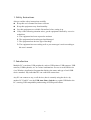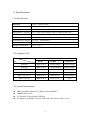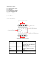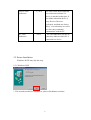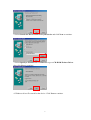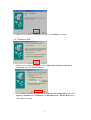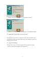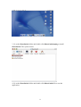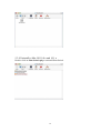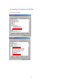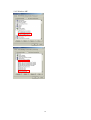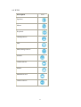
1
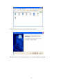
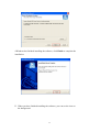
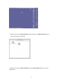
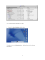
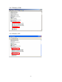
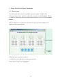
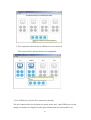
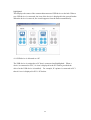
User’s Manual
USB Auto Share Switch
1. Safety Instructions -----------------------------------------------2
2. Introduction --------------------------------------------------------2
3. Features ------------------------------------------------------------3
4. Specification -------------------------------------------------------4
5. Installation ---------------------------------------------------------5
6. Share Switch Software Functions --------------------------22
7. Cascading USB consoles ------------------------------------32
8. Certification ------------------------------------------------------32
9. Disclaimer --------------------------------------------------------33
1
1. Safety Instructions
Always read the safety instructions carefully
Keep this user’s manual for future reference
Keep this equipment away from humidity
Lay this equipment on a reliable flat surface before setting it up
If any of the following situation arises, get the equipment checked by a service
technician:
A. The equipment has been exposed to moisture
B. The equipment has been dropped and damaged
C. The equipment has obvious sign of breakage
D. The equipment has not working well or you cannot get it work according to
this user’s manual.
2. Introduction
Multiple PC’s can share USB peripherals, such as USB printers, USB scanners, USB
cameras, USB keyboards, etc. in various combinations. Access to each USB device
via a Windows Application Program that displays the status and type of each USB
device attached. Any individual PC can control all connections.
Any PC can connect to any, or all devices, that is currently using the device by
another PC. Each PC sees the USB Auto Share Switch as a regular USB hub to the
PC, assuring USB compatibility and meeting all USB specifications.
.
2
3. Features
Multi PC’s share multi port USB hub
Self-power type hub
Each PC sees USB Auto Share Switch as an independent, multi-port USB hub
Fully compliant with the USB Specification 1.1
Over current detection and prevention
LED indicators for active ports
Automatic printer detection and re-connection
Software and manual selectable connection
Assigning USB devices to any of the connected PCs by drag and drop
Renaming PCs
Locking and unlocking of USB devices
Possibility to run multiple instances to use devices connected to more than one
hub
Printer functionality
3
4. Specifications
4.1 Specification
Function
USB 1.1 Share Switch
Power
Self-power mode
Upstream Connectors
2 or 4 type B receptacles
Downstream Connector 2 or 3 Type A Receptacles with or without printer port
Port Selection
Software
Housing
Plastic
External Power Supply
5V/2.5A switch power
Operating Temperature
5OC ~ 40OC
Storage Temperature
-20OC ~ 60OC
4.2 Supported O.S.
Functions
O.S.
USB Auto Switch
HUB
Printer
Vendor Supply
Switch AP
Win 98se
Built in O.S.
Vendor Supply
Win ME
Built in O.S.
Vendor Supply
Vendor Supply
Win 2000
Built in O.S.
Built in O.S.
Vendor Supply
Win XP
Built in O.S.
Built in O.S.
Vendor Supply
Mac 9.x to 10.1.x
Built in O.S.
Built in O.S.
Vendor Supply
Mac 10.2.x up
Built in O.S.
Built in O.S.
N/A
4.3 System Requirement
IBM Compatible Pentium-233 MHz or faster and MAC.
64MB RAM or more
PC and MAC with available USB port
OS Support : Win98SE , Win Me, Win 2000 , Win XP and MAC 9.0 up.
4
4.4 Package Content
USB Auto Share Switch
USB Cable
Switching Power Adapter
Quick Installation Guide
Software CD Driver
5. Installation
5.1 Install USB Hub
Upstream Connect to PCs
Power Jack
PC LED Indicators
Connects to Printer
Device LED Indicators
Downstream Connect to Devices
FUNCTION
Upstream Ports
NUMBER
DESCRIPTION
2 or 4
(USB B-Type Connector)
Use USB Cable with A-B plug to
connect to the PCs.
Downstream
Ports
2 ,3 or 4
( USB A-Type Connector )
Connect to USB devices and a
Printer
Printer Port
1
Printer Port
Power Jack
1
Connect to Power adapter.
5
Device LED
Indicators
PC LED
Indicators
2 ,3 or 4
The LED’s near the downstream
port connectors indicate if a
device is attached to that port. It
also blinks when that device is
busy. Devices like mice,
keyboards, and hubs are always
"busy" even when they are not in
use since they constantly
communicate with the PC.
4 or 2
I The LED indicators near the PC
connectors indicate which PC is
connected to a device.
5.2 Printer Installation
Windows 2K/XP may skip this step.
5.2.1 Windows 98SE
1. This wizard searched for new drivers, please click Next to continue.
6
2. Select Search for the best driver for your device and click Next to continue.
3. Select Specify a location and click Browse to go to CD-ROM \Printer Driver
then click Next to continue.
4. Windows driver file search for the device. Click Next to continue.
7
5. Windows has finished installing the software. Click Finish to continue.
5.2.2 Windows ME
1. Windows has found new hardware. Select Specify the location of the driver
[Advance] and click Next to continue.
2. Select Search for the best driver for your device [ Recommended ] and select
Specify a location and click Browse to CD-ROM driver \ Printer Driver then
click Next to continue.
8
3. Windows driver searches for the device. Click Next to continue.
4. Windows has finished installing the new hardware. Click Finish to continue.
5.3. Install and Uninstall Share Switch Software
The USB Share Switch software is supplied on a CD. The CD contains all the
executables, the online help, and the release notes. The installation is carried out
through the Setup program.
5.3.1 Install to Windows
1.Double click on Setup.exe in the installation CD, the installation program
guides you through the installation of the application.
9
2. Do not select any option and click Next to continue.
3.Windows driver file search for the device, and click Next to continue.
10
4.Windows has finished installing the software, click Finish to complete the
installation.
5. When you have finished installing the software, you can see the icon on
the background.
11
5.3.2 Install to Mac OS 9.X
1.copy the file ShareSwitch.sit to the hard drive.
2. Double-click on the file ShareSwitch.sit, which will create a folder by name
ShareSwitch.
12
3. Double-click on the ShareSwitch folder and copy the ShareSwitch folder to
desired location in hard disk.
4. Double-click on the ShareSwitch file in the ShareSwitch folder to run the
application.
13
5.3.3 Install to Mac OS 10.0.x and 10.1.x
1. Copy the file ShareSwitch.sit to the hard drive.
2. Double-click on the file ShareSwitch.sit, which will create a folder by name
ShareSwitch.
14
3. Go to the ShareSwitch folder and double-click ShareSwitch.mpkg to install
ShareSwitch. The system restart.
4. Go to the ShareSwitch folder and double-click ShareSwitch file to run the
application.
15
5.3.4 Uninstall to Mac OS 10.0.x and 10.1.x
Double-click on ShareSwitch.pkg to uninstall ShareSwitch
16
5.4. Installation Verification of USB Hub
5.4.1 Windows 98SE
17
5.4.2 Windows ME
18
5.4.3 Windows 2000
5.4.4 Windows XP
19
6. Share Switch Software Functions
6.1 Main Screen
The main screen shows four PCs and their respective baskets. Each PC has
collection of four boxes, which are collectively referred to as the PC Basket. Below
of all the PC Baskets the four boxes aligned horizontally is referred to as the General
Basket.
When a USB device is connected to the hub, then the icon of that USB device is
displayed in the general basket.
Following are few possible scenarios:
1. Neither PCs nor USB devices connected to the hub
None of the PC baskets are highlighted.
20
2. PCs connected to the hub but no USB devices are connected
The connected PCs and their baskets are highlighted.
3. Few USB devices and few PCs connected to the hub
The four connected devices (keyboard, joystick, mouse and other USB devices in the
sample screenshot) are displayed in the general basket and two connected PCs are
21
highlighted.
This displays the status of the connected/unconnected USB device to the hub. When a
new USB device is connected, the icon of the device is displayed in the general basket.
When the device is removed, the icon disappears from the basket automatically.
4. A USB device is allocated to a PC
The USB device is assigned to a PC that is connected and highlighted. When a
device is connected to a PC, it's icon is displayed in the PC basket (provided the
driver for the USB device is installed). For example, If a printer is connected to PC1
then it's icon is displayed in PC1's PC basket.
22
6.2 Drag and Drop a USB device
Using the drag and drop feature, any USB device can be assigned to any of the
connected PCs.
A PC basket is highlighted when a PC is connected to the hub and remains
unhighlighted if it is not.
For example, the general basket has a hub which is unassigned to any PC. Below are
the steps to assign the hub to a PC:
1. Select the USB hub from the general basket.
2. Drag the USB hub and drop it into a highlighted PC basket area. When the
USB hub is dropped into the PC basket, the icon of the device is displayed in
the PC basket.
The name of the USB device is displayed below the icon while it is dragged.
23
6.3 Locking a USB device to a PC
If you want to assign a device to a particular PC for exclusive use, the lock/unlock
mechanism can be used. To lock a device,
1. Position the cursor on the USB device in the PC basket and right-click.
2. The background of the icon changes from blue to red when a device is locked.
Unlocking
To unlock a device, right-click on the locked icon. The background of the icon
changes from red to blue when a device is unlocked. This status is displayed accross
all the PCs. If some other user tries to use a device which is locked and currently in
use, then a message is shown saying that the device is being used by some other user.
24
6.4 Host PC
When the USB Share Switch application is run for the first time, it automatically
names the PC it is being run on as "Host PC". For example, if your PC is connected to
PC3 (port3) of USB Share Switch hub, the software running on your PC names PC3
as "Host PC". You can easily recognize your PC and rename it as you wish.
25
6.5 Renaming a PC
Each of the PCs is assigned a name such as "PC a", where "a" changes according to
USB Share Switch’s port number. For example, If a PC is connected to port 4 then it
will be named as "PC 4".
PCs can be renamed for easy identification.
To rename a PC:
1. Select PC Name from the Edit menu. An edit box appears on the top of a PC.
2. Enter the required name and press Enter or the Tab key or click outside the
edit box.
3. Press Esc to retain the original name.
26
6.6 Multipie Instances
The USB Share Switch can be connected serially or parallely to a computer. This
concatenation can go up to a maximum of 5 levels.
To access the USB devices not directly connected to the first hub in hierarchy, the
Multiple Instances feature of USB Share Switch can be used.
To connect a hub to a PC:
1. Select the USB Share Switch icon from the general basket.
2. Drag the hub icon from the general basket and drop it into a highlighted PC
basket. When the hub is dropped into the PC basket, the icon of the hub is
displayed in the PC basket.
3. Double-click on the hub in the PC basket. One more instance of the
application is started which displays the connection status of the connected
hub, i.e. the PCs and the devices connected to the hub.
27
6.7 Printer Functionality
If only one printer is connected to the hub, it is considered as the default printer and is
shown in all the active PC baskets.
To implement printer functionality,
•
•
Configure the USB Printer on all the PCs, which are connected to the USB
Share Switch.
After configuring the USB Printer, it should to be set to the default printer on
all the PCs connected to the USB Share Switch.
If the printer is not connected to a particular PC, the driver for a USB Printer should
allow a user to spool a job for printing. If the driver allows a user to spool a job to the
USB Printer, which is already configured but not connected to the PC then the USB
Share Switch software connects the USB Printer to that PC when a job is queued up
automatically if the printer is not busy printing on some other PC.
When a USB Printer is connected to a PC where the user has configured the driver,
the USB Share Switch displays an printer icon in all PC baskets only for the PCs
connected to the USB Share Switch and corresponding general basket. All the PCs
connected to the USB Share Switch should be running the USB Share Switch
software.
If the icon is generic i.e. if the driver is not configured or USB Share Switch is not
running on a particular PC where the printer is connected and the user has dragged it
to the PC basket, the USB Share Switch recognizes it as the default USB
Printer. The default printer is displayed in all the PC baskets that are connected to
the USB Share Switch and corresponding general basket.
You can give a print command from any PC connected to the USB Share Switch. If
the default printer is not busy, it automatically assigns that PC and the job is
executed. If the default printer is busy printing on some other PC, the USB Share
Switch waits for the job on the other PC to get over and then assigns the default
printer to the current PC. This depends on the spooling feature of the driver.
28
If more than one printer is connected to the USB Share Switch software, all the printer
icons are shown in the General Basket. The default printer has to be updated by
double-clicking on the printer icon. After double-clicking on the printer icon, the
printer is shown in the PC basket of all the active PCs.
After the default USB Printer is identified by the PC to which the USB Share Switch
hub is connected, the printer icon is displayed in all the active PC baskets and
corresponding general basket.
29
After the default printer is selected, the above mentioned functionality of the default
printer is supported by the USB Share Switch software.
The printer name can be checked by placing the cursor on the default printer icon.
30
6.8 ICON
Icon
Description
Speakers
Mouse
Keyboard
Gaming Device
Hub
Mass Storage Device
Scanner
Camera Device
Printer
Ethernet Device
Generic Device
31
7. Cascading USB consoles
7.1 Extending the Distance between the PC and the USB Console
There are occasions when the PC’s have to be at a distance greater than the maximum
length of a USB cable. One way to increase the distance is by placing a USB hub in
between the PC and the Sharer-A-Hub. However, this way is expensive and clumsy.
A better way is to use what is called an USB Active Extension Cable or an USB
Booster Cable. While they are called cables, they have active devices that buffer the
USB signals to allow for extended lengths. Each cable, as well as the Sharer-A-Hub,
can be considered as a hub and no more than 5 USB hubs can be placed in series.
Please notice that it can’t place a USB2.0 hub between the USB 2.0 PC and the
Sharer-A-Hub. Once you set up, the system will become to be unstable.
7.2 Apple’s iMAC
The USB Console will function with the iMAC using the manual controls. However,
the application program will only work with Windows.
8. Certification
FCC
This equipment has been tested and found to comply with Part 15 of the FCC Rules.
Operation is subject to the following two conditions:
(1) This device may not cause harmful interference
(2) This device must accept any interference received. Including interference that may cause
undesired operation.
CE – Certificate
This equipment is in compliance with the requirements of the following
regulations: EN 55 022: CLASS B
32
9 .Disclaimer
Information in this document is subject to change without notice. The manufacturer
does not make any representations or warranties (implied or otherwise) regarding the
accuracy and completeness of this document and shall in no event be liable for any
loss of profit or any commercial damage, including but not limited to special,
incidental, consequential, or other damage.
No part of this document may be reproduced or transmitted in any form by any means,
electronic or mechanical, including photocopying, recording or information recording
and retrieval systems without the express written permission of the manufacturer.
33