1
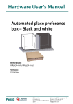
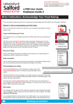
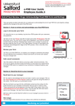
Hardware User’s Manual Atlantis automatic island Water maze References: LE820300 (76-0026) Version: V12/11/2014 Panlab, s.l.u C/Energía, 112 08940 Cornellà de Ll.(Barcelona) Spain www.panlab.com International Calls: +34 934 750 697 Domestic Call: 934 190 709 Fax: +34 934 750 699 [email protected] Limitation of Liability PANLAB does not accept responsibility, under any circumstances, for any harm or damage caused directly or indirectly by the incorrect interpretation of what is expressed in the pages of this manual. Some symbols may have more than one interpretation by professionals unaccustomed to their usage. PANLAB reserves the right to modify, in part or in total, the contents of this document without notice. 1. SYMBOLS TABLE Recognising the symbols used in the manual will help to understand their meaning: DESCRIPTION Warning about operations that must not be done because they can damage the equipment Warning about operations that must be done, otherwise the user can be exposed to a hazard. Decontamination of equipments prior to disposal at the end of their operative life SYMBOL 2. GOOD LABORATORY PRACTICE Check all units periodically and after periods of storage to ensure they are still fit for purpose. Investigate all failures which may indicate a need for service or repair. Good laboratory practice recommends that the unit be periodically serviced to ensure the unit is suitable for purpose. You must follow preventive maintenance instructions. In case equipment has to be serviced you can arrange this through your distributor. Prior to Inspection, Servicing, Repair or Return of Laboratory Equipment the unit must be cleaned and decontaminated. Decontamination prior to equipment disposal In use this product may have been in contact with bio hazardous materials and might therefore carry infectious material. Before disposal the unit and accessories should all be thoroughly decontaminated according to your local environmental safety laws. Automatic island Atlantis 2 3. UNPACKING AND EQUIPMENT INSTALATION WARNING: Failure to follow the instructions in this section may cause equipment faults or injury to the user. A. No special equipment is required for lifting but you should consult your local regulations for safe handling and lifting of the equipment. B. Inspect the instrument for any signs of damage caused during transit. If any damage is discovered, do not use the instrument and report the problem to your supplier. C. Ensure all transport locks are removed before use. The original packing has been especially designed to protect the instrument during transportation. It is therefore recommended to keep the original carton with its foam parts and accessories box for re-use in case of future shipments. Warranty claims are void if improper packing results in damage during transport. D. Place the equipment on a flat surface and leave at least 10 cm of free space between the rear panel of the device and the wall. Never place the equipment in zones with vibration or direct sunlight. The manufacturer accepts no responsibility for improper use of the equipment or the consequences of use other than that for which it has been designed. PC Control Some of these instruments are designed to be controlled from a PC. To preserve the integrity of the equipment it is essential that the attached PC itself conforms to basic safety and EMC standards and is set up in accordance with the manufacturers’ instructions. If in doubt consult the information that came with your PC. In common with all computer operation the following safety precautions are advised. WARNING • To reduce the chance of eye strain, set up the PC display with the correct viewing position, free from glare and with appropriate brightness and contrast settings • To reduce the chance of physical strain, set up the PC display, keyboard and mouse with correct ergonomic positioning, according to your local safety guidelines. Automatic island Atlantis 3 4. TABLE OF CONTENTS 1. SYMBOLS TABLE ...................................................................................... 2 2. GOOD LABORATORY PRACTICE ............................................................... 2 3. UNPACKING AND EQUIPMENT INSTALATION ........................................... 3 4. TABLE OF CONTENTS ............................................................................... 4 5. INTRODUCTION ....................................................................................... 5 6. COMPRESSOR DESCRIPTION .................................................................... 6 7. WORKING WITH THE COMPRESSOR ......................................................... 7 8. 7.1. REALISING AN EXPERIMENT ............................................................... 7 7.2. SELECTING THE DEFAULT POSITION .................................................. 9 CONNECTING THE EQUIPMENT ...............................................................10 8.1. AIR CONNECTIONS ............................................................................10 8.2. ELECTRICAL CONNECTIONS ..............................................................11 8.2.1. MANUAL MODE...........................................................................11 8.2.2. AUTOMATIC MODE .....................................................................12 Automatic island Atlantis 4 5. INTRODUCTION The LE820300 Atlantis automatic island is a platform that can be installed in Panlab’s circular pool. Said platform is activated pneumatically through a compressor provided with the platform, the air flow of this compressor also determines the rising speed of the platform. Figure 1. Atlantis automatic island The control of the Atlantis can be achieved manually or through the SMART software, a video tracking software. Automatic island Atlantis 5 6. COMPRESSOR DESCRIPTION POWER (1) OIL INPUT AND FILTER (7) ROTARY SWITCH (3) Figure 2. Compressor front and rear panel POWER: Switch to power on and off the equipment. OIL INPUT AND FILTER: ROTARY SWITCH: Switch that enable or disables the air flow JACK (6) FLOW CONTROL (4) Figure 3. Compressor side view JACK: Female connector for the button box or the SMART cable depending of the control mode. FLOW CONTROL: It regulates the air flow that passes through in consequence controlling the rising speed of the platform. Automatic island Atlantis 6 7. WORKING WITH THE COMPRESSOR 7.1. REALISING AN EXPERIMENT POWER (1) JACK(6) OIL INPUT AND FILTRE (7) ROTARY SWITCH (3) Figure 4. Compressor front and rear panel Before activating the compressor the oil deposit should be filled, otherwise permanent damages could happen. To activate the compressor turn on the POWER (1) switch and then set the ROTARY SWITCH (3) in the I position. Once the pressure reaches the selected value the compressor will stop, afterwards set the rotary switch (3) in the 0 position. Whenever the pressure decreases it must be set again to the I position. WARNING: There will be enough pressure to work for some time, is not advisable to maintain continuously the ROTARY SWITCH in the I position, as it shortens the duration of the compressor. Once the experiment is finished turn off the compressor with the POWER (1) switch. With the FLOW CONTROL (4) key the rising speed of the island can be controlled, the more flow you set the faster the island will move. You can activate the island either manual control or SMART control. To activate island manually just connect the button box to the JACK (6). If you want to use SMART I/O Automatic island Atlantis 7 control then connect the SMART isolated output cable to the JACK (6) and the other end of the cable to the SMART I/O. Automatic island Atlantis 8 7.2. SELECTING THE DEFAULT POSITION END (5) (2) Figure 5. Atlantis tube connection The steady state of the platform depends on how the air flow connections are made. IDLE STATE IN THE LOWER POSITION: To have the platform in the lower position when in steady state, the tube (2) has to be connected in the upper position of the connector. So that when the electro-valve is activated (manually or through the SMART software) it moves up until it reaches the position set previously through END(5). Once the electro-valve is off the platform will return to its idle position. IDLE STATE IN THE UPPER POSITION: For changing the behaviour explained before, swap the tubes connections that go from the electro-valve to the platform. In other words connect the tube (2) in the lower position of the connector. In this case when the electro-valve is activated the platform will descend and when it is turned off the platform will go to the upper position. Automatic island Atlantis 9 8. CONNECTING THE EQUIPMENT 8.1. AIR CONNECTIONS In the following schematic you can see how to install the cylinders with screw in the swimming pool walls. Figure 6. Air flow cylinders The required connections are described in Figure 7. Figure 7. Assembly of the Atlantis to the swimming pool Automatic island Atlantis 10 8.2. ELECTRICAL CONNECTIONS Depending on the working mode used, be it manual or automatic (SMART video tracking software), a different connection will be used for the JACK (6) connector. 8.2.1. MANUAL MODE When working in this mode a button box will be available for connecting it to the JACK (6). This button will activate the island whenever it is pressed only if the procedure explained in section 7.1 has been followed through. Figure 8. Connecting the button box to the jack connector. Automatic island Atlantis 11 8.2.2. AUTOMATIC MODE Whenever the island is to be controlled through the SMART video tracking software, the isolated output cable, SMART, should be connected to the JACK (6) and the other end will be connected to the SMART I/O. Figure 9. Connecting the SMART cable to the jack connector. Automatic island Atlantis 12