1
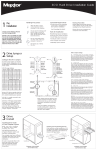
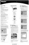
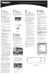
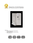
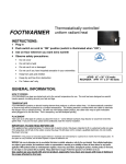
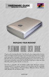
SCSI Hard Drive Installation Guide
Allow the drive to reach
room temperature before
installing it in the computer.
Do not open the ESD bag until
you’re ready to install the
drive. Handle the drive by its
sides. Do not touch the circuit
board (electronics).
Maxtor's goal is to provide you with
the most up-to-date product possible,
and we are constantly enhancing our
software and documentation to better
meet your needs. Please visit our website at www.maxtor.com to view the
latest that Maxtor has to offer!
TP - Termination Power
Pins 27-28 - Termination power ensures that there is a sufficient
power level along the entire SCSI bus. It is recommended
that the final device on the SCSI bus have the Termination
Power jumper installed. All devices in between the host and
final device typically have no jumper on Termination Power.
Note that Termination Power is not the same as on-board
termination, which this drive does not support.
Pin 27
Term Power
reserved
GND
No Wide
GND
Stagger Spin
GND
Write Protect
GND
Busy Out
+5 V
NW - No Wide
Pins 23-24 are normally open, allowing for 16-bit data transfer.
With a jumper added to the pins, negotiations can be limited
to 8-bit (narrow) data transfer.
No Connect
Force SE
GND
Delay Spin
GND
ID 3
ON
ON
OFF
OFF
ID 4
OFF
OFF
ON
OFF
ID 5
ON
OFF
ON
OFF
ID 6
OFF
ON
ON
OFF
RESERVED FOR SCSI HOST
ID 8
OFF
OFF
OFF
ON
ID 9
ON
OFF
OFF
ON
ID 10
OFF
ON
OFF
ON
ID 11
ON
ON
OFF
ON
ID 12
OFF
OFF
ON
ON
ID 13
ON
OFF
ON
ON
ID 14
OFF
ON
ON
ON
ID 15
ON
ON
ON
ON
Maxtor SCSI drives typically ship from
the factory with jumpers set to SCSI
ID 6, and termination power jumped.
SCSI ID 7 is usually reserved for the
SCSI host adapter.
blank
Fault LED
SCSI ID Bit 0
GND
SCSI ID Bit 1
GND
SCSI ID Bit 2
GND
SCSI ID Bit 3
Pin 2
Bottom View of Drive
(facing printed circuit board)
GND
Pin 1
Note: Maxtor LVD SCSI drives do not
support on-board termination. Maxtor
recommends the use of Active LVD
terminators and 68-pin twisted pair
cabling.
SCSI host adapter manufacturers
usually supply proper cabling and
termination with the purchase of an
LVD SCSI host adapter.
Attention: The Rear Jumper Option
Connector is an OEM specific connector. Most installations will never
use the jumper options on this
connector. Always configure the
drive using the jumpers at the Front
Jumper Option Connector.
Rear Jumper Option Connector
(at 68-pin SCSI connector end of drive)
SS - Stagger Spin
Pins 21-22 - For most configurations this option is not utilized.
Most current SCSI host adapters offer a Start Unit command
enable or disable, which supersedes the functionality of the
SS jumper setting. When the Delay Spin (DS) jumper is
enabled on the drive, the Start Unit command from the SCSI
host adapter will send Start Unit commands to all devices on
the bus at pre-determined intervals. This can help prevent
power supply overload when running several devices on the
SCSI bus.
WP - Write Protection
Pins 19-20 - By factory default, the drive is shipped with no
jumper on these pins, and the drive can be written to unless
protected by application software. With the pins jumped, the
drive can be used as a read-only device. This feature prevents
accidental overwrites and is useful for frequently accessed
archives and reference files.
Force SE – Force Single Ended Operation
Pins 13-14 - By factory default, the drive is shipped with no
jumper on these pins. With most system configurations, it is
not necessary to use this jumper. LVD drives are multi-mode
capable. They will automatically detect the presence of a single-ended bus and revert to single-ended mode.
DS - Delay Spin
Disable Delay Spin: No jumper across pins 11-12 (factory
default). Disabling Delay Spin allows the drive to spin up
when the system is powered up.
68 Pin SCSI Connector
J1 - 12 Pin
4 Pin Power
Option Connector
SCSI ID Bit 0
OFF
SCSI ID Bit 1
OFF
OFF
Fault LED
OFF
ON
SCSI ID Bit 2
OFF
GND
ON
OFF
GND
OFF
SCSI ID Bit 3
OFF
Busy LED
OFF
reserved
OFF
ID 1
3
Other Jumper Settings
ID Bit 3
ID 2
ID 7
• Operating system software
No Connect
ID Bit 2
• Your computer user manual
+5 V
ID 0
ID Bit 1
• Small pair of pliers or tweezers
Do not drop, jar, or bump
the drive.
Term Power
SCSI ID Jumper Settings
ID Bit O
The following tools are needed to
install your new Maxtor hard drive:
• Small Phillips head screw driver
Do not connect/disconnect
any drive cables while your
computer is turned on.
Pin 28
If specific jumper options are needed
for your system configuration, refer to
the illustrations and definitions provided
in this section.
Please refer to your computer user
manual for more information.
Tools for Installation
Front Jumper Option Connector
Configure the Drive Jumpers
Drive ID
Maxtor highly recommends that you
make a backup copy of your files before
installing the new Maxtor hard drive.
GND
2
Backup Your Data
• A full version of your operating
system (OS) is required for a
new hard drive installation
(see kit package for details)
Thank You
Thank you for selecting a Maxtor
hard drive storage product.
Drive Jumper
Setup
System/OS Requirements
No Connect
1
Handling Precautions
Pre
Installation
Enable Delay Spin: Jumper across pins 11-12. This setting
will prevent the drive from spinning up until it receives a Start
Unit command from a SCSI host adapter. Most SCSI host
adapters have the Start Unit command enabled by default in
the host adapter BIOS. Enabling Delay Spin is only necessary
when you are starting multiple devices at power on.
SCSI ID
Pin numbers 1-8 are typically referred to in pairs as A0 (pins 1
and 2), A1 (3,4), A2 (5,6), A3 (7,8). The jumper pairs will allow
configuration of SCSI ID's 0 to 15. All SCSI devices must have
an individual ID on the SCSI bus (there is no Master/Slave setting). SCSI ID 7 is usually reserved for the SCSI host adapter.
Fault LED and Busy Out Jumpers
Typical installations do not require the use of the Fault LED
and Busy Out jumpers. The Busy Out signal is usually supplied
through the PCI bus to the PC motherboard's Busy indicator
LED. If connecting the Busy Out jumper for a drive installed in
an external case, please refer to the wiring documentation supplied by the manufacturer of the case. Connection of the Fault
LED is not recommended in internal or external installations.
Drive
Install
Installing Drive Inside
of Your Computer System
Make sure your computer
is powered down before
installing the drive.
Installing 5.25-inch Mounting Brackets
If the hard drive will be installed in a 5.25inch device bay, attach mounting brackets
(available separately) to the hard drive as
shown in the figure below.
The following illustrations are
of typical computer systems and
hard drive mounting styles.
Your computer may have a different
mounting style. Please refer to your
computer user manual for more
information.
Be sure to secure the drive to the
device bay with all four screws
(included). The drive should be oriented with its printed circuit board
facing down.
Mounting Screws
Mounting Screws
Mounting Bracket
Computer with available
3.5-inch device bay
Computer with available
5.25-inch device bay
4
Cable
Hook-up
Cable Connections for SCSI Drive
Pin 1
Attach the SCSI and Power Cables
68-pin Connector
If the Maxtor SCSI drive is the only device attached to
the SCSI adapter card, attach the drive at the end of the
Ultra-2 LVD/SE cable, farthest from the SCSI adapter
card. This connector has a beveled edge and will only
fit one way. Then attach an external active LVD/SE SCSI
terminator.
68-pin Drive
Connector
Please refer to the SCSI adapter card user guide
for additional recommendations on data cable placement and SCSI termination requirements.
Attach a power cable to the power connector on the
hard drive. This connector is keyed and will
only fit one way. Check all other cable connections
before you turn on the computer.
Ultra-2 LVD/SE Cable
Caution: Do not force or rock the connectors into their
sockets on the hard drive. Push them in straight until
they are seated firmly.
Power Supply Cable
(3-Pin or 4-Pin)
DC Power
Connector
Bevel
Connect to
SCSI Host
Adapter
Card
Ultra-2
LVD/SE
Cable
Active 2 LVD
Terminator
Standard Cabling for Single SCSI Drive in System
(Ultra-2 LVD/SE cable connections)
5
Partitioning and
Formatting
Maxtor hard drives can accept nearly all
operating systems. Some operating systems have volume size limitations that
may require you to partition your drive
into multiple volumes. Please refer to
your system or SCSI adapter card user
guide for information about formatting
and partitioning the drive.
General Guidelines
• DOS/Windows 9X/ME:
Use FDISK.EXE to partition and
FORMAT.COM to format the drive.
• Windows NT/2000:
Boot your system from the installation floppy disks provided with the
OS to partition and format the drive.
If you do not have the original installation floppies, you can create them
using your Windows installation CD.
• Windows XP:
Boot your system from the Windows
XP installation CD to partition and format the drive. If your system is not
capable of booting from a CD, you
can download bootable Windows XP
installation floppies from Microsoft's
website at www.microsoft.com
• Macintosh: Most non-Apple branded
hard drives can be formatted using
the Drive Setup utility included in Mac
OS 8.6 and above. Mac OS versions
before 8.6 will require a third-party
hard drive utility such as FWB Hard
Disk Toolkit (www.fwb.com) or Intech
Hard Disk SpeedTools
(www.intechusa.com) to partition and
initialize the drive. Please visit the
FWB or Intech website for details on
these non-Maxtor software products.
6
Product
Registration
Take Advantage of the Benefits!
By registering your new Maxtor product, you’ll have the option to receive
product updates, special offers, and
other valuable information about other
data storage solutions from Maxtor.
Simply point your web browser to:
www.maxtor.com – go to the
product registration page, and complete the short questionnaire.
Maxtor Limited Warranty
Maxtor’s warranty obligations are limited to the terms set forth: Maxtor warrants to the original consumer purchaser
that new Maxtor SCSI products will be free from defects in material and workmanship for 5 years from the date of
original purchase. For replacement disk drives the warranty on the replacement drive is the remainder of the warranty
on the original drive or 90 days, whichever is longer. For SCSI disk drives obtained under the Maxtor Upgrade Program,
the warranty period is 5 years commencing on the date Maxtor ships the drive to the customer.
If you discover a defect, Maxtor will, at its option, repair or replace the product at no charge to you, provided you
return it during the warranty period, with transportation charges prepaid, to Maxtor in Dallas, TX; Bray, Ireland or
Singapore. Drives must be properly packaged in Maxtor packaging or Maxtor approved packaging to obtain warranty
service. Before returning a Maxtor product, please contact Maxtor at www.maxtor.com or 1-800-2MAXTOR (in
USA) to obtain a Return Material Authorization (RMA) number. A copy of the receipt or a bill of sale bearing the
appropriate Maxtor serial number and model number may be required for warranty service.
The warranty applies only to the Maxtor products that can be identified by the Maxtor trademark, trade name or logo
affixed to them. Maxtor does not warrant any product that is not manufactured by, for or with permission from
Maxtor. This warranty is not applicable to:
•
•
•
•
•
•
•
•
•
•
Abnormal wear and tear
Abuse, unreasonable use, mistreatment, or neglect
Damage caused during installation of the disk drive
Damage caused by the equipment or system with which the disk drive is used
Damage caused by modification or repair not made or authorized by Maxtor
Disk drives whose Maxtor Serial Number has been removed or defaced
Damage caused by use of non-Maxtor packaging
Damage caused by improper or improperly used packaging
Damage caused by lack of ESD protection
Drives that are determined to be stolen
THIS WARRANTY AND REMEDIES SET FORTH ABOVE ARE EXCLUSIVE AND IN LIEU OF ALL OTHERS,
WHETHER ORAL OR WRITTEN, EXPRESSED OR IMPLIED. MAXTOR SPECIFICALLY DISCLAIMS ANY AND ALL
IMPLIED WARRANTIES, INCLUDING, WITHOUT LIMITATION, WARRANTIES OF MERCHANTABILITY AND FITNESS FOR A PARTICULAR PURPOSE AND AGAINST INFRINGEMENT. No Maxtor dealer, agent or employee is
authorized to make any modification, extension or addition to this warranty.
MAXTOR IS NOT RESPONSIBLE FOR SPECIAL, INCIDENTAL, INDIRECT OR CONSEQUENTIAL DAMAGES
RESULTING FROM ANY BREACH OF WARRANTY, OR UNDER ANY OTHER LEGAL THEORY, INCLUDING BUT
NOT LIMITED TO LOSS OF DATA, LOSS OF PROFITS, DOWNTIME, GOODWILL, DAMAGE OR REPLACEMENT
OF EQUIPMENT AND PROPERTY, AND ANY COSTS OF RECOVERING, PROGRAMMING OR REPRODUCING ANY
PROGRAM OR DATA STORED IN OR USED WITH MAXTOR DISK DRIVES.
Some states/jurisdictions do not allow the exclusion or limitation of incidental or consequential damages or exclusions of implied warranties, so the above limitations or exclusions may not apply to you. This warranty gives you
specific legal rights, and you may also have other rights that vary from jurisdiction to jurisdiction.
Changes are periodically made to the information herein – which will be incorporated in revised editions of
the publication. Maxtor may make changes or improvements in the product(s) described in this publication
at any time and without notice.
Copyright © 2001 Maxtor Corporation. All rights reserved. Printed in the U.S.A. 12/01. Maxtor® is a registered trademark of Maxtor Corporation. Other brands or products are trademarks or registered trademarks
of their respective holders. P/N: 20171100, rev. A
www.maxtor.com