1
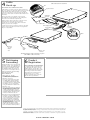
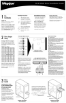
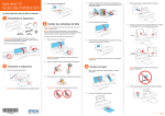
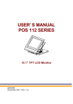
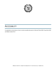
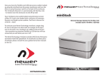
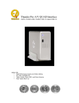
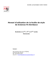
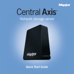
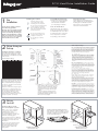
SC SI H ard D rive I nstallation G uide
1
Pre
Installation
Handling Precautions
Allow the drive to reach
room temperature before
ins talling it in the computer.
Maxtor's goal is to provide you with
the most up-to-date product possible,
and we are constantly enhancing our
software and documentation to better
meet your needs. Please visit our website at www.maxtor.com to view the
latest that Maxtor has to offer!
2
ID Bit
ID 0
OFF
OFF
FF
OF
ID 1
ON
OFF
FF
OF
ID 2
OF F
ON
FF
OF
ID 3
ON
ON
FF
OF
ID 4
OFF
OFF
N
OF
ID 5
ON
OFF
N
OF
ID 6
OFF
ON
N
OF
ID 7
ID 8
¥ Your computer us er manual
Other J umper Settings
Pin 1
Pin 2
Pin 1
SCSI ID 0
FAULT LED
SCSI ID 1
GROUND
SCSI ID 2
GROUND
SCSI ID 3
BUSY LED
NOT USED
GROUND
SCSI ID 3
SCSI ID 2
SCSI ID 1
SCSI ID 0
BUSY LED -/+
TERM POWER
+5 V
Pin 2
WRT PROTECT
STAGGER SPIN
DELAY SPIN
Pin 12
Pin 11
SINGLE ENDED
Pin 17
Pin 18
OFF
OFF
ON
ID 9
ON
OFF
OFF
ON
OFF
ON
OFF
ON
ID 11
ON
ON
OFF
ON
ID 12
OFF
OFF
ON
ON
ID 13
ON
OFF
ON
ON
ID 14
OFF
ON
ON
ON
ID 15
ON
ON
ON
ON
4 Pin Power
Connector
N ote: M axtor LVD S CS I drives do not
s upport on-board termination. M axtor
recommends the us e of Active LVD
terminators and 68-pin tw is ted pair
cabling.
A ttention: The R ear J umper Option
Connector is an OE M s pecific connector. M os t ins tallations w ill never
us e the jumper options on this
connector. Alw ays configure the
drive us ing the jumpers at the Front
J um per Option Connector
.
W P - W rite Protection
Pins 11-12 B y factory default, the drive is s hipped with no
jumper on thes e pins , and the drive can be written to unles s
protected by application s oftware. W ith the pins jumped, the
drive can be used as a read-only device. This feature prevents
accidental overwrites and is us eful for frequently acces s ed
archives and reference files .
E nable Delay S pin: J umper across pins 15-16 This setting
will prevent the drive from spinning up until it receives a Start
Unit command from a S CS I hos t adapter. M os t S CS I hos t
adapters have the S tart Unit command enabled by default in
the host adapter B IOS. Enabling Delay Spin is only necessary
when you are starting multiple devices at power on.
68 Pin SCSI
Connector
S CS I ID 7 is us ually res erved for the
S CS I hos t adapter.
S S - S tagger S pin
Pins 13-14 For most configurations this option is not utilized.
M ost current S CS I host adapters offer a S tart Unit command
enable or disable, which supersedes the functionality of the
S S jumper setting. W hen the Delay S pin (DS ) jumper is
enabled on the drive, the S tart Unit command from the S CS I
host adapter will send S tart Unit commands to all devices on
the bus at pre-determined intervals. This can help prevent
power supply overload when running several devices on the
S CS I bus.
DS - Delay S pin
Dis able Delay S pin: No jumper acros s pins 15-16 (factory
default). Dis abling Delay S pin allows the drive to s pin up
when the s ys tem is powered up.
12 Pin Option
Connector
M axtor S CS I drives typically s hip from
the factory with jumpers s et to S CS I
ID 6, and termination power jumped.
T P - T erm ination Pow er (12 Pin Option Connector)
Pins 11-12 T ermination power ensures that there is a sufficient
power level along the entire S CS I bus . It is recommended
that the final device on the S CS I bus have the Termination
Power jumper ins talled. All devices in between the hos t and
final device typically have no jumper on Termination Power.
Note that Termination Power is not the s ame as on-board
termination, which this drive does not s upport.
Force S E ÐForce S ingle E nded Operation
Pins 17-18 B y factory default, the drive is shipped with no
jumper on these pins. W ith most system configurations, it is
not necessary to use this jumper. LVD drives are multi-mode
capable. They will automatically detect the presence of a single-ended bus and revert to single-ended mode.
RESERVTED FOR SCSI HOS
OFF
ID 10
3
¥ S mall pair of pliers or tweezers
¥ Operating s ys tem s oftware
SCSI ID J umper Settings
D Bit 2
The following tools are needed to
ins tall your new M axtor hard drive:
Do not drop, jar, or bump
the drive.
If specific jumper options are needed
for your system configuration, refer to
the illustrations and definitions provided
in this section.
ID Bit 1
Pleas e refer to your computer us er
manual for more information.
¥ S mall Phillips head s crew driver
Configure the Drive J umpers
ID Bit O
M axtor highly recommends that you
make a backup copy of your files before
installing the new M axtor hard drive.
Tools for Installation
Do not connect/dis connect
any drive cables w hile your
computer is turned on.
Dr ive Jum p e r
S et up
Drive ID
Backup Your Data
¥ A full vers ion of your operating
s ys tem (OS ) is required for a
new hard drive ins tallation
(see kit package for details)
Do not open the E S D bag until
youÕre ready to ins tall the
drive. Handle the drive by its
s ides . Do not touch the circuit
board (electronics ).
T hank you for selecting a Maxtor
hard drive storage product.
System/OS Requirements
S C S I hos t adapter manufacturers
us ually s upply proper cabling and
termination with the purchas e of an
LVD S C S I hos t adapter.
S CS I ID
Pin numbers 1-8 are typically referred to in pairs as A0 (pins 1
and 2), A1 (3,4), A2 (5,6), A3 (7,8). The jumper pairs will allow
configuration of S CS I ID's 0 to 15. All S CS I devices must have
an individual ID on the S CS I bus (there is no M aster/S lave setting). S CS I ID 7 is usually reserved for the S CS I host adapter.
Fault LE D and B us y Out J um pers
Typical installations do not require the use of the Fault LE D
and B usy Out jumpers. The B usy Out signal is usually supplied
through the PCI bus to the PC motherboard's B usy indicator
LE D. If connecting the B usy Out jumper for a drive installed in
an external case, please refer to the wiring documentation supplied by the manufacturer of the case. Connection of the Fault
LE D is not recommended in internal or external installations.
Drive
Install
Installing Drive Inside
of Y our Computer System
M ake s ure your com puter
is pow ered dow n before
ins talling the drive.
Installing 5.25-inch Mounting Brackets
If the hard drive will be installed in a 5.25inch device bay, attach mounting brackets
(available separately) to the hard drive as
shown in the figure below.
The following illus trations are
of typical computer s ys tems and
hard drive mounting s tyles .
Your computer may have a different
mounting s tyle. Pleas e refer to your
computer us er manual for more
information.
B e s ure to s ecure the drive to the
device bay with all four s crews .
The drive s hould be oriented
with its printed circuit board
facing down.
Mounting Screws
Mounting Screws
Mounting Bracket
Computer with available
3.5-inch device bay
Computer with available
5.25-inch device bay
4
Cable
Hook-up
Cable Connections for SCSI Drive
Pin 1
Attach the SCSI and Power Cables
68-pin Connector
If the M axtor S CS I drive is the only device attached to
the S CS I adapter card, attach the drive at the end of the
Ultra LV D/S E cable, farthes t from the S CS I adapter
card. This connector has a beveled edge and will only
fit one way. Then attach an external active LVD/S E S CS I
terminator.
68-pin Drive
Connector
Pleas e refer to the S CS I adapter card us er guide
for additional recommendations on data cable placement and S CS I termination requirements .
Attach a power cable to the power connector on the
hard drive. This connector is keyed and will
only fit one way. Check all other cable connections
before you turn on the computer.
Ultra LVD/SE Cable
Caution: Do not force or rock the connectors into their
s ockets on the hard drive. Pus h them in s traight until
they are s eated firmly.
Power Supply Cable
(3-Pin or 4-Pin)
DC Power
Connector
Bevel
Connect to
SCSI Host
Adapter
Card
Ultra
LVD/SE
Cable
Active LVD
Terminator
Standard Cabling for Single SCSI Drive in System
(Ultra LVD/SE cable connections)
5
Par t it ioning
Formatting
M axtor hard drives can accept nearly all
operating systems. Some operating systems have volume size limitations that
may require you to partition your drive
into multiple volumes. Please refer to
your system or SCSI adapter card user
guide for information about formatting
and partitioning the drive.
General Guidelines
¥ DOS /W indow s 9X /M E :
Use FDIS K.E XE to partition and
FOR M AT.COM to format the drive.
6
Pr oduc t
Re gist r at ion
Take Advantage of the Benefits!
B y registering your new M axtor product, youll have the option to receive
product updates , s pecial offers , and
other valuable information about other
data s torage s olutions from M axtor.
S imply point your w eb brow s er to:
w w w .m axtor.com go to the
product regis tration page, and complete the s hort ques tionnaire.
¥ W indow s N T/2000:
B oot your system from the installation floppy disks provided with the
OS to partition and format the drive.
If you do not have the original installation floppies, you can create them
using your W indows installation CD.
¥ W indow s X P:
B oot your system from the W indows
XP installation CD to partition and format the drive. If your system is not
capable of booting from a CD, you
can download bootable W indows XP
installation floppies from M icrosoft's
website at www.microsoft.com
¥ M acintosh: M ost non-Apple branded
hard drives can be formatted using
the Drive Setup utility included in M ac
OS 8.6 and above. M ac OS versions
before 8.6 will require a third-party
hard drive utility such as FW B Hard
Disk Toolkit (www.fwb.com) or Intech
Hard Disk SpeedTools
(www.intechusa.com) to partition and
initialize the drive. Please visit the
FW B or Intech website for details on
these non-M axtor software products.
Changes are periodically made to the information herein Ð which will be incorporated in revised editions of
the publication. M axtor may make changes or improvements in the product(s) described in this publication
at any time and without notice.
Copyright © 2001 M axtor Corporation. All rights reserved. Printed in the U.S .A. 12/01. M axtor¨ is a registered trademark of M axtor Corporation. Other brands or products are trademarks or registered trademarks
of their respective holders.
w w w .max tor.c om