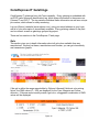
1
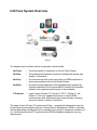
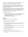
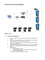
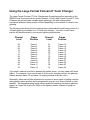
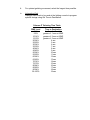
Large Format Coloram IT User Manual 816090 - Large Format Coloram IT 85000 - Large Format Aquaram IT 816080 - 8 Light Large Format Coloram IT Large Format Coloram IT software version: V2.1 Manual issue date: Janduray 21, 2009 CONTENTS Declaration of Conformity .......................................... 3 Safety Information...................................................... 4 Introduction ................................................................ 5 InfoTrace System Overview ....................................... 6 InfoTrace Connection Diagram .................................. 9 Quick Start ................................................................. 9 Using The Coloram IT Color Changer...................... 10 Coloram IT System Components ............................. 11 Color Changer......................................................11 Gelstring...............................................................11 Power Supply.......................................................11 Cables..................................................................12 Coloram IT Menus ................................................... 15 Alerts/Error Messages..........................................17 DMX Address.......................................................19 Settings................................................................20 Sensor Info...........................................................21 Self Test (Demo)..................................................23 History..................................................................23 Reset Defaults.....................................................25 Head-Feet Restrictions ............................................ 25 Replacing a Gelstring............................................... 26 Equipment Compatibility .......................................... 27 sColoram IT Products and Standard Environments . 28 Warranty Information ............................................... 29 ColorExpress IT Gelstrings ...................................... 30 2 3 Safety Notice SAVE THESE INSTRUCTIONS READ AND FOLLOW ALL INSTRUCTIONS This manual gives step-by-step instructions for preparation, setup and operation of the Coloram IT Color Changer. There is a potential risk of injury to persons if the product is not used as instructed. The Coloram IT is not intended for residential use. WARNING: When using electrical appliances, use basic precautions, including: Read this manual before connecting power. Use supervision around children. Do not touch moving parts. Only use attachments recommended or sold by Wybron. Use in a dry location only. Replace only with same type and rating of fuse. For questions, contact Wybron at 1-800-624-0146. Product Modification Warning Wybron, Inc. products are designed and manufactured to meet the requirements of United States and International Safety standards. Modifications to the products could affect safety and render the product noncompliant to relevant safety standards. 4 Introduction The Large Format Coloram IT system includes a scrolling color changer and PS Power Supply, that uses Remote Device Management (RDM) bi-directional communications protocol, in a range of models and offers an ease of setup and use. The Large Format Coloram IT system is part of the InfoTrace system that represents a new way of managing a lighting installation. The Large Format Coloram IT system, with its variable color capacity, RDM features and DMX compatibility affords the designer economy and versatility, The DMX512 control signal from the lighting console is connected through the InfoGate Gateway and dimmers to the PS Power Supply, and can continue on to additional PS Power Supplies or other DMX-controlled devices. The power supply sends power, DMX control signal and RDM information to the color changers on a single cable, eliminating the need for a separate power cable for the color changers. Large Format Coloram IT color changers are 100% compatible with all members of the Coloram IT family including CXI IT color changers, PS Power Supplies, the Eclipse IT Dowser and Eclipse II IT Dowser. You can also daisy chain Large Format Coloram IT color changers with other Coloram IT equipment. This manual gives step-by-step instructions for preparation, setup and operation of the Large Format Coloram IT Color Changer as part of the InfoTrace system. Caution: The Large Format Coloram IT System is not compatible with Coloram II (RAM) System. Do not connect Large Format Coloram IT Color Changers to Coloram II (RAM) Power Supplies. Do not connect Coloram II color changers to PS Power Supplies. Damage from such action will not be covered by the product warranties. 5 InfoTrace System Overview Figure 1 The diagram above outlines the key components, which include: InfoTrace – The entire system is referred to as the InfoTrace System InfoGate – The software and hardware required to facilitate the transfer and display of information InfoChip – A conversion chip that can be used with non-RDM equipment to allow communication with the InfoGate Software InfoStore – An Internet based application that aggregates data captured by InfoGate and allows for the accumulation of historical information related to the equipment performance in the installation IT Products – Large Format Coloram IT, Coloram IT,CXI IT, Eclipse IT, and Eclipse II IT all have updated electronics to support RDM communication plus additional product improvements, including sensors to detect a variety of conditions. The heart of the InfoTrace (IT) system is InfoGate — specialized software that uses the bi-directional communications protocol, Remote Device Management (RDM), to facilitate remote addressing and diagnostics for potentially every piece of equipment mounted on a rig. InfoGate works with all IT products and all RDM-compatible equipment from any manufacturer. 6 In addition, any non-RDM equipment can be upgraded with the installation of an InfoChip. Because InfoGate can work with any equipment, the setup, unit testing, and troubleshooting for an entire rig can be coordinated from a single laptop. Wybron's IT equipment (Coloram IT, CXI IT, Eclipse IT, and Eclipse II IT) is equipped with a series of sensors that can relay a wealth of information to InfoGate. These sensors can detect everything from light, voltage, current, to fan speed and even gelstring frame color information. So while RDM equipment will allow identification and remote addressing, IT equipment can give more specific status information and warn of potential problems, possibly averting failures in the middle of a show. If the status of a device indicates any problem, InfoGate displays an alert with the nature of the problem and the exact location. Troubleshooting is now done in a fraction of the time. InfoTrace provides the ability to: • • • • • Automate the setup of DMX addresses – no more manual setting of DIP switches Proactively check the condition of equipment before, during and after a show Track lamp duty cycles to predict lamp failures before they happen Predict maintenance on equipment Predict gel replacement prior to degradation Sensors Large Format Coloram IT, CXI IT, Eclipse IT and Eclipse II IT: • Aperture Light Sensor: Detects if the fixture's lamp is on. • Voltage Sensor: Reports the head voltage level. • Pass Through Current Sensor: Measures the amount of current that passes through the XLR connector wiring harness; assists in automatically setting up the rig in conjunction with InfoGate. • Unit Current Sensor: Measures the amount of current that a unit is consuming, which can be an indicator of motor health. • Timers: Keep track of how many hours the unit has been in operation in it’s lifetime and also since its last maintenance cycle. • Fan RPM Sensor: RPM sensor on fan. • Self Test Mode: Moves the gelstring without a DMX input command. • Reverse Polarity Protection: Auto shutdown if scroller is plugged into a Coloram II power supply. 7 Additional Sensors Large Format Coloram IT and CXI IT only: • Gel Color Reader: Reads digital information off of the gelstring, including gelstring frame color information. • Gel Wear Counter: Tracks how much the gelstring has moved and alerts the user when a gelstring needs to be replaced. • Gel Temperature Sensor: Approximates and reports the temperature of the gel. • "Gelstring is broken" Sensor: Detects if the gelstring is broken after gelstring initialization. • Motor Shutdown if Gelstring is Broken: Automatically shuts down the motor if the gelstring breaks or comes loose from a roller. Alert Warnings include: • Fan Stopped • High Motor Current • Fan Off and Lamp On • Unit Cleaning Period Reached • Gelstring Initializaion Fail • Low Voltage Alert • Low Voltage Unit Shutdown • Gelstring out of Position, Unit Shutdown (Coloram IT and CXI IT only) • Gelstring Replacement Period Reached (Coloram IT and CXI IT only) 8 InfoTrace Connection Diagram LF Coloram IT Figure 2 Quick Start 1. Connect the Equipment A. B. C. D. E. 9 Attach the Large Format Coloram IT Color Changer to a powered light fixture. Connect the Large Format Coloram IT Color Changer to the PS Power Supply using the 4-pin Wybron Power/Data Cable. Connect the PS Power Supply to non-dimmed 100-240 VAC, 50/60Hz power and to a DMX source. Connect dimmers that have InfoChip installed, to the InfoGate hardware and software. Please refer to the InfoGate and InfoChip manuals for details. Using InfoGate: i. Initiate “Perform Discovery” ii. In the DMX Map, drag and drop the DMX address for the color changer to DMX address 1. Please refer to the InfoGate manual for details. Using the Large Format Coloram IT Color Changer The Large Format Coloram IT Color Changer sets its gelstring position according to the DMX512 level it receives from the control console. As all Large Format Coloram IT Color Changers will accommodate variable length gelstrings, the level settings which correspond with each frame position will vary depending on the number of frames in the gelstring. The following chart shows the level settings that correspond with each frame position if a 24 frame gelstring is installed on a 7.5-inch color changer. The color of each frame position will be determined by your custom gelstring specification. Channel Level Frame Position Channel Level Frame Position 00 04 09 12 17 21 25 29 34 38 42 47 Frame 1 Frame 2 Frame 3 Frame 4 Frame 5 Frame 6 Frame 7 Frame 8 Frame 9 Frame 10 Frame 11 Frame 12 51 55 59 64 69 73 78 82 87 91 96 FL Frame 13 Frame 14 Frame 15 Frame 16 Frame 17 Frame 18 Frame 19 Frame 20 Frame 21 Frame 22 Frame 23 Frame 24 If you send a channel level that is between the values shown, you can create split frame effects. For example, if you send a level of 49, the color changer positions the gelstring halfway between frame 12 and frame 13 creating a blend of the two colors. Alternately, when the InfoGate information is exported to some types of lighting consoles, each gelstring frame position can be programmed as a gel color, frame number or other identifier. The desired gelstring frame is then recalled by selecting the desired gelstring frame (i.e. Frame 09) or gel color (R68) on the lighting console, instead of typing in a DMX level. 10 Large Format Coloram IT System Components Color Changers All Large Format Coloram IT Color Changers use gelstrings which can vary in length. The color changers set the position of the gelstring as determined by the DMX level. The color changers are powered by 24 volts DC which also comes from the power supply. The control signal, RDM data and DC power are all supplied in one cable connecting the color changers to the power supply. Note: Please refer to the Specifications section of this manual for the maximum number of gelstring frames each color changer will hold. Gelstring The gelstring is a series of precisely cut, colored gel frames joined together, side by side, to create a sequence of colors. Two additional gels at each end of the gelstring are called the leader and the trailer. The leader and the trailer allow for proper attachment to the rollers. The gelstring has foil tags near each end which are necessary for the color changer's automatic calibration to the length of that particular gelstring. Traile r Frame 32 Frame 31 Long foil tag Frame 2 Short foil tag Frame 1 Leade r RFID tag Figure 3 The Large Format Coloram IT gelstring also has a radio frequency identification (RFID) tag which identifies the sequence of gels on the gelstring (as part of the InfoTrace setup process), and also assists in ordering additional gelstrings. Please refer to the ColorExpress IT section of this manual for information on how to create and order gelstrings online. Power Supply The PS Power Supply sends the DMX512 signal level from the lighting console to each color changer, along with 24 volts DC. RDM information is sent from the Large Format Coloram IT Color Changer to the InfoGate software installed on a Mac or PC. 11 Cables Power/Data cable The 4-pin Power/Data Cable connects the PS Power Supply outputs to the Large Format Coloram IT Color Changers and provides them with power and control signal. The Power/Data cable uses 4-pin XLR connectors on either end and consists of two 14 AWG conductors and a 22 AWG twisted, shielded pair. The shells of the two XLR connectors are not electrically connected -- this prevents high power currents from flowing from chassis to chassis of the Coloram IT equipment. The twisted pair shield is connected only at the male XLR connector end. This is the standard Wybron Power/Data Cable. XLR Pin # 1 2 3 4 Wire Color White Green Red Black Function Ground Data Data + 24 Volts DC Size 14 AWG 22 AWG 22 AWG 14 AWG Note: The cable used in the Large Format Coloram IT System is the same cable which is used in the Coloram II and Forerunner Systems and may be referred to as Coloram IT, Coloram II or Forerunner cable. DMX512 control cable The DMX control cable from the lighting board to the InfoGate Gateway, dimmers and power supply is a five conductor cable with 5-pin XLR connectors on each end. The wiring pin out is specified by the USITT DMX512 / 1990 standard. XLR Pin # 1 2 3 4 5 Function Common Data Data + Talkback Talkback + 12 Main LCD Menu [Alerts Menu] [DMX Status] DMX Address: 512 Settings Sensor Info History Reset Defaults > Large Format COLORAM (IT) > > > > Graphical Menu Tree Alerts Menu This menu only displays when there is an active alert on the unit. DMX Status Displays status of incoming DMX signal. Examples: “No DMX Data” or “DMX Signal OK” Multiple Alerts Example GEL ALERT > Single Alert Example GEL ALERT FAN ALERT GEL STRING OUT OF POSITION - UNIT SHUT DOWN > Reset all Alerts? No/Yes Reset this Alert? No/Yes DMX Address Displays current DMX Address that can be selected and modified, using unit buttons. Note: The unit will remember its DMX Address when unplugged. Settings DMX Addresses Fan Speed Gel Move Speed > > > Note: The unit only supports one secondary address at a time. You can have Fan Speed on a remote channel or Time To Destination (Time/Dest) on a remote channel but not both remotely controlled at the same time. DMX Addresses Device addresses can be modified from this screen. Scroller Address Fan Speed Addr Time/Dest Addr 1 2 3 Fan Speed Options: High - default Low Remote - control remotely via assigned DMX channel Fan Speed FAN high SPEED Gel Move Speed Options: High - default Low Time/Dest - control remotely via assigned DMX channel Gel Move Speed high GEL TTD info MOVE SPEED > TTD info Time/Dest Addr Information Continued next 13 page… 3 > Information Chart of information regarding time to destination remote settings. No changes can be made from this screen. TIME TO DEST INFO ONLY 95-100%: Hi 90-94%: Low 85-89%: 80 sec 80-84%: 70 sec 75-79%: 60 sec 70-74%: 50 sec 65-69%: 40 sec 60-64%: 35 sec 55-59%: 30 sec 50-54%: 25 sec 45-49%: 20 sec 40-44%: 15 sec 35-39%: 10 sec 30-34%: 9 sec 25-29%: 8 sec 20-24%: 7 sec 15-19%: 6 sec 10-14%: 5 sec 5-9%: 4 sec 0-4%: ASAP Main LCD Menu [Alerts Menu] [DMX Status] DMX Address: 512 Settings Sensor Info History Reset Defaults Gel Wear Gauge > New GEL WEAR GAUGE > > > > Replace Note: This gauge is maintained in the RFID Gel String Tag. Not on the device. Frame # vs. Color Sensor Info Gel String Info Voltage Fan RPM > > > GEL FRAME COLOR #1 #2 #3 #4 #5 #6 W0 G1 L2 L1 G8 R1 Gel String Info Gel Wear Gauge Frame # vs. Color String Description String Description > > > ColorExpress GEL String for STR. Midsummer DESC. Dream 9/2006 Voltage VOLTAGE Now = 23.8V(15V min) High = 23.8V(24V max) Low = 23.7V(15V min) Reset Hi & Low? No/Yes Cleaning Info Gel String History Fan RPM Fan RPM OK? Yes Tot Time: 12hr Tot Moves: 549 Tot Dist: 0 met Avg Move: 0 cm Avg Vel: 168 cm/sec Max at frame: 22400 Reset > Like New Needs Cleaning Reset History Gel String History Operating Hours Host Light Lamp Reset Defaults RESET FACTORY DEFAULT SETTINGS? SINCE CLEAN RESET: 287 HR No/Yes > > > Operating Hours Cleaning Info > Maintenance Info > Lifetime Hours is 287 Host Light Lamp HOST LAMP HOURS: 16 HR Reset > New 500 hrs Reset RESET No/Yes HOST LIGHT LAMP HOURS GAUGE? RESET No/Yes CLEANING HOURS GAUGE? Maintenance Info SINCE MAINT RESET: 287 HR Reset > Like New Needs Maint. Reset RESET No/Yes MAINTEANCE HOURS GAUGE? 14 MENU DETAILS 1. Use the π and θ buttons to scroll through selections on Large Format Coloram IT display. 2. Press SELECT to activate that selection. Figure 5 The π and θ buttons are also used to navigate to further levels within the display. For example, to select “Scroller Address”: 1. 2. 3. 4. 5. 6. Use the π and θ buttons to move to the selection box to “Settings”. Press SELECT to select “Settings”. Use the π and θ buttons to move to the selection box to “DMX Addresses”. Press SELECT to select “DMX Addresses”. Use the π and θ buttons to move to the selection box to “Scroller Address”. Press SELECT to select “Scroller Address”. Alerts / Error Messages The following is an explanation of alerts and error messages that are displayed locally on the color changer. To read alert messages: 1. 2. 3. 4. When “SENSOR ALERT” is displayed, press SELECT. As an example: “VOLTAGE ALERT” indicates a voltage problem. Press SELECT to access more information on the Voltage Alert. For example: “WARNING – VOLTAGE DROPPED BELOW 15V” VOLTAGE ALERTS • 15 “WARNING – VOLTAGE DROPPED BELOW 15V” Operating voltage has dropped below the minimum operating requirement of 15 volts. The cable between the Large Format Coloram IT and the PS Power Supply may be too long. • “VOLTAGE DROPPED BELOW 13V UNIT SHUTDOWN” Unit has automatically shut down because operating voltage has dropped below 13 volts for more than one second. The voltage typically drops this low if the Large Format Coloram IT cable is too long — the head-feet limit has been exceeded. The Large Format Coloram IT cable must be shortened or the number of Large Format Coloram IT scrollers must be reduced to solve this problem. GEL ALERTS 1. “GELSTRING OUT OF POSITION — UNIT SHUTDOWN” Scroller motor automatically shuts down if gelstring is not at its programmed frame position or a roller is stuck. 2. “GELSTRING DID NOT INIT PROPERLY” Gelstring did not initialize properly. Please check that gelstring is properly installed. 3. “GELSTRING IS BROKEN — UNIT SHUTDOWN” Scroller motor automatically shuts down if gelstring has broken or come loose from a roller. Gelstring needs to be replaced or reinstalled. MOTOR ALERT 1. “MOTOR IS OPERATING AT A HI CURRENT LEVEL” High current level at the scroller motor may indicate an ususually high level of friction at the motor. Please check scroller motor for possible maintenance or replacement. FAN ALERT 1. “FAN IS OFF WHILE THE LAMP IS ON” The color changer may overheat or premature fading of the gelstring colors may occur when the scroller fan is off while the fixture lamp is on. 16 2. “FAN IS NOT OPERATING PROPERLY” Check fan for possible maintenance. RFID ALERTS 1. “RFID TAG — COMMUNICATION FAILURE” A. Communication could not be established with the RFID tag. B. Press SELECT for more detailed information: i. “COULD NOT WAKE THE RFID TAG” RFID wake command did not finish. ii. “COULD NOT READ THE RFID TAG” Coloram IT had a communication failure when trying to read the RFID tag. iii. “COULD NOT WRITE THE RFID TAG” Coloram IT had a communication failure when trying to write to the RFID tag. RESET ALERT Clears existing alert from display screen when you press SELECT, unless the problem still currently exists. MULTIPLE ALERTS 1. Press SELECT to read the first alert. 2. Press SELECT to read the details of the first alert. 3. Press BACK to view the second alert. 4. Press SELECT to view details of the second alert. 5. Press BACK to check if there any additional alerts, repeat Steps 4 and 5 until all alerts have been read. 6. Once all alerts have been read, use the d key to move the selection box to the “RESET ALL ALERTS” command. 7. Press SELECT to clear all alerts, except for those that currently exist as problems. 17 DMX Address 1. 2. Use the π and θ buttons to select the desired Coloram IT DMX address. Press SELECT to activate the displayed Coloram IT DMX address. Settings DMX ADDRESSES Scroller Addr (Scroller Address) A. Use the π and θ buttons to select the desired Coloram IT DMX address. B. Press SELECT to activate the desired Large Format Coloram IT DMX address. Fan Speed Addr (Fan Speed Address) A. Selecting a DMX address for Fan Speed Address also automatically sets Fan Speed to “REMOTE” (see “Fan Speed” below). B. Use the π and θ buttons to select the desired DMX address. C. Press SELECT to activate the desired DMX address. Time/Dest Addr (Time to Destination Address) If this function is enabled, this feature controls the time it takes to arrive at the destination gelstring position after the new destination command is sent. A. Use the π and θ buttons to select the desired DMX address. B. Press SELECT to activate the desired DMX address. FAN SPEED 1. Use the π and θ buttons to select High (normal setting), Low or Remote. A. REMOTE assigns Fan Speed control to the lighting console where: 51% to 100% = Fan at High (normal) setting 0% to 50% (except 8%) = Fan at Low setting 8% = Off GEL MOVE SPEED 1. Use the π and θ buttons to select High, Low or Time/Dest (Time to Destination). 2. Press SELECT to activate the desired setting. TTD Info (Time to Destination information) A. Gel Time to Destination DMX Address — use the π and θ buttons to select the desired DMX address. i. If this function is enabled, this feature controls the time it takse to arrive at the destination gelstring position after the new destination command is sent. ii. The DMX address for this feature can also be set at the alternate display “DMX Address: DMX Addresses: Time/Dest Addr”. 18 iii. For quietest gelstring movement, select the longest time possible. iv. Information Only Displays DMX levels to be used at the lighting console to program specific timings using Gel Time to Destination. Coloram IT Gelstring Time Table DMX Level 0-4% 5-9% 10-14% 15-19% 20-24% 25-29% 30-34% 35-39% 40-44% 45-49% 50-54% 55-59% 60-64% 65-69% 70-74% 75-79% 80-84% 85-89% 90-94% 95-100% 19 Time to Destination As Soon As Possible greater of: 1 sec or ASAP greater of: 2 sec or ASAP greater of: 3 sec or ASAP 4 sec 5 sec 6 sec 7 sec 8 sec 9 sec 10 sec 11 sec 12 sec 13 sec 14 sec 15 sec 16 sec 17 sec 18 sec 19 sec Sensor Info GELSTRING INFO Gel Wear Gauge Press SELECT to display the gauge that indicates how gelstring currently rates between “New” and “Replace”. Figure 6 Frame # vs. Color Lists each frame number and associated gel color. Use the π and θ buttons to scroll through list. For example: Frame 3 L110 Frame 4 R02 Frame 5 R33 Frame 6 R01 String Description Press SELECT to display the gelstring description created by the user when the gelstring was ordered. The order information is also imbedded on the gelstring RFID tag: ABC Co. Order 53968 Woman in Black 22 Jan. 2005 GELSTRING INTACT? Press SELECT to display answer to this question (Yes or No). VOLTAGE 1. Displays present voltage, highest and lowest voltages measured, along with normal minimum and maximum acceptable voltages. Reset Hi & Low: A. Use the π and θ buttons to select Yes. B. Press SELECT to activate Reset Hi & Low. SCROLLER CURRENT 1. Displays present current, highest and lowest current measured, along with normal minimum and maximum acceptable current. A. The amount of current used by a scroller is a measure of scroller friction 20 B. and an indicator of the general health of the unit. An increase in the amount of current needed for a scroller to operate may signal that is motor is going bad. Reset Hi & Low: A. Use the π and θ buttons to select Yes. B. Press SELECT to activate Reset Hi & Low. PASS THRU CURRENT 1. Displays present pass through current, highest and lowest current measured, along with normal minimum and maximum acceptable pass through current. A. Used in automatically sequencing through RDM enabled units on the lighting rig during InfoGate setup procedures. Reset Hi & Low: A. Use the π and θ buttons to select Yes. B. Press SELECT to activate Reset Hi & Low. FAN RPM Press SELECT to display answer to the question “IS FAN RPM OK?” (Yes or No). Self Test (Demo) MOVE / STOP 1. Use the π and θ buttons to select “Move” or “Stop” gelstring commands. 2. Press SELECT to activate selected command. 3. Present current and voltage information is also displayed, along with maximum acceptable current and minimum acceptable voltage. History GELSTRING HISTORY 1. Use the π and θ buttons to scroll through the data. All gelstring history reflects lifetime use of that gelstring, whether the gelstring has been moved from one scroller to another or remained with the same scroller throughout its lifetime. Total Time (in hours) The total number of hours that the gelstring has been in use over its entire lifetime. Total Moves The total number of times that the gelstring has scrolled from one gel 21 frame to another. Total Distance (in meters) The total distance that the gelstring has scrolled. Average Move (in centimeters) The average distance that the gelstring moves per command. Average Velocity (in centimeters per second) The average velocity at which the gelstring moves. Max at Frame: The frame count is the number of times that each frame of the gelstring has been in the aperture of the Large Format Coloram IT. This information is stored in the InfoTrace system and the RFID tag on the gelstring. The “Max at Frame” number is the largest number of all the frame counts. Example: The color changer has been to following frames: Frame 1 Frame 2 Frame 3 15 times 11 times 37 times The Max at Frame number displayed is 37. OPERATING HOURS Cleaning Info A. Lifetime operating hours is shown at the bottom of the first display, which is the total number of hours the scroller has been in use over its lifetime. This counter is never reset. B. Press SELECT to display the gauge that indicates how the color changer currently rates between “Like New” and “Needs Cleaning”. Figure 7 22 Cleaning means cleaning dust out of the vent slots, off the printed circuit board, off the internal components and cleaning the inside surfaces of the tag sensor. C. The display also shows the number of hours since the last cleaning of the color changer. Reset the Hours function after each cleaning: Reset Hours i. Press SELECT to select the Reset Hours function. ii. Use the π and θ buttons to select Yes on the “Reset Cleaning Hours Gauge?” iii. Press SELECT to activate Reset Cleaning Hours Gauge. Maintenance Info A. Lifetime operating hours is shown at the bottom of the first display, which is the total number of hours the scroller has been in use over its lifetime. This counter is never reset. B. Press SELECT to display the gauge that indicates how the color changer rates between “Like New” and “Needs Maintenance”. Figure 8 Maintenance means replacing a failed part on the color changer. C. The display also shows the number of hours since the last maintenance on the color changer. Reset the Hours function after each maintenance cycle: Reset Hours i. Press SELECT to select the Reset Hours function. ii. Use the π and θ buttons to select Yes on the “Reset Maintenance Hours Gauge?” iii. Press SELECT to activate Reset Maintenance Hours Gauge. Host Light Lamp A. Press SELECT to display the gauge that indicates the number of hours that the lighting fixture has been on since its lamp was installed. Reset the Hours function after each relamping. 23 Figure 9 Reset Hours i. Press SELECT to select the Reset function. ii. Use the π and θ buttons to select Yes on the “Reset Host Light Lamp Hours Gauge?” iii. Press SELECT to activate Reset Host Light Lamp Hours Gauge. Reset Defaults 1. 2. 3. Press SELECT to select “Reset Defaults”. Use the π and θ buttons to select Yes to Reset Defaults. Press SELECT to activate Reset Defaults: Scroller address is 1 Fan address is 2 Time to Destination address is 3 Fan speed is High Gel speed is High Head-Feet Restrictions The HEAD-FEET parameter is a method of accounting for the voltage drop in the power/signal cable caused by the current drawn by each color changer. To help understand this issue, think of it as water pressure (voltage) in a hose (cable) where you have multiple water sprinkler heads (color changers). If the hose (cable) is too long or you have too many sprinkler heads (color changers), the water pressure (voltage) will be too low. HEAD-FEET is defined as "the sum of cable lengths from each color changer to a single power supply output". 24 Head-Feet Example: 1 2 3 4 Coloram IT Color Changers PS Power Supply 100’ 20’ 20’ Figure 8 20’ Power/Data Cable Figure 10 The length of cable from the Power Supply to: 1st Coloram 100' 2nd Coloram 120' 3rd Coloram 140' 4th Coloram 160' 520 "head feet" The maximum HEAD-FEET for each of the Coloram IT Color Changers is as follows: Large Format Coloram IT Large Format Aquram Coloram IT 1000 head feet 1000 head feet If a daisy chain consists of different models, use the model with the smallest amount of "head feet" for the calculation. Mounting and Installation Accessories The components of your Large Format Coloram IT System may require the installation of additional mounting accessories or the replacement of others. Some of these accessories are supplied, such as the power supply hanger brackets and your choice of one color changer mounting plate. Other accessories, such as the power supply rack mount kit and additional mounting plates, may need to be purchased separately. The following sections describe the procedures for installation and replacement of some of these accessories. 25 Replacing a Gelstring At some point in time you may find that you need to replace the gelstring in your color changer, either because the old one wears out or because you want a different selection of colors. With all the Large Format Coloram IT Color Changers this is quick and easy. Caution: Operating the Large Format Coloram IT Color Changers with damaged gelstrings will damage the color changers. Replace the gelstrings before damage occurs. Note: If a frame in the gelstring becomes damaged, do not remove the frame and splice the gelstring. Replace the gelstring. Gelstrings may be ordered online from Color ExpressIT at www.wybron.com. See the ColorExpress IT section at the end of this manual for details. Install the new gelstring Note: Use good quality gaffer's tape to attach the gelstrings to the rollers. Do not use duct tape or masking tape. Be sure the roller is clean. The tape should be 2/3 of the roller length and apply the tape “lengthwise” on the roller. Figure 14 1. Put a strip of gaffer's tape on the edge of the gelstring trailer. Holding the trailer, let the rest of the roll hang off the right side of the color changer. 2. Center the edge of the trailer between the two flanges of the left roller as shown to the left. Tape the trailer along the top of the roller as shown. 3. Roll the gelstring onto the left roller until the end of the leader is directly above the right roller. 4. Put a strip of gaffer's tape on the gelstring leader. 5. While holding the end of the gelstring, turn the right roller toward the left roller. The sticker at the bottom end of the roller has a black line on it to help you judge the number of turns. 6. Tape the gelstring to the right (spring) 26 Equipment Compatibility The following is a chart of compatibility and capacity of the various models of PS Power Supply and their companion IT devices. 27 Non-RDM Equipment and InfoTrace A lighting rig can use any combination of non-IT, non RDM, non-InfoChip equipment, along with IT equipment. The non-IT equipment will work the old-fashioned way (hand addressing, no status reporting or other features). The RDM protocol allows configuration, status monitoring and management of RDM devices in such a way that does not disturb the normal operation of the DMX devices that do not recognize the RDM protocol. Coloram Large Format IT and Standard (non-IT) Environments The Large Format Coloram IT family of products (Coloram IT, CXI IT, Eclipse IT and Eclipse II IT, which all must be connected to PS Power Supplies) will work in any standard environment that does not use InfoGate. The Coloram IT System cable 7042-3............................................... 3' power/signal cable 7042-5............................................... 5' power/signal cable 7042-10............................................. 10' power/signal cable 7042-15............................................. 15' power/signal cable 7042-25............................................. 25' power/signal cable 7042-50............................................. 50' power/signal cable 7042-75............................................. 75' power/signal cable 7042-100........................................... 100' power/signal cable 28 Warranty Information WYBRON, INC. warrants to the original owner or retail customer that for a period of one year from date of delivery of a portable system or energization of a permanently installed system (up to a maximum of 18 months from delivery) its products will be free from defects in materials and workmanship under normal use and service. Warranty does not cover any product or part of a product subject to accident, negligence, alteration, abuse, misuse or any accessories or parts not supplied by WYBRON, INC. Warranty does not cover "consumable" parts such as fuses, lamps, or color media. WYBRON, INC.'s warranty does not extend to items not manufactured by us. Freight terms on warranty repairs are FOB WYBRON, INC. factory or designated repair facility. Collect shipments or freight allowances will not be accepted. WYBRON, INC.'s sole responsibility under this warranty shall be to repair or replace at WYBRON, INC.'s option such parts as shall be determined to be defected on WYBRON, INC.'s inspection. WYBRON, INC. will not assume any responsibility for any labor expended or materials used to repair any equipment without WYBRON, INC.'s prior written authorization. WYBRON, INC. shall not be responsible for any incidental, general or consequential damages to property, damages for loss of use, time, profits or income, or any other charges. The owner's obligations during the warranty period under this warranty are to notify WYBRON, INC. at WYBRON, INC.'s address within one week of any suspected defect, and return the goods prepaid to WYBRON, INC. at their factory or authorized service center. This warranty is contingent on the customer's full and timely compliance with the terms of payment set forth in said purchase order. This warranty is expressly in lieu of any and all other warranties expressed or implied including the warranties of merchantability and fitness for a particular purpose and of other obligations and liabilities on our part. The owner acknowledges that no other representations were made to him or relied upon him with respect to the quality and function of the goods sold. This written warranty is intended as a complete and exclusive statement of the terms thereof. Prior dealings or trade usage shall not be relevant to modify, explain or vary this warranty. Acceptance of, or acquiescing in, a course of performance under this warranty shall not modify the meaning of this agreement even though either party has knowledge of the performance and a chance to object. 29 ColorExpress IT Gelstrings ColorExpress IT gelstrings have InfoTrace capability. Every gelstring is embedded with an RFID (radio frequency identification) tag, which relays information to the sensors on Coloram IT and CXI IT. The tag contains individual frame information as well as a unique job number, which allows for easy reordering. Log into Wybron’s website (www.wybron.com), using your email address as your login, and all of your information is immediately available. Every gelstring ordered in the past can be viewed, as well as gelstrings grouped by project. There are four sections in the ColorExpress IT web page: Gels This section gives you in depth information about all gel colors available from any manufacturer. Beyond just name, manufacturer and number, you can get chromaticity and transmission graphs. Figure 15 If the gel is within the range reproducible by Wybron’s NexeraLX dichroic color mixing fixture, the DMX values (0 – 255) are displayed for the Cyan, Magenta and Yellow dichroics. If Nexera cannot exactly match a gel color, a suggested combination of DMX values will be displayed. Figure 16 30 Click on the transmission graph to enlarge the graph. Figure 17 Clicking on “Similar Colors” displays gels similar to the selected G315. Figure 18 Clicking on “CIE Complement” displays gels that are the complement or opposite of G315. Figure 19 31 To release the display of “Similar Colors” or “CIE Complement”, click on any gel color displayed on the screen. Colors can also be searched by name (“purple” or “congo”), gel number, and brand. Figure 20 Gelstrings This is where you build new gelstrings, as well as view all the past gelstrings that you have created on ColorExpress IT. When new gelstrings are created, you assign them a name (“Finale” for example). This makes it easy to locate favorite gelstrings from past shows. A simple double-click on any gel color in the palette makes it easy to create new gelstrings. Rearrange gels in your gelstring by dragging and dropping them in any order desired (Safari and Firefox only). 32 Figure 21 To delete a gel from the gelstring, double click on the selected color in the gelstring. Previous gelstrings that you have created are also stored on the Gelstring page. Figure 22 By clicking on “Cheat Sheet” on the far right hand side of the screen, you can also print out color coded cheat sheets showing frame number, gel name, gel number, and DMX value. 33 Figure 23 The selections on the Gelstring screen allow you to do the following: Cheat Sheet Prints out a color coded cheat sheet of the selected gelstring Delete Deletes the selected gelstring Clone Copies the selected gelstring as a new gelstring, ready for edits Modify Allows the user to edit the selected gelstring Return to Main Return to the Main Page of ColorExpress IT New Gelstring Create a new gelstring Sets of CXI gelstrings (Gelstrings 1 and 2) may also be ordered online at ColorExpress IT. Please see the “Order” section below for details. Projects Create a Project Projects are an easy way to associate certain gelstrings with their use. Click on “Create New Project” to start a new project file: Figure 24 34 This opens a new screen ready to accept project and gelstring information. Figure 25 Double click on “Untitled Project” to the right of colon to edit the Project Name field. Enter the project name in the dialogue box provided and click “OK”. Figure 26 Under Contact, double click on “Unknown” to fill in that field, and similarly for the Notes line, double click on “Project Notes” to add any additional information. Multiple gelstrings on Project A project can involve multiple gelstrings. When a new project is created, add existing gelstrings or build new ones to associate with that project. Then choose a scroller size. For example, the “Back Diagonals” gelstring will be used on 7 inch Coloram II’s. All of this information is saved in the “Opera in Mali” project. 35 Figure 27 The functions on this show specific (“Opera in Mali”) Projects page include: Download Cheat Sheet Creates a PDF file of the selected gelstring cheat sheet (see the color coded Cheat Sheet example earlier in this section). Email Cheat Sheet E-mail a cheat sheet version of the selected gelstring to one or more e-mail addresses. Modify Modify the selected gelstring in terms of: Gelstring Device Quantity Replace the selected gelstring with another existing gelstring Change the type of scroller associated with the selected gelstring Change the number of gelstrings to order Add existing gelstring to project Using the Gelstring pull down menu, allows the user to select from any existing gelstrings. Add new gelstring to project Takes the user back to the Gelstrings page, where once a new gelstring is created and saved, it is automatically added to the open Projects page. 36 Back to project list Returns to the list of all projects. Ordering Returning to the project list displays all projects created by the user. Figure 28 The functions available on this page include: Detail Returns user to Projects page for the specific show selected (see Figure 22). Delete Deletes the selected project. Order Project Displays the order page, along with the gelstring details at the bottom of the screen. Additional gelstrings that are part of the project can be viewed by using the scroll bar at the bottom right corner of the screen. Figure 29 Fill in the requisite information and click “Place Order” to complete the transaction. 37 E-Mail Project for Ordering For users who need to get approval to place a gelstring order, click on “Email project for ordering” to display the window below. Figure 30 Fill in the requisite e-mail address and click “Send Email” to send the following message. In the example below, the user is signed in as “Guest”. Figure 31 Orders This is where you can view all your past gelstring orders. Modify Your Account Click on “Modify Your Account”, which appears at the top right corner of each screen once you have sign in. Edit information as needed. 38 Figure 32 39