1
LDS1000
Controller for
Laser Diode Sensors
USER’S MANUAL
For Motion, Think Newport
LDS1000
Controller for Laser Diode Sensors
Warranty
Newport Corporation warrants this product to be free from defects in material and workmanship for a period of 1 year from the date of shipment. If
found to be defective during the warranty period, the product will either be
repaired or replaced at Newport’s discretion.
To exercise this warranty, write or call your local Newport representative,
or contact Newport headquarters in Irvine, California. You will be given
prompt assistance and return instructions. Send the instrument, transportation prepaid, to the indicated service facility. Repairs will be made
and the instrument returned, transportation prepaid. Repaired products
are warranted for the balance of the original warranty period, or at least 90
days.
Limitation of Warranty
This warranty does not apply to defects resulting from modification or misuse of any product or part.
CAUTION
CAUTION
Please return equipment in
the original (or equivalent)
packing.
You will be responsible for
damage incurred from inadequate packaging if the
original packaging is not
used.
The warranty does not apply to defects resulting:
• from misuse
– Different use from that intended by NEWPORT.
– Use of a cable different to the one supplied by NEWPORT.
– Use or storage in environmental conditions other than those indicated.
– Poor maintenance of the equipment, in particular, scratches on the
front optic, excessive humidity, shocks to the body.
• from any modification to the product or one of its parts.
This warranty is in lieu of all other warranties, expressed or implied,
including any implied warranty of merchantability or fitness for a particular
use. Newport Corporation shall not be liable for any indirect, special, or
consequential damages.
No part of this manual may be reproduced or copied without the prior written approval of Newport Corporation.
This manual has been provided for information only and product specifications are subject to change without notice. Any changes will be reflected in
future printings.
EDH0170En1020 — 07/11
ii
LDS1000
Controller for Laser Diode Sensors
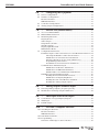
Table of Contents
Warranty..................................................................................................................ii
EC Declaration of Conformity .............................................................................vii
Definitions and Symbols.....................................................................................viii
Warnings and Cautions ..................................................................................viii
Warnings.................................................................................................................ix
1.0
—
Introduction................................................................................1
2.0
—
Description ..................................................................................1
2.1 Equipment ..................................................................................................2
2.2 Modes of Operation ..................................................................................2
Manual Mode..............................................................................................2
Remote Mode .............................................................................................3
Analog Mode ..............................................................................................3
2.3 Available Versions.....................................................................................3
Controller ...................................................................................................3
Sensor .........................................................................................................4
Accessories and Additional Equipment Kits .........................................4
2.4 Dimensions.................................................................................................4
3.0
—
Principle of Operation ..........................................................5
3.1 Laser Diode Sensors..................................................................................5
3.2 Electronic Controller ................................................................................5
4.0
—
Specification ...............................................................................6
4.1 General Characteristics ............................................................................6
LDS-Vector Optical Head ..........................................................................6
LDS1000 Controller....................................................................................6
Measurements ...........................................................................................6
Environment...............................................................................................7
RS-232-C and IEEE-488 Interfaces.............................................................7
Analog Outputs ..........................................................................................7
4.2 Validity of Specifications ..........................................................................7
Calibration..................................................................................................8
4.3 Noise Reduction ........................................................................................8
4.4 Offset Coefficient Adjustment..................................................................9
5.0
—
Starting the Equipment ......................................................10
5.1 Setting Up .................................................................................................10
Mounting...................................................................................................10
5.2 Electric Connections ...............................................................................10
5.3 Power Up ..................................................................................................11
Power Up Messages ................................................................................11
Alignment .................................................................................................11
iii
EDH0170En1020 — 07/11
LDS1000
Controller for Laser Diode Sensors
6.0
—
Configuring the Equipment ..............................................12
6.1 Sensor Configuration ..............................................................................12
6.2 Interface Configuration...........................................................................12
RS-232-C Interface....................................................................................12
IEEE-488 Interface ....................................................................................13
6.3 Controller Configuration ........................................................................13
6.4 Analog Output Configuration.................................................................14
7.0
— Off-Line Use (Manual Mode).............................................15
7.1 Access to Manual Mode..........................................................................15
7.2 Manual Mode Functions .........................................................................16
7.3 Measuring Functions...............................................................................17
Display Freeze..........................................................................................17
Offset Origin .............................................................................................17
Integration Constant ...............................................................................18
Graphic Display .......................................................................................18
Display Light Received ...........................................................................18
Maintenance Mode ..................................................................................19
7.4 Configuration Functions .........................................................................19
Parameter Input of the Current Sensor or the Memorized Sensors .19
Selecting the Number of the Current Sensor ............................19
Modification of Current Sensor Parameters .............................20
Display of Result in Arc-Seconds (LDS-Vector) ........................22
Programming a New Sensor ........................................................22
Visualization of Current Sensor Parameters.............................23
Communication Parameter Input ..........................................................23
Modification of RS-232-C Parameters.........................................24
Modification of IEEE-488 Parameters.........................................24
Default Values of Communication Parameters.........................25
LDS1000 Controller Parameter Input ....................................................25
Reading the Internal Software Version ......................................25
Modification of Display Brightness ............................................26
Reading the Size of the Memory Installed.................................26
Reading the Analog Output Option............................................26
8.0
—
Analog Output Parameter Input ....................................27
8.1 Selecting Analog Outputs (if option present)......................................27
8.2 Modification of Analog Output Parameters .........................................28
9.0
—
TRIG Input and PWOK Output........................................30
9.1 Conventions on Logical Inputs/Outputs ..............................................30
9.2 TRIG Input ................................................................................................31
9.3 PWOK Output...........................................................................................31
10.0 —
Use with a Computer Interface .......................................32
10.1 Checking the Interface ............................................................................32
RS-232-C Interface....................................................................................32
IEEE-488 Interface ....................................................................................33
10.2 LDS-TOOLS Software...............................................................................34
10.3 Programming............................................................................................35
Structure of Messages to the Controller ..............................................36
EDH0170En1020 — 07/11
iv
LDS1000
Controller for Laser Diode Sensors
10.4
10.5
10.6
10.7
10.8
Programming Conventions ....................................................................37
List of Commands....................................................................................38
Commands Listed by Category..............................................................38
System Management ....................................................................38
Reading Current Sensor Parameters..........................................38
Classical Acquisitions ..................................................................38
Dynamic Acquisitions ..................................................................38
Reading Logical Inputs/Outputs .................................................38
Commands Listed in Alphabetic Order ................................................39
Description of Commands......................................................................39
KI
Define the Integration Constant .................................................40
ML Return to Local Mode ..................................................................41
MR Set Interface Mode........................................................................42
MS Read Acquisition Status...............................................................43
RB Read TRIGG Input Status .............................................................44
RD Set Frozen Display Mode .............................................................44
RE
Set Active Display Mode ..............................................................45
RO Read PWOK Output Status ..........................................................45
RS
Reset System .................................................................................46
SP
Define Sample Period ...................................................................46
ST
Stop Work in Progress .................................................................47
TA Query Sensor Parameters ...........................................................48
TB
Error Description..........................................................................48
TE
Read Error Code ...........................................................................49
TK
Acquisition on External Trigger .................................................50
TM Immediate Acquisition.................................................................51
TN
Read Number of Selected Sensor ...............................................51
TP
Read Current Position..................................................................52
TQ Acquisition on External Signal....................................................52
TS
Read Operational Status..............................................................53
TT
Read Measurements Saved .........................................................54
VE
Read Internal Program Version ..................................................55
XI
Read Integration Constant ..........................................................55
XN Read Number of Stored Measurements.....................................56
XS
Read Sample Period .....................................................................56
Error Messages ........................................................................................57
Examples of Messages ............................................................................57
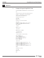
Examples of Programs (Quick Basic by Microsoft) ............................57
Example with RS-232-C Interface ...........................................................57
Example with IEEE-488 Interface ...........................................................58
11.0 —
Maintenance .............................................................................59
11.1 Optical Head.............................................................................................59
11.2 Maintenance of the LDS1000 Electronic Controller ............................59
11.3 Cables........................................................................................................60
RS-232-C Cables........................................................................................60
IEEE-488 Cable..........................................................................................60
Sensor Interface Cable ............................................................................61
Analog Output Cables .............................................................................61
Measurement Synchronization Input Cable.........................................61
Beam Signal Output Cable......................................................................61
v
EDH0170En1020 — 07/11
LDS1000
Controller for Laser Diode Sensors
12
A
B
—
Appendices ...............................................................................62
Example of Program Using RS-232-C Link.............................................62
IEEE-488 Link Characteristics ................................................................63
IEEE-488 Functions Supported by LDS1000 Controller.......................63
IEEE-488 Function Subsets .....................................................................64
SRQ Using .................................................................................................64
Service form .........................................................................................................67
EDH0170En1020 — 07/11
vi
LDS1000
Controller for Laser Diode Sensors
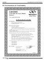
EC Declaration of Conformity
LDS1000
Controller for Laser Diode
Sensors
Year
mark affixed: 2010
EC Declaration of Conformity
The manufacturer:
MICRO-CONTROLE Spectra-Physics,
1 rue Jules Guesde ZI. Bois de l'Epine - BP189
F-91006 Evry FRANCE
Hereby declares that the product:
Description: "LDS1000"
Function: Controller for Laser Diode Sensors
Type of equipment: Electrical equipment for measurement, control and laboratory
use
– complies with all the relevant provisions of the Directive 2004/108/EC relating to electromagnetic compatibility (EMC).
– complies with all the relevant provisions of the Directive 2006/95/EC relating to electrical
equipment designed for use within certain voltage limits (Low Voltage)
– was designed and built in accordance with the following harmonised standards:
NF EN 61326-1:2006 « Electrical equipment for measurement, control and
laboratory use – EMC requirements – Part 1: General requirements »
NF EN 55011:2007 Class A
NF EN 61000-3-2:2006 +A1:2009 + A2:2009 « Electromagnetic compatibility
(EMC) – Part 3-2: Limits - Limits for harmonic current emissions »
NF EN 61010-1:2001 « Safety requirements for electrical equipment for
measurement, control and laboratory use – Part 1: General requirements »
– was designed and built in accordance with the following other standards:
NF EN 61000-4-2
NF EN 61000-4-3
NF EN 61000-4-4
NF EN 61000-4-6
NF EN 61000-4-11
Date : 11/22/2010
Dominique DEVIDAL
Quality Director
MICRO-CONTROLE Spectra-Physics
Zone Industrielle
F-45340 Beaune La Rolande, France
DC2-EN re
rev:A
ev:A
vii
EDH0170En1020 — 07/11
LDS1000
Controller for Laser Diode Sensors
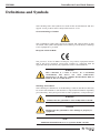
Definitions and Symbols
The following terms and symbols are used in this documentation and also
appear on the product where safety-related issues occur.
General Warning or Caution
The exclamation symbol may appear in warning and caution tables in this
document. This symbol designates an area where personal injury or damage
to the equipment is possible.
European Union CE Mark
The presence of the CE Mark on Newport Corporation equipment means
that it has been designed, tested and certified as complying with all
applicable European Union (CE) regulations and recommendations.
WARNING
This controller is a Class A device. In a residential
environment, this device can cause radioelectric
interferences. In this case, suitable measurements must be
taken by the user of this device.
0.1
Warnings and Cautions
The following are definitions of the Warnings, Cautions and Notes that may
be used in this manual to call attention to important information regarding
personal safety, safety and preservation of the equipment, or important tips.
WARNING
Situation has the potential to cause bodily harm or death.
CAUTION
Situation has the potential to cause damage to property or
equipment.
NOTE
Additional information the user or operator should consider.
EDH0170En1020 — 07/11
viii
LDS1000
Controller for Laser Diode Sensors
Warnings
WARNING
CERTAIN SAFETY PRECAUTIONS MUST BE RESPECTED BEFORE ANY
INTERVENTION ON THE LDS1000 CONTROLLER.
IN ORDER TO COMPLY WITH SAFETY STANDARDS CONCERNING THE
USE OF THIS EQUIPMENT, THE USER MUST TAKE THE FOLLOWING
PRECAUTIONS AND RESPECT THE WARNINGS THAT APPEAR LATER IN
THIS MANUAL.
WARNING: GROUNDING
LDS1000 is a PIECE OF EQUIPMENT DESIGNED TO BE CONNECTED BY A
NON INDUSTRIAL PLUG:
• User safety is ensured by grounding the equipment.
• The user must check the conformity of his electrical installation
• The equipment must be connected to the power supply with a CEE22-type
cable that complies with the EN60950 standard.
Contact your electrician to check the connections of your plugs.
All the sockets that are near your equipment must be equipped with a
ground connection.
Any break in the ground connection can lead to an electric discharge .
WARNING: CONNECTING ADDITIONAL EQUIPMENT
Additional equipment can be connected to the LDS1000 Controller (computer, oscilloscope, etc.).
The connection cables carry VERY LOW VOLTAGE.
The user must make sure that the equipment connected and the cables
used comply with EC standards.
WARNING: LDS SERIES SENSOR
The user must read the warnings in the LDS sensor manual before setting up the equipment.
The sensor must be connected to the LDS1000 Controller using a cable
supplied by us and that has not been modified.
Connection and disconnection must never be carried out to equipment
that is switched on.
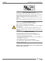
CAUTION: LASER SAFETY
The LDS Series Sensor is a CLASS II LASER INSTRUMENTS according to
the EN-60825-1 standard:
DO NOT STARE INTO BEAM
Max. Power <1 mW @ 670 nm
RAYONNEMENT LASER
NE PAS REGARDER DANS LE FAISCEAU
LASER RADIATION
DO NOT STARE INTO BEAM
APPAREIL A LASER DE CLASSE 2
CLASS II LASER PRODUCT
P <1 mW; λ = 670 nm
IEC60825-1
ix
ATTENTION RAYONNEMENT LASER
EN CAS D'OUVERTURE, EXPOSITION
DANGEREUSE AU FAISCEAU
DANGER. LASER RADIATION
WHEN OPEN, AVOID
DIRECT EXPOSURE TO BEAM
EDH0170En1020 — 07/11
LDS1000
Controller for Laser Diode Sensors
Device
Manufacturer:
LDS1000
1, Rue Jules Guesde, Bât B
ZI. Bois de l’épine
BP189 EVRY 914006 FR
S/N:
Manufactured: 06/2011
Complies with CFR 21 Subchapter J
WARNING: DANGEROUS VOLTAGE
This equipment operates with a supply voltage that can be fatal.
Do not introduce any object into the controller and do not spill any
liquid on the equipment as this could cause a short circuit.
Opening or removing the cover of the equipment exposes you to electric
shocks.
Do not open the equipment. The parts that are inside are of no use to the
user.
CAUTION: SAFETY REGULATIONS
Do not use the instrument in an explosive environment.
Make sure there is no liquid near the instrument.
Make sure that the instrument is not exposed to excessive humidity
(more than 85%).
Do not replace any part and do not modify the equipment in any way
Should the equipment require servicing or repairs send it back to our
head office.
WARNING: UNPLUGGING
Systematically disconnect the plug in all the following cases:
• If the power supply lead or any other cable is damaged or frayed.
• If the mains socket is damaged in any way.
• If the equipment has been exposed to rain, to excessive humidity or if
any liquid has been spilt on it.
• If the equipment has fallen or if the unit is damaged.
• If you think that the equipment requires servicing or repairing.
• When you clean the unit.
NEWPORT SHALL NOT BE HELD LIABLE IF THE ABOVE-MENTIONED
WARNINGS ARE NOT RESPECTED.
EDH0170En1020 — 07/11
x
LDS1000
Controller for Laser Diode Sensors
Controller for Laser Diode Sensors
LDS1000
1.0
Introduction
This manual describes the operations and conditions necessary for the
proper use and working of the NEWPORT LDS1000 Controller.
It also provides the basic maintenance operations that are useful to keep
the instrument in good working order.
IMPORTANT
NEWPORT LDS series sensors are measuring instruments that provides
results of measurements. The calibration certificate drawn up by NEWPORT for each delivery, or when an instrument is newly calibrated must
ALWAYS be supplied with the sensor. It provides the values of the parameters that must be stored in the memory of the LDS1000 electronic controller so that the instrument gives accurate measurements. BEFORE any
measuring operation, the operator must make sure that the parameters
that are used by the electronic controller are the ones that the instrument is designed to use. Refer to the corresponding chapter to check and
modify the sensor parameters.
RECOMMANDATIONS
You are strongly advised to read the chapter entitled “First use” carefully before connecting your autocollimator.
2.0
Description
The LDS1000 Controller is designed to drive sensors of the NEWPORT LDS
series (for example, LDS-Vector autocollimator or STR500-H rectitude sensor). The latter are compact and self-contained measuring instruments.
The LDS1000 electronic controller provides the means of displaying angular variations by measuring the movement of a spot of light on a position
sensing device. It has the capacity, off-line, to store up to 2048 measurements (14336 measurements with the extended memory option) and to calculate the averages of these measurements.
When linked to a personal computer it provides the possibility of processing and recording the measurements.
This manual is designed to facilitate the use of the LDS1000 Controller for
all its modes of operation.
A dedicated user’s manual exists which describes and facilitates the use of
the LDS-Vector sensor.
1
EDH0170En1020 — 07/11
LDS1000
Controller for Laser Diode Sensors
2.1
Equipment
The LDS1000 electronic controller is delivered with:
• A RS-232-C lead.
• The present user’s manual.
• The LDS-TOOLS Software.
• A connection cable (5 or 10 meters, depending on the order).
• As well as the extra accessories and options that may be ordered.
The sensor is delivered in a protection case which contains:
• The optical head.
• The control certificate.
• It's own user’s manual.
ATT
EN
CA ENTION
DA S D'O
RAYO
DANGNGEREUVERTU
NNEM
USE
ENT
WH ER. LAS
AU RE, EXP
LAS
ECT
EN
FAI
ER
OSITIO
ER
EXP OPEN,
RADIA SCEAU
OSUR AVO
N
E TO ID TION
BEA
M
DIR
NE PAS RAYONN
REGARD EMENT
ER DAN LASER
S LE
LAS
DO NOT ER RAD
FAISCEA
U
APPARE STARE IATION
IL A LAS INTO BEA
CLASS
M
II LAS ER DE CLA
ER PRO SSE
P <1
DUCT 2
mW;
λ = 670
IEC608
25-1 nm
2.2
Modes of Operation
2.2.1
Manual Mode
The LDS1000 Controller displays angular rotation values of the mirror on a
frontal display screen. The operator uses the display and the active buttons on the front panel to:
• Read the measurements.
• Modify the integration constant.
• Define the zero point.
• Program the parameters of the connected sensor.
• Modify the communication parameters (RS-232-C or IEEE-488).
• Activate the analog outputs where available.
Refer to the chapter entitled: “Off-line use”.
EDH0170En1020 — 07/11
2
LDS1000
Controller for Laser Diode Sensors
2.2.2
Remote Mode
When linked to a computer by RS-232-C or IEEE-488 connection, the
LDS1000 Controller communicates by ASCII messages. The buttons on the
front panel of the controller are no longer valid.
The following functions are possible:
• Reading the controller’s programmed parameters.
• Modification of the integration constant.
• Transmission of instantaneous values measured.
• Acquisition in the controller’s internal memory, of a number N of points,
at the frequency F.
• Acquisition in the controller’s internal memory, of a number N of points,
at the frequency F, the beginning of the acquisition is started by an
external signal (Trigger).
• Acquisition in the controller’s internal memory of a number N of points,
each acquisition being started by an external signal (Trigger).
Refer to the chapter entitled: “Use with a computer interface”.
2.2.3
Analog Mode
Analog outputs are only available on models that are equipped with this
option. This must be specified at the time of ordering.
There are two voltages at the analog outputs that are respectively proportional to the angular measurements Y and Z of the equipment.
This enables:
• Connection to an analog acquisition chain.
• Visualization of positions on an oscilloscope.
• Use of the LDS-Vector autocollimator for analog controls.
These outputs are obtained by a digital/analog conversion of the values calculated by the controller.
This conversion is carried out in real time at a frequency of 2000 Hz.
Refer to the chapter entitled: “Off-line use”.
2.3
Available Versions
2.3.1
Controller
The electronic controller is available in eight versions that offer different
measuring possibilities. The references are as follows:
LDS1000 Controller
with:
BB
CC
LDS1000-OPT BB CC
NN
No cable.
01
Cable length 5 meters.
02
Cable length 10 meters.
NN
No controller.
02
Standard controller European standard (220V,
2 manuals and EU cable).
12
Analog option controller, EU standard.
22
14K memory option controller, EU standard.
32
2-option controller, EU standard.
3
EDH0170En1020 — 07/11
LDS1000
Controller for Laser Diode Sensors
2.3.2
Sensor
Autocollimator, bilingual user’s manual
2.3.3
LDS-Vector
Accessories and Additional Equipment Kits
Calibration blade kit, with certificate
LDS-CAL01
2-theta adjustable mount
LDS-SL
2-theta + XY adjustable mount
LDS-SLXY
4 movement adjustable mount on X26 (complete, for LDS-Vector)
LDS-X26-V
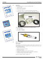
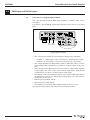
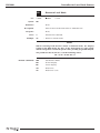
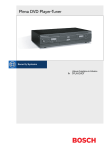
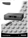
2.4
Dimensions
– FRONT VIEW –
3.29
(83.5)
.83 (21)
13.0 (329.5)
Depth 13.9 (352)
SENSOR
CONNECTOR
Y&Z
OUTPUTS
– REAR VIEW –
IEEE-488
I
O
!
TRIG PWOK
INPUT INPUT
EDH0170En1020 — 07/11
4
RS-232-C
LDS1000
3.0
Controller for Laser Diode Sensors
Principle of Operation
3.1
Laser Diode Sensors
The emission is performed by a Laser diode controlled and modulated at
10 kHz.
The reception is performed by a position sensing device that provides analog voltages.
From the electronic controller’s point of view, that becomes:
• Supply the necessary power to the laser diode and to the pre-amplifying
electronic controller.
• Monitor break down and defects.
• Collect the return signals from the analog sensor.
This data is processed by the controller, corrected according to the parameters provided by calibration and usable depending on the different
modes (display, memorization, transmission to the computer interface,
analog output [available as an option]).
3.2
Electronic Controller
The LDS1000 Controller performs:
• Fast acquisition at a set frequency of 2 kHz.
• Analog to digital conversion.
• Correction and integration calculation.
• Memory and display management.
Its technology is based on a 68000, 16 MHz microprocessor.
This controller offers a clear display of the values measured on a luminous
screen and communication via RS-232-C and IEEE-488 interfaces.
One particular model is available with calibrated analog outputs, that are
proportional to the values measured.
5
EDH0170En1020 — 07/11
LDS1000
4.0
Controller for Laser Diode Sensors
Specification
The LDS1000 electronic controller works with the LDS-Vector electronic
autocollimator. Characteristics of the optical head are given in the individual manuals.
The measurement results can only take on their full meaning in relation to
a unit that represents the value to be measured (distance, angle…). The
controller enables the result to be displayed on the unit that corresponds
to the sensor used.
4.1
General Characteristics
4.1.1
LDS-Vector Optical Head
• Wavelength
• Peak power
• Modulation
• Beam diameter
• Beam direction
• Equivalent focal length
• Beam divergence
• Ocular field
• Measurement range
• Weight
4.1.2
LDS1000 Controller
• Microprocessor
• Display
• Interfaces
• Measurement memory
•
•
•
•
•
4.1.3
EDH0170En1020 — 07/11
Analog output
TTL TRIGG input
TTL PWOK output
Power supply
Consumption
Measurements
• Digital resolution
• Measurement range
• Measurement error
• Max. measuring noise
• Sampling frequency
• Digital integration
6
670 nm
<1 mW
10 kHz
31 mm
<0.5 mrad in relation with autocollimator body
280 mm
0.1 mrad
±15 mrad
±2000 µrad
1.065 kg
68000 (32 bits - 16 MHz)
2 x 20 characters, adjustable brightness
RS-232-C and IEEE-488
2048 spots or
14336 spots depending on the option
Available as an option
Measurement synchronization
Beam signal
90/264 VAC, 50/60 Hz
30 VA
0.1 µrad
±2000 µrad
± (1 ±0.02 x measurement.) µrad (i.e. ±2%)
0.02 µrad/√Hz
2000 Hz
from 0.5 msec to 1 sec
LDS1000
Controller for Laser Diode Sensors
4.1.4
Environment
The performances of an optical sensor greatly depend on the conditions in
which it is used.
The contractual characteristics are specified in the manual that goes with
each sensor of the LDS series.
The operating limits of the LDS1000 Controller are the following:
• Operating temperature
+15 °C to +25 °C
• Humidity
10% to 80%
• Storage temperature
-10 °C to +50 °C
Refer to the paragraph entitled “Specification Validity” in each user’s manual for the performances of the sensors according to the conditions of use.
4.1.5
4.1.6
RS-232-C and IEEE-488 Interfaces
RS-232-C interface
Baud rate
300 to 19200
IEEE-488 interface
Mode
SRQ management
Analog Outputs
Analog outputs are only available if the option has been chosen.
• Refresh frequency
2000 Hz
• Digital low-pass filter
1 to 2000 Hz
• Output range
±10 V
• Scale factor
5 mV/incr to 1000 mV/incr
• Resolution
0.5 increment
• Electronic noise
1 mV rms
• Distortion
0.5% (electronic)
• Maximum Offset
50 mV typical
• Output impedance
10 Ω
• Discrepancy equivalent to a pure delay of 1.1 msec (without integration).
• Attenuation equivalent to the one of an order 1 low-pass filter with
600 Hz cutoff frequency.
WARNING: SPECTRAL WITHDRAWAL
The analog outputs use an intermediary calculation stage that is based
on a sample at 2000 Hz. This will limit the use of the LDS sensor for
studying signals that do not have a significant spectral component over
1000 Hz (this sort of component would find themselves “withdrawn” and
would appear for lower frequencies).
4.2
Validity of Specifications
Refer also to the paragraph entitled “Specification Validity” in each user’s
manual for the performances of the sensors according to the conditions of
use.
7
EDH0170En1020 — 07/11
LDS1000
Controller for Laser Diode Sensors
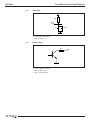
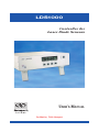
4.2.1
Calibration
A reading of the linear errors according to the angle measured is provided
with each sensor. This calibration certificate gives, in particular, the value
of the principal parameters to be used to configure the LDS1000 electronic
controller:
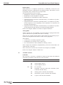
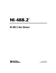
• S/N: Series number of the optical head.
• Type: RT (Rotation) for LDS-Vector.
+Z
ATT
EN
ENT
CAS
ION
DAN D'OU RAY
DAN GER VER ONN
GER EUS TUR EME
DIRE WHE . LAS E AU E, EXPNT
LAS
CT EXPN OPE ER
FAIS
OSIT
ER
RAD
CEA
OSU N, AVO
IATIO U ION
RE
N
TO ID
BEA
M
NE PAS RAYO
REGA NNEM
RDER
ENT LASE
DANS
R
LASE
DO NOT R RADI LE FAISCEAU
STAR ATION
APPA
E INTO
REIL
BEAM
CLAS A LASE
S II LASE R DE
CLAS
R PROD
SE 2
P <1
mW;
λ = 670 UCT
IEC60825
nm
-1
+Y
+X
+Y
+Z
•
•
•
•
•
•
•
•
X: Beam Axis; Y: Horizontal Axis; Z: Vertical Axis.
– Type RT (Rotation):
Y: Rotation around Y axis.
Z: Rotation around Z axis.
– Type TR (Translation):
Y: Parallel translation with Y axis.
Z: Parallel translation with Z axis.
Ycoef: Linear correction factor for axis Y.
Yincr: Count increments for axis Y.
Yunit: Unit displayed for axis Y.
Yofs1, Yofs2: Channel Y electronic offsets.
Zcoef: Linear correction factor for axis Z.
Zincr: Count increments for axis Z.
Zunit: Unit displayed for axis Z.
Zofs1, Zofs2: Channel Z electronic offsets.
These parameters were optimized when the instrument was calibrated in
order to obtain the best results. You are advised not to modify them without reason.
These parameters have been defined for the following conditions of use:
• Temperature
22 °C ±2 °C
• Mirror diameter
>31 mm
• Reflectivity
80% at 670 nm
• Working distance
0.1 m
4.3
Noise Reduction
The LDS1000 Controller constantly carries out acquisitions at a rate of 2000
values per second.
These acquisitions are dealt with on request (transformation of electric signals into metrological values) for display or emission on a connection.
Depending on the programming of the electronic controller, the returned
value corresponds either to the last acquisition carried out (no average) or
to the average of the last N acquisitions.
EDH0170En1020 — 07/11
8
LDS1000
Controller for Laser Diode Sensors
In the second case, a low-pass digital selection is carried out which reduces
the noise.
The noise reduction evolves like the square root of the number N of averaged samples, which is itself equal to the averaging time to acquisition period ratio.
The acquisition period is always equal to 0.5 msec (2 kHz).
The duration of the averaging is fixed by the integration constant that can
be parametered INTG.
Refer to the user’s manual of the LDS sensor concerned.
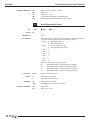
4.4
Offset Coefficient Adjustment
The Yofs1, Yofs2, Zofs1 and Zofs2 coefficients are normaly set to zero
value.
When the reflected light is becoming low, because of poor reflectivity or
small mirror aperture, it is necessary to take into account the value of the
electronic offsets of the detector.
The LDS1000 Controller is designed to make this correction very easily, by
introducing offset coefficients into its memory.
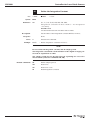
The following procedure must be accomplished:
❶ The values of offsets are reached when the instrument does not receive
any light.
In order to get these values, place a black screen in front of the exit
pupil of the instrument.
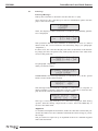
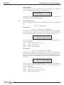
The requested values are then dispayed by the LDS1000 in the specific
test mode, described in chapter 7.3.
MAIN => MENU (F5) => NEXT (F4) => TEST (F2)
SY 00015 00027 MAIN
SZ 00012 00019
The first line gives Yofs1 and Yofs2.
The second line gives Zofs1 and Zofs2.
❷ Take notes of these values and go to LDS1000 parameter setting, as
explained in chapter 7.4.
9
EDH0170En1020 — 07/11
LDS1000
5.0
Controller for Laser Diode Sensors
Starting the Equipment
5.1
Setting Up
The setting up of the sensor is explained in each user’s manual of the LDS
instruments.
RECOMMANDATION
You are advised to read the user’s manuals corresponding to each sensor
delivered. They contain important information for optimal use of the
instruments. These instructions can vary from one sensor to another.
5.1.1
Mounting
Small movement measurements require specific precautions as far as the
quality of the mounting of the equipment is concerned. It is particularly
important to make sure that the sensor, the reflector and their corresponding supports are solid
5.2
Electric Connections
CAUTION
Before connecting check that all equipment is switched off.
CAUTION
Do not use any cable other than the one supplied by NEWPORT.
The cable provided connects the sensor to the electronic controller. The
male part should be connected to the optical head, the female part to the
controller. Please ensure that all connections are correctly screwed in.
The cable is available in two standard lengths:
Cable for LDS1000, length 5 meters
Cable for LDS1000, length 10 meters
LDS1000-OPT01NN
LDS1000-OPT02NN
For longer lengths, please consult us.
A lead ensures the connection to the mains supply on a switch and fuse
base.
The controller is equipped with a self-selecting input voltage power supply
(from 90 V to 250 V).
Set the switch to "0" (OFF) position.
EDH0170En1020 — 07/11
10
LDS1000
Controller for Laser Diode Sensors
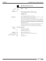
5.3
Power Up
5.3.1
Power Up Messages
Link up the controller to the mains. Set the switch to “I” (IN).
Once turned on, the controller goes into its initialization phase and displays a welcome message.
LDS1000
NEWPORT
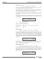
Then, the display of values measured according to programming parameters is displayed:
Y=Z=+
2.6 krad MENU
8.5 krad CONF
This presumes that the autocollimator is stationary in front of a mirror
which sends the correct beam into the measuring range (see paragraph:
“Alignment”).
In other cases, the controller displays the value of the limits of the measuring range (the most frequent being -2000 µrad) instead of the value measured on the given axis:
Y=-2000.0 krad MENU
Z=+2000.0 krad CONF
See paragraph: “Alignment”.
Other possible messages:
INTERNAL ERROR $103
LASER ERROR
LASER ERROR: This message indicates a connection error in the optical
head or a laser diode emission fault.
LDS1000 CONTROLLER
REMOTE
MODE
This message indicates that the controller is connected to a computer on
which software is running, which has sent the command to freeze the display. Reset the software parameters to regain control.
ANALOG OUTPUT
100 ms
Gx1
MAIN
CONF
This type of message indicates, for controllers equipped with analog
options, that the analog output mode is active. Press the MAIN key to
return to the main menu.
5.3.2
Alignment
To visualize an angular measurement, make sure that the return beam penetrates the LDS-Vector autocollimator and that the return energy is powerful enough.
The procedure for rapid set up is explained in the user’s manual supplied
with each instrument.
11
EDH0170En1020 — 07/11
LDS1000
6.0
Controller for Laser Diode Sensors
Configuring the Equipment
The controller is configured in manual mode, using the buttons and the display available on the front panel of the LDS1000 Controller. This must be
done before the instruments can be used.
6.1
Sensor Configuration
The LDS1000 electronic controller works with an LDS-Vector electronic
autocollimator.
To simplify programming and to minimize the risk of errors, the LDS1000
electronic controller has a memory that can store all the parameters of 10
different sensors. Only Manual mode makes it possible to modify the number of the sensor being used, as this modification requires manual adjustment on the controller (physically connecting the sensor required).
To configure the sensor you will need to consult the control statement
delivered with each piece of equipment. Should you lose it, a duplicate of
this document which is of great importance is kept by our metrology
department. Just note the number that is marked on the sensor and we will
be able to send you a copy of the document.
The configuration of the sensor is carried out in manual mode and enables:
• The active sensor to be selected.
• The parameters of the active sensor to be visualized.
• The parameters of the active sensor to be modified.
See the chapter entitled: “Off-line use”.
6.2
Interface Configuration
Manual mode enables the parameters and the communication mode of the
controller to be chosen. It is useful to check these values before proceeding with a connection to a computer. This must be done before using the
instrument in Interface Mode.
The LDS1000 Controller communicates with a computer via two standard
protocols available:
• RS-232-C.
• IEEE-488.
6.2.1
RS-232-C Interface
The RS-232-C protocol is available on most commercial computers on ports
COM1 or COM2. The LDS1000 Controller is delivered with a RS-232-C lead
comprising a classical Sub-D9 connector, as well as a Sub-D9/Sub-D25 adapter.
Depending on the standard chosen by the computer manufacturer, it is
always possible to carry out the RS-232-C communication with the LDS1000
Controller. A program written on a given computer will be able to use the
RS-232-C outputs available on another computer without any problems (on
the condition that the right number of the port on which the LDS1000
Controller is connected is given).
EDH0170En1020 — 07/11
12
LDS1000
Controller for Laser Diode Sensors
The parameters of the RS-232-C interface are the following:
• BAUD RATE
Interface speed.
• MSG TERM
End of message character.
• WORD LENGTH
Length of the transmitted chain.
• STOP BITS
Number of stop bits.
• PARITY
Parity used by the interface.
6.2.2
IEEE-488 Interface
The IEEE-488 protocol is only possible when the computer is equipped with a
special card that allows IEEE-488 communication. There are several different
models available on the market. Please note that they are not compatible
between themselves. As a result, a software program written for a IEEE-488
card of a model will not work with another IEEE-488 card.
The parameters of the IEEE-488 interface are the following:
• MSG TERM
End of message character.
Instrument’s primary address.
• PRIM ADRESS
• SECOND ADRESS
Instrument’s secondary address.
• TIME OUT
Wait time.
The IEEE-488 interface enables several different instruments to be connected to the same computer input. It is quicker than the RS-232-C interface. For
this connection, the controller operates in SRQ mode.
The parameters of the two communicating instruments must be identical to
obtain the communication (in fact the two instruments must speak the same
language in order to understand each other). The LDS1000 Controller is considered to be a slave in the communication protocol. Its parameters must
therefore be chosen in accordance with those of the master computer.
Cf. Chapter entitled: “Off-line use”.
6.3
Controller Configuration
The LDS1000 Controller has a program and material configuration that
depends on the options chosen at the time of ordering. In particular, the
internal software version, the size of the memory installed and the installation of the analog output option represent information that is accessible in
manual mode.
Moreover, so that you can comfortably use the controller in different
atmospheres, the brightness of the light can be adjusted.
Accessible functions:
• Reading the version.
• Display brightness.
• Memory size.
• Analog output option.
Refer to the chapter: “Off-line use”.
13
EDH0170En1020 — 07/11
LDS1000
Controller for Laser Diode Sensors
6.4
Analog Output Configuration
The analog outputs are only available by manual mode on the models
equipped with this option.
It is possible to modify the following parameters:
Refer to the chapter: “Off-line use”.
NOTE
The analog outputs deliver two voltages that are respectively proportional to the Y and Z measurements of the equipment.
Among other things this enables:
• Connection to an analog acquisition chain.
• Visualization of positions on an oscilloscope.
• Use of the sensor for analog controls.
These outputs are obtained by a digital/analog conversion of the values calculated by the controller.
This conversion is carried out in real time at a frequency of 2000 Hz. It
imposes the following limits:
• Resolution limitation
0.5 increment
• Further measurement distortion
0.5%
• Extra noise
1 mV rms (measured with a
load of 1 MΩ).
• Maximum offset
50 mV typical.
• Discrepancy equivalent to a pure delay of 1.1 msec (without integration).
• Attenuation equivalent to the one of an order 1 low-pass filter with
600 Hz cutoff frequency.
The output voltages take into account the averaging defined by INTG. The
full scale voltage variation (±10 V) matches the full scale measurement variation, i.e. a scale factor of 5 mV/increment.
A multiplying factor defined by GAIN (1 to 200) makes it possible to change
this scale factor from 5 to 1000 mV/increment. The gain comes with a limitation of the angular range that can be visualized (outputs limited at ±10 V).
The impedance of the outputs if equal to 10 Ω and the maximum current
they can deliver is 4 mA.
EDH0170En1020 — 07/11
14
LDS1000
7.0
Controller for Laser Diode Sensors
Off-Line Use (Manual Mode)
The LDS1000 Controller has two modes of operation.
Manual mode which enables:
• The configuration of the controller in accordance with the parameters
of the sensor used.
• To carry out measurements on values displayed.
• To modify the integration time, and the display mode.
• To parameter the communication interface.
• To select the analog outputs (if option available).
Interface mode which enables:
• Flying spot reading of values measured,
• Execution of acquisition sequences that are synchronized or not.
• Reading the sensor status.
Manual mode is valid when the autocollimator is in off-line use, to perform
measurements from the controller display. It is also used to parameter the
computer interface or to access the analog outputs option (if it exists).
7.1
Access to Manual Mode
Manual mode is directly accessible on the controller at the time of Power
up, except in the following cases:
• Sensor non connected or damaged (Laser error).
• Analog output mode valid (Refer to the corresponding chapter).
• Communication in progress via RS-232-C or IEEE-488 (Refer to the
Interface Mode chapter).
The starting point is the main Menu which is the controller’s usual mode of
operation.
Y=Z=+
2.6 krad MENU
8.5 krad CONF
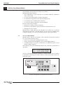
Access to the different Menus, parameter scrolling and the choice of values
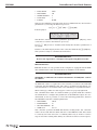
is obtained by pressing one of the 5 buttons on the front panel of the controller (F1 to F5).
LDS1000
F5
F1
F2
F3
F4
F5
F1
F2
F3
F4
Position of the buttons on the LDS1000 Controller.
15
EDH0170En1020 — 07/11
LDS1000
Controller for Laser Diode Sensors
The mnemonics corresponding to the function of each button are indicated
by the display shown by the button.
For example, in the main menu MAIN, the F5 key enables the function
MENU to be selected, and the F4 key selects the function CONF. The
other keys F1, F2 and F3 have no effect.
WARNING
As a result the keys do not always correspond to the same functions.
7.2
Manual Mode Functions
The main menu gives access to two sub-menus:
• MAIN => MENU (F5 key)
Ce Mode permet l’accès aux fonctions suivantes:
MEMO
Display freeze.
ZERO
Display relative to a current position.
GRAP
Graphic display.
INTG
Modification of the integration constant.
ILLU
Display the light received.
TEST
Test Mode (maintenance).
• MAIN => CONF (F4 key)
This Mode gives access to the following functions:
HEAD
Reading/Modification of current sensor parameters.
Memorization / Selection of 10 different sensor configurations.
COMM
Choice of communication parameters(RS-232-C, IEEE-488).
RACK
Information on the software version, the available memory and
the display brightness.
ANLG
Commutation to analog outputs (only if the option exists).
The rolling menus use the following symbols and mnemonics:
EDIT
Modification of current parameters.
VISU
Visualization of current parameters.
NEXT
Information on the software version, the available memory and
the display brightness.
STD
Reset with default values.
SET
Save modifications (after EDIT).
YES
Message confirmation.
NO
Abandon.
>>>
Scrolling of modifiable parameters (or cursor movement).
+++
Next highest value (+1 for digital values).
---
Lower value (-1 for digital values).
MAIN
Return directly to main Menu.
After any modification, the configuration will be saved when the equipment
is switched off.
EDH0170En1020 — 07/11
16
LDS1000
Controller for Laser Diode Sensors
MASTER RESET
On switching on, if you press the F5 key for a few seconds, the controller
suggests changing all the parameters to default values.
LDS1000
??
NO
MASTER RESET
?? YES
Selecting YES (F4 key) will destroy all the data fed into the controller and
will replace all values with default values.
7.3
Measuring Functions
Access to measuring functions, from the main menu, is done with the F5
key:
MAIN => MENU (F5) => …
7.3.1
Display Freeze
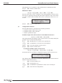
MAIN => MENU (F5) => MEMO (F1)
The display freeze is useful when carrying out measurements of a vibrating
or moving system spread out over time. The display is frozen and the two
values that correspond to the same instant are available on the screen.
Y=- 362.9 µrad MAIN
Z=
403.8 µrad
RUN
It is therefore possible to read them without haste (this is a flying spot picture of a position).
7.3.2
MAIN
(F5) Return to main menu.
RUN
(F4) Normal display.
MEMO
(F4) Freeze the display.
Offset Origin
MAIN => MENU (F5) => ZERO (F2)
This mode, also called relative display, makes it possible to set the current
point as the origin. The values displayed are therefore given in relation to
this point. This mode is practical to find out the angular distance between
two given positions, without having to adjust the zero point to the center of
the sensor.
Y=
125.3 µrad MAIN
Z=83.9 µrad MEMO
However, it is necessary to make sure that you do not go beyond the min.
and max. limits on the cell. You are advised to set the first point near the
center of the sensor.
MAIN
(F5) Return to main menu.
MEMO
(F4) Freeze the relative display.
RUN
(F4) Relative display.
17
EDH0170En1020 — 07/11
LDS1000
Controller for Laser Diode Sensors
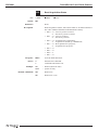
7.3.3
Integration Constant
MAIN => MENU (F5) => INTG (F3)
The accuracy that can be obtained on a measurement depends on the number of readings carried out for that measurement.
In manual mode, the LDS1000 electronic controller carries out measurements at a frequency of 2 kHz. Its own resolution at this frequency is
0.8 µrad when using a standard LDS-Vector autocollimator.
By calculating the average of a large number of measurements, it is possible to obtain a much higher resolution, to the detriment of the system’s
pass band.
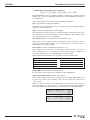
The LDS1000 Controller carries out a sliding average of N successive values, in relation to the INTG parameter that can be selected with this menu
(N = 2 x INTG).
INTG =
100 ms
--+++
7.3.4
---
(F2) Lowest INTG value.
+++
(F3) Highest INTG value.
MAIN
(F5) Return to main menu.
SET
Possible values:
INTG = 0,5; 1; 2; 5; 10; 20; 50; 100; 200; 500; 1000
Default value:
INTG = 100
Unit:
msec
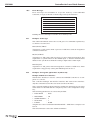
Graphic Display
MAIN => MENU (F5) => NEXT (F4) => GRAP (F3)
In order to facilitate alignments, a display in the form of a Bar-Graph is recommended. For each axis, the number 8 digit is considered as the optical
center of the autocollimator. The angles measured successively light up the
adjacent digits (7 on each side), logarithmically for accurate alignment
mode. Positive space values light up the digits to the right. The alignment
around the center of the sensor is achieved by switching off as many digits
as possible.
======
=====
MAIN
ZERO
In alignment mode, a ZERO function (F4) enables measurements to be performed in relation to the current position which becomes a reference point.
MAIN
7.3.5
(F5) Return to main menu.
Display Light Received
MAIN => MENU (F5) => NEXT (F4) => ILLU (F1)
To check if the instrument is working properly, make sure that the rate of
light returned to the sensor is sufficient. This mode is especially useful for
setting up the instrument in complex assemblies, in order to avoid substantial vignetting. The best results are obtained when a maximum amount of
light is received.
LIGHT LEVEL
100 %
EDH0170En1020 — 07/11
18
MAIN
LDS1000
Controller for Laser Diode Sensors
The display is in % in relation to the nominal value established at 100%.
MAIN
7.3.6
(F5) Return to main menu.
Maintenance Mode
MAIN => MENU (F5) => NEXT (F4) => TEST (F2)
Here the brut value of the 4 channels of the analog/digital converter from
the sensor is displayed. Interpreting the values depends on the sensor that
is in place. Their read-out enables the sensor’s electronic offset to be corrected.
SY 06352 21857
SZ 32165 00849
MAIN
7.4
MAIN
(F5) Return to main menu.
Configuration Functions
Here we find the way to parameter the following elements:
• Parameter input of the sensor used.
• Parameter input of the controller.
• Interface parameter input.
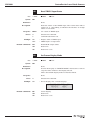
7.4.1
Parameter Input of the Current Sensor or the Memorized Sensors
MAIN => CONF (F4) => HEAD (F1)
This mode displays the number of the current sensor (currently valid) and
provides access to the following menus:
7.4.1.1
EDIT
(F1) Modification of current sensor parameters.
VISU
(F2) Visualization of current sensor parameters.
CHGE
(F3) Choosing another current sensor.
MAIN
(F5) Return to main menu.
Selecting the Number of the Current Sensor
MAIN => CONF (F4) => HEAD (F1) => CHGE (F3)
From this menu, it is possible to modify the number of the current sensor.
HEAD NUMBER : 0 SET
--+++
VISU
The display then takes into account the parameters associated with the
number of the current sensor.
---
(F2) Previous number (-1).
+++
(F3) Next number (+1).
VISU
(F4) Visualization of parameters of the sensor envisaged.
SET
(F5) Save the new configuration.
19
EDH0170En1020 — 07/11
LDS1000
Controller for Laser Diode Sensors
7.4.1.2
Modification of Current Sensor Parameters
MAIN => CONF (F4) => HEAD (F1) => EDIT (F1)
Each NEWPORT sensor is delivered with a calibration certificate which
enables the correct programming parameters for the LDS1000 Controller to
be established.
This certificate gives the values of the following parameters:
S/N: Series number of the optical head.
A number is allocated to each sensor. It means it can be identified and its
progress can be monitored.
Type: Y axis horizontal (TR) or vertical (RT).
This indication specifies the type of measurements carried out by the sensor. Thus RT, for rotation designates an autocollimator. This value is used
by some programs for a correct display.
Ycoef, Zcoef: Linear correction factor for the axis Y or Z.
The sensor can be calibrated on a measuring bench. The given value of
Ycoef or Zcoef minimizes linear errors in the direction concerned. It is a
multiplying factor of the display.
Yincr, Zincr: Counter increment for the axis Y or Z.
The resolution of each sensor is limited by physical factors (electronic
noise, enlargement, etc.). The value of Yincr or Zincr given is adapted to
the sensor delivered. It is a multiplying factor of the display.
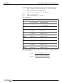
Different measurement limits correspond to each increment value:
0.1
0.2
0.5
1
2
-199.99
-399.98
-999.95
-1999.9
-3999.8
…
…
…
…
…
+199.99
+399.98
+999.95
+1999.9
+3999.8
5
10
20
50
-9999.5
-19999
-39998
-99995
… +9999.5
… +19999
… +39998
… +99995
Yunit, Zunit: Unit displayed for the axis Y or Z.
It is the unit for which the sensor parameters are established.
Yofs1, Yofs2, Zofs1, Zofs2: Electric offset values.
These values enable the sensor resolution to be refined while taking into
account a possible offset reading. The correct values are achieved in
TEST mode.
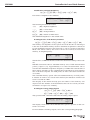
In EDIT mode the values of the parameters stored for the current sensor
can be modified. As a precaution, a confirmation message asks whether
you really want to modify the current sensor (and specifies the number):
EDH0170En1020 — 07/11
20
MODIFY HEAD 0
NO
YES
S/N = 000000
>>>
--+++
SET
NEXT
LDS1000
Controller for Laser Diode Sensors
For all the parameters, a modification menu uses the following functions:
>>>
(F1) Scrolling of possible parameters (or cursor movement).
---
(F2) Lower value (-1 for digital values).
+++
(F3) Next highest value (+1 for digital values).
NEXT
(F4) Next parameter.
SET
(F5) Save and exit EDIT mode.
List of parameters:
S/N
Type
Ycoef
Yincr
Yunit
Yofs1
Yofs2
Zcoef
Zincr
Zunit
Zofs1
Zofs2
Designation
Series number of
the optical head
Sensor type
Linear correction
factor for Y axis
Counter increment
for Y axis
Unit displayed
for Y axis
Electric offset
values for Y
Linear correction
factor for Z axis
Counter increment
for Z axis
Unit displayed
for Z axis
Electric offset
values for Z
Available Values
Default Value
6 digits:
000000
000000 à 999999
Y axis horizontal (TR)
RT
or vertical (RT)
5 digits:
04000
00100 to 29999
0.1; 0.2; 0.5; 1; 2; 5;
1
10; 20; 50
µrad; sec; mrad; nm;
unit
µm; mm; unit
5 digits:
00000
00000 to 32767
5 digits:
04000
00100 à 29999
0.1; 0.2; 0.5; 1; 2; 5;
1
10; 20; 50
µrad; sec; mrad; nm;
unit
µm; mm; unit
5 digits:
00000
00000 to 32767
The values displayed on the screen of the controller are obtained by the
following calculation:
YDisplayed =
YCalculated x (Ycoef x 10 x Yincr)
10
ZDisplayed =
ZCalculated x (Zcoef x 10 x Zincr)
10
21
EDH0170En1020 — 07/11
LDS1000
Controller for Laser Diode Sensors
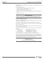
7.4.1.3
Display of Result in Arc-Seconds (LDS-Vector)
MAIN => CONF (F4) => HEAD (F1) => EDIT (F1)
The calibration certificate gives the values Ycoef, Zcoef, Yincr and Zincr for
result display in µrad. In general, Yincr and Zincr are equal to 1. The resolution of the display is then 0.1 µrad.
To display the result in arc-sec:
1 arc-sec = 4.85 µrad
1 µrad = 0.2062 arc-sec
Thus: Y µrad = (0.20 x 1.0309 x Y) arc-sec
Thus we will use the increments Yincr = 0.2 and Zincr = 0.2. That gives display limits of -400 to + 400.
The values Ycoef and Zcoef are corrected by 1.0309:
Ycoef1 = Ycoef x 1.0309 (rounded to the nearest unit).
Zcoef1 = Zcoef x 1.0309 (rounded to the nearest unit).
The unit sec will be chosen.
You are advised not to delete the initial parameters, in µrad. You only need
to program a new sensor number.
7.4.1.4
Programming a New Sensor
When an LDS-Vector autocollimator is delivered with its electronic controller, the sensor parameters are fed into the memory of the controller.
The number 0 is used for the current sensor.
The other memories are normally empty, and the values of the parameters
are therefore equal to the default values.
To program a new sensor, a spare place must be found, generally recognizable when S/N = 000000. You can choose to delete an existing sensor.
Access to the mode that enables rapid visualization of the various heads is
obtained by the sequence:
MAIN => CONF (F4) => HEAD (F1) => CHGE (F3)
HEAD NUMBER : 0 SET
--+++
VISU
It is then possible to modify the number of the current sensor:
---
(F2) Previous number (-1).
+++
(F3) Next number (+1).
VISU
(F4) Visualization of parameters of the sensor envisaged.
SET
(F5) Save the new configuration.
Programming the new sensor is done by the EDIT menu (see modification of sensor parameters).
EDH0170En1020 — 07/11
22
LDS1000
Controller for Laser Diode Sensors
7.4.1.5
Visualization of Current Sensor Parameters
MAIN => CONF (F4) => HEAD (F1) => VISU (F2)
You are advised to check that the current sensor really matches the sensor
that is currently connected to the controller. This Visualization mode is
easily accessible and provides the explicit values of the current sensor
parameters.
S/N = 000000
END
NEXT
Check that the series number really matches that of the connected sensor.
For more certainty, compare the values of the parameters to those given in
the calibration certificate supplied with the sensor.
In case of nonconformity, it is necessary to:
• Either find another number of the current sensor (especially if the series
number does not match): CHGE Menu.
• Or modify the current sensor parameters: EDIT Menu.
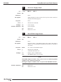
7.4.2
Communication Parameter Input
MAIN => CONF (F4) => COMM (F2)
Access to this menu enables the parameters and the choice of communication mode of the controller to be modified. It is useful to check these values
before connecting to a computer. This must be done before using the
instrument in Interface Mode.
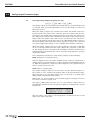
The COMM menu makes this selection possible in manual mode
REMOTE RS 232c MAIN
>>>
EDIT
STD
This message indicates that the communication is programmed in RS-232-C.
Access to the following functions is then possible:
>>>
(F1) Changing RS-232-C <=> IEEE-488.
EDIT
(F2) Modification of the parameters of the selected interface.
STD
(F3) Change to default values of the selected interface.
MAIN
(F5) Return to main menu.
The communication mode can be modified from this menu using the >>>
(F1) key.
23
EDH0170En1020 — 07/11
LDS1000
Controller for Laser Diode Sensors
7.4.2.1
Modification of RS-232-C Parameters
MAIN => CONF (F4) => COMM (F2)
The RS-232-C interface is active if the display is as follows:
REMOTE RS 232c MAIN
>>>
EDIT
STD
Otherwise, the >>> (F1) key provides access to this menu.
In EDIT mode the values of the parameters stored for the RS-232-C interface can be modified.
For all the parameters, a modification menu uses the following functions:
>>>
(F1) Scrolling of possible parameters (and their status).
NEXT
(F4) Next parameter.
SET
(F5) Save and exit EDIT mode.
MAIN
(F5) Return to main menu.
List of parameters:
Designation
MSG TERM End of sequence
terminator
BAUD RATE Transmission
Speed
WORD LENGTH
Length of
the string sended
STOP BITS Stop bit
number
PARITY
Parity
7.4.2.2
Available Values
CR; LF; CR LF; LF CR
Default Value
CR
300; 600; 1200; 2400;
4800; 9600; 19200
7; 8
9600
1; 2
NONE; ODD; EVEN
8
1
NONE
Modification of IEEE-488 Parameters
MAIN => CONF (F4) => COMM (F2)
The IEEE-488 interface is active if the display is as follows:
REMOTE IEEE488 MAIN
>>>
EDIT
STD
Otherwise, the >>> (F1) key provides access to this menu.
In EDIT mode the values of the parameters stored for the IEEE-488 interface can be modified.
For all the parameters, a modification menu uses the following functions:
EDH0170En1020 — 07/11
>>>
(F1) Scrolling of possible parameters (or cursor movement).
---
(F2) Lower value (-1 for digital values).
+++
(F3) Next highest value (+1 for digital values).
NEXT
(F4) Next parameter.
SET
(F5) Save and exit EDIT mode.
MAIN
(F5) Return to main menu.
24
LDS1000
Controller for Laser Diode Sensors
List of parameters:
Designation
MSG TERM End of sequence
terminator
PRIM ADRESS
IEEE-488
primary adress
SECOND ADRESS IEEE-488
secondary adress
TIME OUT
Communication
time-out
7.4.2.3
Available Values
CR; LF; CR LF; LF CR
2 digits:
00 to 30
2 digits:
00 to 30
0.01 to 10 sec
Default Value
CR LF
15
00
0.5
Default Values of Communication Parameters
MAIN => CONF (F4) => COMM (F2)
The communication programs available for the LDS1000 Controller use the
communication parameter default values.
The LDS1000 Controller enables you to quickly return to the correct mode
of operation when the parameter modifications do not allow the Interface
Mode to be used normally.
For each communication mode, RS-232-C or IEEE-488, the STD (F3) key
makes it possible to return to default values.
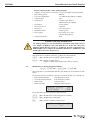
As a precaution, a confirmation messages asks if you really want to modify
the current parameters (and specifies the active interface):
IEEE
7.4.3
STD PAR ?
NO
YES
LDS1000 Controller Parameter Input
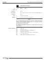
MAIN => CONF (F4) => RACK (F3)
7.4.3.1
Reading the Internal Software Version
MAIN => CONF (F4) => RACK (F3)
This menu displays the version of the LDS1000 software installed in the
controller.
This internal software manages all the controller’s functions, in manual
mode and in Interface Mode. It also operates the controller when analog
outputs are installed. The physical modification of the software is done by
EPROM exchange on the parent card of the 68000 processor.
Should you encounter any operating problems with the controller, this
information will be useful to the maintenance service. It is possible to
update the software as long as the material environment remains compatible with the working of the software.
Access to Menu Rack provides the following display:
LDS1000 V3.10
MAIN
NEXT
The following functions are active:
NEXT
(F4) Access to next parameter.
MAIN
(F5) Return to main menu.
25
EDH0170En1020 — 07/11
LDS1000
Controller for Laser Diode Sensors
7.4.3.2
Modification of Display Brightness
MAIN => CONF (F4) => RACK (F3) => NEXT (F4)
Four levels of brightness are available.
DISPLAY LIGHT
--+++
MAIN
NEXT
The following functions are active:
+++
(F3) Highest brightness.
---
(F2) Lower value.
NEXT
(F4) Next parameter.
MAIN
(F5) Return to main menu.
The maximum brightness is the default value.
7.4.3.3
Reading the Size of the Memory Installed
MAIN => CONF (F4) => RACK (F3) => NEXT (F4) => NEXT (F4)
The memory size depends on the option chosen at the time of ordering. It
is the size of the buffer memory used for automatic acquisitions carried out
by the LDS1000 Controller. This function is only accessible in Interface
Mode. The values read by the sensor can be successively stored in the
memory, at a high frequency.
MEM.
2048
MAIN
NEXT
The RS-232-C or IEEE-488 interface authorizes alternate reading of these values.
LDS1000 Controllers have a standard memory size of 2048 measurement
points (couples Y, Z). Approximately 1 second of measurement can be
stored at the maximum acquisition frequency of 2 kHz. The read-out time of
these values depends on the communication transmission speed and the
size of the host computer. For 2000 points, its value can reach several tens
of seconds.
The extended memory option offers an extended memory of 14336 points.
It enables an event to be stored in the memory the duration of which can
reach 7 seconds at 2 kHz.
The display of this menu directly gives the values of the memory size
expressed in the number of measurements that can be stored (one measurement is a couple of Y, Z values).
7.4.3.4
Reading the Analog Output Option
MAIN => CONF (F4) => RACK (F3) =>
NEXT (F4) => NEXT (F4) => NEXT (F4)
Only possible with controllers that have the analog output option.
ANALOG OUTPUT
MAIN
NEXT
The display of this menu shows whether this option is present on the controller concerned.
For more details on analog outputs, refr to the corresponding paragraph.
EDH0170En1020 — 07/11
26
LDS1000
8.0
Controller for Laser Diode Sensors
Analog Output Parameter Input
8.1
Selecting Analog Outputs (if option present)
MAIN => CONF (F4) => ANLG (F4)
The analog outputs are a material option that must be specified at the time
of ordering. They can be installed later on, but you will need to contact our
after-sales service.
When the analog outputs are activated, the OUTY and OUTZ connectors
located on the rear panel of the controller give two voltages that are proportional to the digital values calculated by the controller. The analog outputs take into account the real calibration performed on the current sensor
and provide the reliable values that can be used directly. The refresh frequency of the analog outputs has been set at 2 kHz which enables events to
be seized rapidly. Thus, when the analog outputs are active, the controller
no longer manages the display, or the communication with the computer.
When the analog outputs have been chosen and the controller is switched
off, the controller memorizes this status. When the controller is switched
on, the analog mode is reactivated. The LDS1000 Controller operates like a
standard analog instrument and can be perfectly integrated into classical
acquisition chains.
The configuration parameters of the analog outputs are the following:
INTG: Integration constant (in msec).
Like the digital version, the value available at the output is obtained by a
sliding average of a given number of values measured at maximum frequency. With this parameter a frequency filter adapted to the signals that you
wish to obtain can be selected.
GAIN: Choice of output gain.
The output voltage is between -10 volts and +10 volts. When the gain is 1,
the voltage of +10 V matches the highest limit of the measurement range.
When the gain is 10, the same voltage only corresponds to a tenth of the
highest limit of the measurement range.
With a gain of 1, the resolution of 1 increment supplies a voltage of 5 mV. It
increases to 50 mV for a gain of 10.
The ANLG (F4) menu provides access to the analog outputs that are
immediately available on the rear panel. In addition, it displays the current
parameters:
ANALOG OUTPUT
100 ms
Gx1
MAIN
CONF
The first value is the value of the integration constant used, the second
value is the value of the gain.
27
EDH0170En1020 — 07/11
LDS1000
Controller for Laser Diode Sensors
•
•
•
•
•
•
•
•
•
•
•
Electric Characteristics of the Analog Outputs:
Outputs on rear panel of controller 2 connectors BNC OUTY and OUTZ
Refresh frequency
2000 Hz
Low pass digital filter
1 to 2000 Hz (depending on INTG)
Output range
±10 V
Scale factor
5 mV/incr (for Gx1) to
1000 mV/incr (for Gx200)
Resolution
0.5 increment
Electronic noise
1 mV rms
Distortion
0.5% (electronic)
Maximum offset
50 mV typical
Discrepancy
Pure delay of 1.1 msec
(outside integration)
Output impedance
10 Ω
WARNING: SPECTRAL WITHDRAWAL
The analog outputs use an intermediary calculation stage that is based
on a sample at 2000 Hz. This will limit the use of the LDS sensor for
studying signals that do not have a significant spectral component over
1000 Hz (this sort of component would find themselves “withdrawn” and
would appear for lower frequencies).
The functions accessible by the ANLG Menu are the following:
8.2
CONF
(F4) Modification of analog output parameters.
MAIN
(F5) Return to main menu.
Return to main menu disables the analog outputs.
Modification of Analog Output Parameters
MAIN => CONF (F4) => ANLG (F4) => CONF (F4)
The integration constant INTG and the gain GAIN can be modified in this
menu.
They will be chosen in relation to the type of measurements to be carried out:
• Rapid measurements:
Low integration value.
• Accurate measurements:
Long integration value.
• Wide range:
Low gain value.
• Reduced range:
High gain value (Zoom).
ANALOG OUTPUT
INTG GAIN
END
CONF
From this menu the active keys are the following:
INTG
(F1) Modification of the integration constant.
GAIN
(F2) Modification of the gain.
END
(F5) Return to analog output mode.
INTG =
100 ms
--+++
EDH0170En1020 — 07/11
28
SET
LDS1000
Controller for Laser Diode Sensors
GAIN = x1
---
v
+++
SET
For each of the parameters, a modification menu uses the following functions:
---
(F2) Lower value.
+++
(F3) Next highest value.
SET
(F5) Save and Return to analog output mode.
List of parameters:
INTG
GAIN
Designation
Integration
constant (msec)
Output gain
Digital/Analog
Available Values
Default Value
0.5; 1; 2; 5; 10; 20;
100
50; 100; 200; 500; 1000
1; 2, 5; 10; 20; 50;
1
100; 200
NOTE
When you exit analog output mode after modifying the integration constant, the new value is also used to calculate the display of the controller.
Scale factors that correspond to the combined choice of the gain and the
counter increment.
Incr.
Gain
1
2
5
10
20
50
100
200
OUTY or OUTZ in mV for a Displayed Unit (µrad, sec, …)
0.1
0.2
0.5
1
2
5
10
20
50
50 mV
25 mV
10 mV 5 mV
2.5 mV 1 mV
0.5 mV 0.25 mV 0.1 mV
100 mV 50 mV
20 mV 10 mV 5 mV
2 mV 1 mV
0.5 mV 0.2 mV
250 mV 125 mV50 mV
25 mV 12.5 mV 5 mV
2.5 mV 1.25 mV 0.5 mV
500 mV 250 mV 100 mV50 mV
25 mV 10 mV 5 mV
2.5 mV 1 mV
1V
500 mV 200 mV 100 mV50 mV
20 mV 10 mV 5 mV
2 mV
2.5 V
1.25 V 500 mV 250 mV 125 mV50 mV
25 mV 12.5 mV 5 mV
5V
2.5 V
1V
500 mV 250 mV 100 mV50 mV
25 mV 10 mV
10 V
5V
2V
1V
500 mV 200 mV 100 mV50 mV
20 mV
OUT (mV) = Measure (unit) x Gain/Incr. x 5
Example: using the Table.
The controller operates in manual mode with a Yincr value of 0.2 and a unit
given in arc-sec. The following values can therefore be read:
Y=Z=
2.62 sec MENU
8.54 sec CONF
We can therefore expect to obtain the following analog values:
• With a gain of 1:
OUTY = - 2.62 x 25 = - 65.5 mV
OUTZ = 8.54 x 25 = 213.5 mV
• With a gain of 5:
OUTY = -2.62 x 125 mV = - 327.5 mV
OUTZ = 8.54 x 125 mV = 1067.5 mV
29
EDH0170En1020 — 07/11
LDS1000
9.0
Controller for Laser Diode Sensors
TRIG Input and PWOK Output
9.1
Conventions on Logical Inputs/Outputs
The controller has a logical TRIG input available on a BNC socket on the
rear panel.
It provides a logical PWOK output that indicates if the sensor is receiving
light.
TRIG
Input
PWOK
Output
Logical Inputs/Outputs.
• The convention retained for logical inputs/outputs is the following:
– ACTIVE = 1 = High Status = The current flows = Drawn at the ground.
– PASSIVE = 0 = Low Status = The current doesn’t flow = Open wire.
• The output (PWOK) is in High status (value 1) when the sensor receives
light. With the RO command it is possible to read the status of this output.
• The passage of the TRIG input from Low status to High status (upward
front) triggers the start of the synchronized acquisitions. With the RB
command it is possible to read the status of this input.
• The wiring of the logical PWOK output to the logical TRIG input allows
an acquisition cycle to be started when signal inputs into the measurement range of the sensor.
• Max. frequency PWOK: 130 Hz.
• Max. frequency TRIG: 500 Hz.
• The reading is performed with a random delay from 0 to 1 msec.
The logical inputs/outputs can only be used in Interface Mode.
EDH0170En1020 — 07/11
30
LDS1000
Controller for Laser Diode Sensors
9.2
TRIG Input
+5 V
10 kΩ
TRIG
Input
5V1
100 pF
• Compatible TTL input.
• Max. voltage 5 V.
9.3
PWOK Output
100 Ω
PWOK
Output
• Open collector output.
• Max. voltage 30 V.
• Max. current 20 mA.
31
EDH0170En1020 — 07/11
LDS1000
10.0
Controller for Laser Diode Sensors
Use with a Computer Interface
The LDS1000 electronic controller offers its full measuring capacity when
connected to a computer via an RS-232-C or IEEE-488 interface. Interface
Mode is activated by sending a computer message. It can only be activated
when:
• The physical connection between the controller and the computer is
correct.
• The controller interface parameters and those of the computer are compatible.
• The correct computer output is commanded.
• The controller is in the main menu when the connection is established.
Interface Mode allows:
• Flying spot reading of the measured values.
• Execution of synchronous acquisition sequences of a clock inside the
controller, or a logical external TRIG signal.
• Reading the sensor status and the I/O available.
The LDS1000 Controller is delivered with an RS-232-C cable. It will work for
example with a PC computer with the following minimum configuration:
• A PC computer.
• An RS-232-C or IEEE-488 interface (Hewlett Packard or National
Instrument card).
10.1
Checking the Interface
The controller must be connected to a calculator (RS-232-C or IEEE-488) or
a console (RS-232-C) via an adapted cable. Only connect the instruments
when everything is switched off.
WARNING
Before connecting, check that all equipment is switched off.
10.1.1
RS-232-C Interface
The LDS1000 Controller is delivered with an RS-232-C interface cable. This
cable has a male Sub-D25 connector for the controller connection (cf. diagram). When setting it up, make sure you tighten the support screws.
The other connector is a Sub-D9 pin plug compatible with the series output
of the computer. A Sub-D9/Sub-D25 pin adapter enables it to be linked to all
existing standards. It is useful to note the series output of the computer: it
is usually marked by one of the following: SERIAL, COM1, COM2, etc. (refer
to the computer documentation).
The communication must be obtained with a TERMINAL type program.
Read the software documentation to configure the parameters of the RS232-C output. It is recommended, as far as possible, to select the following
parameters, that are the LDS1000 Controller’s default parameters:
EDH0170En1020 — 07/11
32
LDS1000
Controller for Laser Diode Sensors
•
•
•
•
•
BAUD RATE
MSG TERM
WORD LENGTH
STOP BITS
PARITY
:
:
:
:
:
9600
CR
8
1
NONE
Start up the LDS1000 Controller and check, in Manual mode, the interface
parameters by selecting the RS-232-C protocol.
MAIN => CONF (F4) => COMM (F2)
If the display is:
REMOTE RS 232c MAIN
>>>
EDIT
STD
The RS-232-C interface is active (otherwise press the >>> (F1) key of the
controller to return to the RS-232-C protocol).
Use EDIT (F2) mode to visualize and modify the interface parameters if
necessary.
Return to the main display menu of the controller with the MAIN (F5) key.
The system is ready to communicate in RS-232-C.
RECOMMANDATION
Refer to the Appendix A: “Example of Program Using RS-232-C Link”.
10.1.2
IEEE-488 Interface
IEEE-488 interface is only possible if the computer is equipped with an IEEE488 communication card. Several models are available on the market.
RECOMMANDATION
NEWPORT recommends the National Instrument AT-GPIB/TNT card for
its software.
An IEEE-488 cable is required for the interface between the LDS1000
Controller and the IEEE-488 card. The cable is symmetrical and allows several instruments to be chained. This is the advantage of a parallel interface.
When setting up, make sure the support screws are properly tightened.
The communication must be obtained with a program. Read the software
documentation to configure the parameters of the IEEE-488 output. It is recommended, as far as possible, to select the following parameters, that are
the LDS1000 Controller’s default parameters:
• MSG TERM
: CR LF
• PRIM ADRESS
: 15
• SECOND ADRESS : 00
• TIME OUT
: 0.5 sec
The controller operates the IEEE-488 interface in SRQ mode: the controller
status can be read with the SPOL function of the IEEE-488 card. This status
is coded by an 8 bits word, bit 7 of which (value 128) is worth 1 if a message is near: The reading must always be carried out before a new request.
33
EDH0170En1020 — 07/11
LDS1000
Controller for Laser Diode Sensors
Start up the LDS1000 Controller and check, in manual mode, the interface
parameters by selecting the IEEE-488 protocol.
MAIN => CONF (F4) => COMM (F2)
If the display is:
REMOTE IEEE488 MAIN
>>>
EDIT
ST
The IEEE-488 interface is active. (Otherwise press the >>> (F1) key of the
controller to return to the IEEE-488 protocol)
Use EDIT (F2) mode to visualize and modify the interface parameters if
necessary.
Return to the main display menu of the controller.
The system is ready to communicate in IEEE-488.
RECOMMANDATION
Refer to the Appendix B: “IEEE-488 Link Characteristics”.
10.2
LDS-TOOLS Software
In order to communicate with the controller, the user must have a terminal
or a computer capable of communicating with external devices via a RS-232-C
or IEEE-488 interface.
One approach is to use a communications software that can emulate a terminal. An other solution is to use NEWPORT software, Windows 3.11, Windows
95 and Windows NT compatible, and delivered with the LDS1000
Controller.
You can install this software on a PC compatible computer with the following minimum configuration:
• A Personal Computer or compatible.
• A VGA monitor.
• An 80386 or later processor.
• 4 MB of available memory (8 MB recommended).
• A hard disk with enough disk space to install the options you need.
• A Windows™ 3.1x environment.
LDS-TOOLS only accepts the following interfaces:
• COM1 or COM2 standard serial port.
• HP-IB Hewlett-Packard® board, model HPIB 82335.
• HP-IB Hewlett-Packard® board, model HPIB 82340.
• GPIB National Instrument® board, model AT-GPIB/TNT.
ATTENTION
Before to use NEWPORT LDS Tools software, IEEE-488 boards (listed
above) must be into the initial configuration of the constructor, and
installed in accordance with its recommended procedure.
Before to use NEWPORT LDS Tools software, we advise you to use softwares utilities supplyed with the IEEE-488 board to check that the installation is completed successfully.
EDH0170En1020 — 07/11
34
LDS1000
Controller for Laser Diode Sensors
This software enables you to quickly master the instrument in Interface
Mode. You are able to promptly check if the communication is working correctly. It is a base for learning the basic functions of the LDS1000
Controller. Finally, it is used as a communication basis with LDS-Vector for
a substantial number of applications.
This software will only work with controllers that have a software version
higher than V3.00.
With the software the main functions of LDS instruments can be used:
• Display of the position by a moving spot on a target.
• Diameter of the variable target in relation to the spot position.
• Display of the position in large characters (Remote reading).
• Dialog with the controller, parameter modification.
• Point to point acquisition sequence, analysis and storage.
• Rapid acquisition sequence (max. freq. 2 kHz), analysis and storage.
10.3
Programming
Before we get to this chapter, we presume that the interface parameters
have been checked, and that the connection is established. The LDS-TOOLS
program is useful for checking the material configuration (refer to the previous chapters).
We will also presume that the first lines of the program contain adequate
parameter commands that enable the computer interface to be configured
in the mode chosen. The information on this point is contained:
• In the instructions for the programming software used (Basic instructions for example).
• In the manual of the computer used.
• Possibly in the instructions for the IEEE-488 card chosen.
Whichever protocol is used (RS-232-C or IEEE-488), the communication
logic with the LDS1000 Controller is the same.
35
EDH0170En1020 — 07/11
LDS1000
Controller for Laser Diode Sensors
The computer sends a chain of characters to the controller that may then:
• Respond with a return chain.
• Carry out a modification or a function (without necessarily responding).
• Not respond and not react (message is not recognized).
The communication software must be able to generate ASCII messages
(refer to syntax in the description of recognized commands).
It must also use a send command for this message on the current interface
(refer to syntax in the supplier’s instructions for the programming software).
It must then be able to read the return message or wait for this message
(refer to syntax in the supplier’s instructions for the programming software).
Finally, the message must be interpreted and the information contained in
the chain of characters received must be recognized (values measured,
sensor status, various parameters, …).
A properly structured program will include sub-programs that carry out
these basic functions. Be particularly careful when writing these modules
that are essential for the proper operating of the final program.
In all cases:
• The first order to be sent to the controller is the MR command that activates the controller in Interface Mode.
• If the communication is correct, the controller displays:
LDS1000 CONTROLLER
REMOTE
MODE
In other cases, check that:
• The controller is switched on.
• It is working in Main menu (if not cf. manual mode).
• The physical connection is correct.
• The communication parameters are correct.
• The syntax sent is correct.
• The initialization of the interface is properly carried out.
The reading sub-program should then be tested using, for example, the VE
command which requests the software version of the LDS1000 Controller.
The response must be an ACSII chain of type:
VE LDS1000 CONTROLLER VERSION 3.0
If their is no response, carefully check the structure of the reading sub-program.
10.3.1
Structure of Messages to the Controller
The ASCII chains transmitted by the computer must match the commands
understood by the LDS1000 Controller. Each message transmitted may
include several different commands, separated by commas (,) or semicolons (;) and will end with the appropriate character (CR, LF, CRLF, LFCR).
The <space> characters will be deleted on reception.
EDH0170En1020 — 07/11
36
LDS1000
Controller for Laser Diode Sensors
The core of each command is made up of two letters. For example:
MR: Set remote mode.
The parameters associated with the command are:
• Either the full digital values, preceding the command core. They usually
indicate the address (or the number) where the information should be
looked for. For example:
42TT: Reading the measurement number 42.
• Or the decimal digital values, using a separating dot (.), according to the
central core. They correspond to a value transmitted to the controller
to modify the parameter concerned. For example:
TM152: Launch the acquisition of 152 measurements.
The commands received by the controller are stored in a communication
buffer of 255 characters. The controller carries them out chronologically by
emptying this buffer memory.
The ASCII chains transmitted from the controller to the computer are the
following:
• Generally they start by copying a part of the message sent.
• They are followed by the value or values of the response parameter.
• Commas are used to separate (,).
For example, when the 1TP command is sent which requests the value
measured on axis 1, the controller returns the chain:
1TP-1596.3 which indicates that the value measured on axis 1 is -1596.3.
Certain commands do not generate return from the LDS1000 Controller. For
example, the SP50 command that sets the sampling period at 50 msec.
Incorrect commands create an error. Only the last error code is stored in
the memory. This code will be reset at @ (no error) when it is read again.
In every case, to find out whether the command has been correctly performed, test the status of the controller using the TB command (Reading
the error).
The list of commands recognized by the LDS1000 Controller are given later
in this manual. You are advised to read the description of a command carefully before using it.
10.3.2
Programming Conventions
• Access to Interface Mode is only driven by the computer (MR command).
• Access to Interface Mode is only possible if the controller is in its main
menu.
• When the controller is in Interface Mode, none of the keys on the front
panel are valid.
• The axes called Y and Z on the display correspond respectively to numbers 1 and 2 of the Interface Mode commands.
• The result matrices are numbered starting at 1. The first value in the
memory is marked value 1.
• The measurements transmitted by the controller have the same format
as the values displayed. They take into account the units used for the
selected sensor.
• The Interface Mode output is activated by computer (ML command).
37
EDH0170En1020 — 07/11
LDS1000
EDH0170En1020 — 07/11
Controller for Laser Diode Sensors
10.4
List of Commands
10.4.1
Commands Listed by Category
10.4.1.1
System Management
Command
Description
ML
Set Manual mode.
MR
Set Interface Mode.
RD
Frozen display.
RE
Active display.
RS
Reset system.
TB
Read error.
TE
Read error code.
TS
Read operational status.
VE
Read Soft version.
10.4.1.2
Reading Current Sensor Parameters
Command
Description
TA
Read current sensor parameters.
TN
Reading sensor number and series number.
10.4.1.3
Classical Acquisitions
Command
Description
KI
Define the integration constant.
TP
Read current measurement.
XI
Read integration constant.
10.4.1.4
Dynamic Acquisitions
Command
Description
MS
Read acquisition status.
SP
Define sample period
ST
Stop current acquisitions.
TK
Acquisitions with trigger on TRIG input.
TM
Immediate acquisitions.
TQ
Acquisitions with synchronization on TRIG input.
TT
Re-read acquisitions.
XN
Read number of measurements in memory.
XS
Read sample period.
10.4.1.5
Reading Logical Inputs/Outputs
Command
Description
RB
Read TRIGG input status.
RO
Read PWOK output status.
38
LDS1000
Controller for Laser Diode Sensors
10.4.2
Commands Listed in Alphabetic Order
Command
Description
KI
Define the integration constant.
ML
Set Manual mode.
MR
Set Interface Mode.
MS
Read acquisition status.
RB
Read TRIGG input status.
RD
Frozen display.
RE
Active display.
RO
Read PWOK output status.
RS
Reset system.
SP
Define sample period.
ST
Stop current acquisitions.
TA
Read current sensor parameters.
TB
Read error.
TE
Read error code.
TK
Acquisitions with trigger on TRIGG input.
TM
Immediate acquisitions.
TN
Read sensor number and series number.
TP
Read current measurement.
TQ
Acquisitions with synchronization on TRIGG input.
TS
Read operational status.
TT
Proof read acquisitions.
VE
Read software version.
XI
Read integration constant.
XN
Number of measurements in memory.
XS
Read sample period.
10.5
Description of Commands
The rest of the manual presents the commands recognized in Interface
Mode by the LDS1000 Controller. The format of one page per command is
used to make it easier to look for the correct syntax.
The commands are listed in alphabetic order.
For each command, you will find the following information:
• The modes in which the following can be carried out (if not => error D):
MNL for manual mode.
RMT for remote mode (or Interface Mode).
ACT for active (acquisition in progress).
• Its syntax.
• Its parameters and the errors if they are incorrect.
• Its description.
• Its response.
• The related errors.
• An example.
• A comment if necessary.
• The commands related to that command.
39
EDH0170En1020 — 07/11
LDS1000
Controller for Laser Diode Sensors
10.5.01
KI
Use
Syntax
Parameter
MNL
nn
ACT
0; 1; 2; 5; 10; 20; 50; 100; 200; 500; 1000.
Integration constant in msec with 0 = no integration
=>0.5 msec).
Possible error
nn other than list below: nn takes nearest value.
Set the value of the integration constant INTG to nn msec.
Response
Example
RMT
KInn
Description
Error
Define the Integration Constant
None.
D
KI100
Execution not allowed.
| Define integration constant at 100 msec.
NOTE
Do not confuse KI integration constant, and SP sample period.
The integration constant KI sets the duration of the digital averaging carried out on acquisitions to 2 kHz.
The sample period SP sets the time interval separating two successive
measurements (related to commands TK, TM).
Related commands
EDH0170En1020 — 07/11
SP
TB
TE
XI
Define sample period.
Read error.
Read error code.
Read integration constant.
40
LDS1000
Controller for Laser Diode Sensors
10.5.02
ML
Use
Syntax
MNL
ACT
None.
Description
End of remote mode and return to manual mode.
Response
Example
RMT
ML
Parameter
Error
Return to Local Mode
None.
D
ML
Execution not allowed.
| Return to manual mode.
NOTES
When returning from Interface Mode to Manual mode, the display
returns to the Main menu, the keys on the front panel are active again,
and the integration constant keeps the value possibly programmed by KI.
The parameters SP, TE, XN are set at the following values:
SP = 0, TE = @ and XN = 0.
Related commands
MR
RD
RE
TB
TE
Set Interface Mode.
Frozen display.
Active display.
Read error.
Read error code.
41
EDH0170En1020 — 07/11
LDS1000
Controller for Laser Diode Sensors
10.5.03
MR
Use
Syntax
MNL
ACT
None.
Description
Set Interface Mode from Manual mode (manual mode in main
menu).
Response
Example
RMT
MR
Parameter
Error
Set Interface Mode
None.
D
MR
Execution not allowed.
| Set Interface Mode.
REMARQUE
The controller then displays LDS1000 REMOTE MODE.
Related commands
EDH0170En1020 — 07/11
ML
RD
RE
TB
TE
Set manual mode.
Frozen display.
Active display.
Read error.
Read error code.
42
LDS1000
Controller for Laser Diode Sensors
10.5.04
MS
Use
Syntax
MNL
Example
Related commands
ACT
None.
Description
Errors
RMT
MS
Parameter
Response
Read Acquisition Status
Read acquisition status. The return value is an ASCII character
the code of which should be translated into binary.
• Bit 0 = 0 : Correct power received.
= 1 : Incorrect power received.
• Bit 1 = 0 : Correct position.
= 1 : Incorrect position.
• Bit 2 = 0 : Acquisition not started up.
= 1 : Acquisition started up - TRIGG wait.
• Bit 3 = 0 : No acquisition in progress.
= 1 : Acquisition in progress.
• Bit 4 = 0
• Bit 5 = 0
• Bit 6 = 1
• Bit 7 = 0
MSaa
aa is an ASCII character.
D
S
Execution not allowed.
Communication time-out.
MS
MS@
TB
TE
| Read acquisition status.
| System resting.
Read error.
Read error code.
43
EDH0170En1020 — 07/11
LDS1000
Controller for Laser Diode Sensors
10.5.05
RB
Use
Syntax
MNL
Example
Related commands
10.5.06
Read the status of the TRIGG input. The return value will be
equal to 0 or 1 depending on whether the interface is in high
status or low status.
RBnn
nn = status of TRIGG input.
D
S
Execution not allowed.
Communication time-out.
RB
RB1
| Request status of TRIGG input.
| TRIGG input is in high status.
RO
TB
TE
Read PWOK output status.
Read error.
Read error code.
RD
Use
Syntax
MNL
RMT
ACT
None.
Description
Freezes the display on “REMOTE MODE” instruction to remove
response times related to the display refresh.
This is the default display mode for Interface Mode.
Response
Example
Set Frozen Display Mode
RD
Parameter
Error
ACT
None.
Description
Errors
RMT
RB
Parameter
Response
Read TRIGG Input Status
None.
D
RD
Execution not allowed.
| Frozen display. The controller displays:
LDS1000 CONTROLLER
REMOTE
MODE
Related commands
EDH0170En1020 — 07/11
RE
TB
TE
Active display.
Read error.
Read error code.
44
LDS1000
Controller for Laser Diode Sensors
10.5.07
RE
Use
Syntax
MNL
Enable display in remote mode. The response times related to
display refresh may appear.
Response
None.
D
Example
RE
Related commands
RD
TB
TE
RO
Use
Syntax
MNL
Example
| Active display.
Frozen display.
Read error.
Read error code.
Read PWOK Output Status
RMT
ACT
None.
Description
Errors
Execution not allowed.
RO
Parameter
Response
ACT
None.
Description
10.5.08
RMT
RE
Parameter
Error
Set Active Display Mode
Read the status of the PWOK output. The return value will be
equal to 0 or 1 depending on whether the interface is in high or
low status.
ROnn
nn = status of the PWOK output.
D
S
Execution not allowed.
Communication time-out.
RO
RO0
| Request status of TRIGG input.
| The PWOK output is in low status.
NOTE
The PWOK output is in status 1 if the sensor receives a sufficient quantity
of light to carry out the measurement.
This logical output is available on the rear panel of the LDS1000 Controller.
Related commands
TB
TE
Read error.
Read error code.
45
EDH0170En1020 — 07/11
LDS1000
Controller for Laser Diode Sensors
10.5.09
RS
Use
Syntax
MNL
Stop work in progress and carry out a RESET on the LDS1000
electronic controller.
Response
None.
D
Execution not allowed.
Example
RS
Related commands
TB
TE
10.5.10
SP
Syntax
Parameter
MNL
nn
Related commands
EDH0170En1020 — 07/11
Read error.
Read error code.
Define Sample Period
RMT
ACT
Sample period in milliseconds.
nn = 0.5 to 32000 msec, by steps of 0.5 msec.
Possible errors
nn absent + nn = 0.5 msec.
nn off limits + nn = Nearest authorized value.
Sets the sample period to nn milliseconds for TM and TK functions.
Response
Example
| Reset system.
SPnn
Description
Error
ACT
None.
Description
Use
RMT
RS
Parameter
Error
Reset System
None.
D
SP50
TB
TE
TK
TM
Execution not allowed.
| Set the sample period to 50 msec.
Read error.
Read error code.
Acquisitions with trigger on TRIGG input.
Immediate acquisitions.
46
LDS1000
Controller for Laser Diode Sensors
10.5.11
ST
Use
Syntax
MNL
ACT
None.
Description
Stop work in progress (acquisition launched by TK, TM or TQ).
Response
Example
RMT
ST
Parameter
Error
Stop Work in Progress
None.
D
ST
Execution not allowed.
| Stop the work in progress and carry on.
NOTE
The ST command stops the acquisitions in progress without deleting the
memory. The measurements performed up to receiving this command
are stored in the controller’s memory.
The XN parameter keeps its value.
The command xxTT makes it possible to read the values stored if xx is
lower than XN.
Related commands
TB
TE
TK
TM
TQ
TT
XN
Read error.
Read error code.
Acquisitions with trigger on TRIGG input.
Immediate acquisitions.
Acquisitions with synchronization on TRIGG input.
Proof read acquisitions.
Read number of measurements in memory.
47
EDH0170En1020 — 07/11
LDS1000
Controller for Laser Diode Sensors
10.5.12
TA
Use
Syntax
Parameter
MNL
xx
Related commands
10.5.13
Syntax
Parameter
B
D
S
1TA
TB
TE
MNL
Errors
aa
EDH0170En1020 — 07/11
| Read the parameters of axis 1 (Y) of the current sensor.
Read error.
Read error code.
Error Description
RMT
ACT
Error code in ASCII format (@ to U).
If there is no parameter + read current error.
Read message related to a an error code (parameter aa). Read
current error message if aa is missing.
TBaabb
aa = Error code queried.
bb = Error description.
D
S
Execution not allowed.
Communication time-out.
Example TB@
TB@ No error
Related command
Incorrect axis number.
Execution not allowed.
Communication time-out.
TBaa
Description
Response
Axis number: 1 for Y and 2 for Z.
Possible errors
xx ≠ 1 and xx ≠ 2 + Error B.
Sensor axis parameters.
TB
Use
ACT
Read parameters of a current sensor axis:
TYPE : RT or TR.
COEF : 00100 to 29999.
INCR : 0,1; 0,2; 0,5; 1; 2; 5; 10; 20; 50.
UNIT : µrad; sec; mrad; nm; µm; mm; unit.
OFS1 : 00000 to 32767.
OFS2 : 00000 to 32767.
The parameters are separated by commas.
Response
Example
RMT
xxTA
Description
Errors
Query Sensor Parameters
TE
| Read error message @.
| No error.
Read error code.
48
LDS1000
Controller for Laser Diode Sensors
10.5.14
TE
Use
Syntax
MNL
Example
Related command
ACT
None.
Description
Errors
RMT
TE
Parameter
Response
Read Error Code
Read last error code generated by the LDS1000 Controller:
ASCII character stored in error register.
The error register is reset when read with TB or TE.
Only the last error encountered can be read again.
TEaa
aa = Current Error Code.
Error messages:
@
: No error.
A
: Unknown message code.
B
: Incorect axis number.
C
: Parameters out of limits.
D
: Execution not allowed.
O
: Variable is out of range.
S
: Communication time-out.
D
S
Execution not allowed.
Communication time-out.
TE
TE@
TB
| Read error code.
| No error.
Read error.
49
EDH0170En1020 — 07/11
LDS1000
Controller for Laser Diode Sensors
10.5.15
TK
Use
Syntax
Parameters
MNL
nn
Description
ACT
1 at NBMAX. Number of measurements to be performed
(NBMAX = Max. number of measurements related to the memory installed).
Possible error
nn outside authorized interval + Error C.
1 to nn. Number of the measurement synchronized on trigger
pulse (TRIGG input).
Possible error
nn outside authorized interval + Error O.
Performs an acquisition of nn measurements, as the measurement xx is synchronous with the trigger signal (the acquisitions are stored in a revolving memory of xx values while
awaiting trigger signal).
The acquisition period is given by SP.
The integration constant set by KI is used.
The number of the acquisition in progress is given by XN.
XN remains equal to zero while the trigger signal is absent,
then Xn directly takes the value xx.
If the trigger signal arrives before xx measurements are stored
in the memory, the first values will be set at MIN, MIN being
the lowest limit of the measurement range of the sensor used.
Response
Example
RMT
xxTKnn
xx
Errors
Acquisition on External Trigger
None.
C
D
O
Parameter out of limit.
Execution not allowed.
Variable is out off range.
20TK100 | Pre-launch the acquisition of a series of 100 measurements.
Measurements 1 to 19 precede the trigger signal, measurement 20
is synchronous with this signal and measurements 21 to 100
come after it.
NOTE
The trigger signal is an external logical signal, that must be connected to
the TRIG input located on the rear panel of the LDS1000 Controller.
Related commands
EDH0170En1020 — 07/11
KI
TB
TE
SP
XN
Define the integration constant.
Read error.
Read error code.
Define sample period.
Read number of measurements in memory.
50
LDS1000
Controller for Laser Diode Sensors
10.5.16
TM
Use
Syntax
Parameter
MNL
nn
Related commands
10.5.17
Syntax
C
D
TM100
KI
TB
TE
SP
XN
MNL
Define the integration constant.
Read error.
Read error code.
Define sample period.
Read number of measurements in memory.
Read Number of Selected Sensor
RMT
ACT
Read number of sensor selected by the user.
TNxx,yy
xx is the number of the selected sensor (0 to 9).
yy is its series number.
D
S
Execution not allowed.
Communication time-out.
Example TN
TN5,151232
Related commands
| Launch the acquisition of a series of 100 measurements.
None.
Description
Errors
Parameter out of limit.
Execution not allowed.
TN
Parameter
Response
1 at NBMAX. Number of measurements to be performed
(NBMAX = Max. number of measurements related to the memory installed).
Error possible
nn outside authorized interval + Error C
None.
TN
Use
ACT
Immediately carries out an acquisition of nn successive measurements.
The acquisition period is given by SP.
The integration constant set by KI is used.
The number of the acquisition in progress is given by XN.
XN is equal to nn when the series of acquisitions is finished.
Response
Example
RMT
TMnn
Description
Errors
Immediate Acquisition
TB
TE
| Request the number of the sensor selected.
| Sensor number 5 is selected, its series number is 151232.
Read error.
Read error code.
51
EDH0170En1020 — 07/11
LDS1000
Controller for Laser Diode Sensors
10.5.18
TP
Use
Syntax
Parameter
MNL
Errors
xx
10.5.19
Syntax
Parameter
D
S
TB
TE
MNL
nn
| Request position.
| Y = 4.5 and Z = 1254.6.
Read error.
Read error code.
Acquisition on External Signal
RMT
ACT
1 at NBMAX: number of measurements to be performed
(NBMAX = max. number of measurements related to the memory installed).
Possible error
nn outside authorized interval + Error C
Performs an acquisition of nn measurements triggered by an
external signal wired to the TRIGG input (active on upward front).
The integration constant set by KI is used.
The number of the acquisition in progress is given by XN.
Response
Example
Execution not allowed.
Communication time-out.
TQnn
Description
Errors
Number of axis to be read (xx = 1 for Y and xx = 2 for Z).
xx missing or xx ≠ 1 and xx ≠ 2 + Read two axes.
xxTPnn
or
1TPnn1,2TPnn2
TQ
Use
ACT
Read current position.
Example TP
1TP4.5,2TP1254.6
Related commands
RMT
xxTP
Description
Response
Read Current Position
None.
C
D
TQ10
Parameter out of limit.
Execution not allowed.
| Launch the acquisition of 10 measurements triggered by an external (TRIGG input).
NOTE
This external input can be a simple push button without rebound, which
enables the operator to carry out the measurements at the most appropriate moment.
EDH0170En1020 — 07/11
52
LDS1000
Controller for Laser Diode Sensors
Related commands
KI
TB
TE
TK
XN
10.5.20
TS
Use
Syntax
MNL
Example
Related commands
RMT
ACT
None.
Description
Errors
Read Operational Status
TS
Parameter
Response
Define the integration constant.
Read error.
Read error code.
Acquisitions with trigger on TRIGG input.
Read number of measurements in the memory.
Read acquisition status. The return value is an ASCII character
the code of which should be translated into binary:
• Bit 0 = 0 : Standard memory.
= 1 : Extended memory.
• Bit 1 = 0 : Frozen display mode.
= 1 : Refreshed display mode.
• Bit 2 = 0
• Bit 3 = 0
• Bit 4 = 0
• Bit 5 = 0
• Bit 6 = 1
• Bit 7 = 0
Table for reading messages received:
@
: Standard memory (2048) and frozen display.
B
: Standard memory(2048) and active display.
A
: Extended memory (14336) and frozen display.
C
: Extended memory(14336) and active display.
TSaa
aa is an ASCII character.
D
S
Execution not allowed.
Communication time-out.
TS
TS@
TB
TE
| Read operational status.
| Standard memory and frozen display.
Read error.
Read error code.
53
EDH0170En1020 — 07/11
LDS1000
Controller for Laser Diode Sensors
10.5.21
TT
Use
Syntax
Parameter
MNL
Errors
xx
EDH0170En1020 — 07/11
ACT
Number of the acquisition to be proof read.
xx = 0 to MAX (MAX = value returned by XN).
Possible error
xx missing + xx = 0.
xx outside authorized interval + Error C.
This command enables the measurements saved to be read
again following a TK, TM or TQ command.
If xx is a whole number other than nil within the authorized
interval, the controller returns the value of the measurement
xx. If xx = 0 or absent, the controller returns all the measurements in the memory (one measurement Y, Z per line starting
with the number 1).
In RS-232-C mode there is a 25-msec pause between two successive lines (response at TT or 0TT) to avoid overflow.
Reading is possible as soon as the acquisitions have begun.
xxTT,1TPnn1,2TPnn2
C
D
S
Example 9TT
9TT,1TP12.2,2TP258.1
Related commands
RMT
xxTT
Description
Response
Read Measurements Saved
TB
TE
Parameter out of limit.
Execution not allowed.
Communication time-out.
| Read measurement number 9.
| Measurement number 9: Y = 12.2 and Z = 258.1.
Read error.
Read error code.
54
LDS1000
Controller for Laser Diode Sensors
10.5.22
VE
Use
Syntax
MNL
Read internal program version of the controller.
VE LDS1000 Controller Version xx.yy
xx = Version.
yy = Progress index.
D
S
Execution not allowed.
Communication time-out.
Example VE
VE LDS1000 Controller Version 3.10
Related commands
TB
TE
10.5.23
XI
Use
Syntax
MNL
Example
Related commands
Read error.
Read error code.
Read Integration Constant
RMT
ACT
None.
Description
Errors
| Read program version.
| Program version 3.10.
XI
Parameter
Response
ACT
None.
Description
Errors
RMT
VE
Parameter
Response
Read Internal Program Version
Read integration constant given in milliseconds.
XInn
nn is the integration constant given in milliseconds.
D
S
Execution not allowed.
Communication time-out.
XI
XI100
KI
TB
TE
| Read integration constant.
| The integration constant is equal to 100 msec.
Define the integration constant.
Read error.
Read error code.
55
EDH0170En1020 — 07/11
LDS1000
Controller for Laser Diode Sensors
10.5.24
XN
Use
Syntax
MNL
Example
Related commands
Read number of measurements available in the memory.
XNnn
The memory contains nn measurements.
D
S
Execution not allowed.
Communication time-out.
XN
XN100
TB
TE
TK
TM
TQ
TT
10.5.25
XS
Use
Syntax
MNL
Example
Related commands
EDH0170En1020 — 07/11
Read error.
Read error code.
Acquisitions with trigger on TRIGG input.
Immediate acquisitions.
Acquisitions with synchronization on TRIGG input.
Re-read acquisitions.
Read Sample Period
RMT
ACT
None.
Description
Errors
| Read number of available measurements.
| The memory contains 100 measurements.
XS
Parameter
Response
ACT
None.
Description
Errors
RMT
XN
Parameter
Response
Read Number of Stored Measurements
Read sample period.
XSnn
The sample period is nn milliseconds.
D
S
Execution not allowed.
Communication time-out.
XS
XS2.5
TB
TE
SP
| Read sample period.
| The sample period is equal to 2.5 ms (400 Hz).
Read error.
Read error code.
Define sample period.
56
LDS1000
Controller for Laser Diode Sensors
10.6
Error Messages
Error messages are available in a specific memory of the LDS1000
Controller, in reply to the TE or TB message sent by the interface.
Character
@
A
B
C
D
O
S
Description
No error.
Unknown message code.
Incorect axis number.
Parameters out of limits.
Execution not allowed.
Variable is out of range.
Communication time-out.
Reading the error message resets the error memory to @.
10.7
Examples of Messages
The chain transmitted can be the second part of a command separated by
a comma or a semi-colon.
KI100;SP1000;TM100
Acquisition of 100 points with a period of 1000 msec and an integration
constant of 100 msec.
KI0;SP5;10TK100
Acquisition of 100 points with a period of 5 msec without integration. The
acquisition is synchronized on the TRIGG input so that the measurement
number 10 is synchronous with the setting to high status of this input.
KI1000;TQ100
Acquisition of 100 points with an integration constant of 1000 msec. Each
acquisition is triggered by setting the TRIGG input from 0 to 1.
10.8
Examples of Programs (Quick Basic by Microsoft)
10.8.1
Example with RS-232-C Interface
The RS-232-C interface is used to connect the LDS1000 Controller to a computer or a console.
The controller manages the RS-232-C interface like a three-wire interface:
only the send and receive lines are used as well as the mass.
This controller manages all the interface parameters that must be set at the
same values for the LDS and the computer (refer to the configuration chapter).
The following parameters are selected by default:
: 9600
• BAUD RATE
• MSG TERM
: CR
• WORD LENGTH : 8
• STOP BITS
: 1
• PARITY
: NONE
A higher rate can be obtained with BAUD RATE = 19200 if the computer can
bear it.
The CR terminator is the basic default terminator.
57
EDH0170En1020 — 07/11
LDS1000
Controller for Laser Diode Sensors
The example program “LDSRS1” is an example of programming in Quick
basic Microsoft.
It demonstrates how to:
• Open the interface with the appropriate parameters.
• Set the controller to remote mode.
• Send a command and wait for the response.
• Read the response and convert the ASCII chain received into digital values.
• Return to local mode.
RECOMMANDATION
Refer to the Appendix A: “Example of Program Using RS-232-C Link”.
10.8.2
Example with IEEE-488 Interface
Contrary to the RS-232-C interface, the IEEE-488 interface does not equip
computers in standard state.
This interface requires a special card that is included in the computer.
This card is supplied with library of functions that must be chained with
the program developed.
Refer to the card documentation to correctly perform the material configuration [IEEE-488 card/Computer].
Three program parameters must be related between the controller and the
computer:
: MSG TERM (CR LF by default).
• Chain terminator
• Primary address
: PRIM ADRESS (00 by default).
• Secondary address
: SECOND ADRESS (15 by default).
The CR LF terminator is the default terminator of the IEEE-488 card.
The controller manages the IEEE-488 interface in SRQ mode: the SPOL function of the IEEE card enables the controller status to be read. This status is
coded in one word of 8 bits, bit 6 of which(value 64) is worth 1 if a message
is near: reading must always by done before a new request.
RECOMMANDATION
Refer to the Appendix B3: “SRQ Using”.
EDH0170En1020 — 07/11
58
LDS1000
11.0
Controller for Laser Diode Sensors
Maintenance
11.1
Optical Head
CAUTION: LASER SAFETY
LDS Series Sensors are CLASS II LASER INSTRUMENTS according to the
EN 60825-1 standard:
DO NOT STARE INTO BEAM
Max. Power <1 mW @ 670 nm
RAYONNEMENT LASER
NE PAS REGARDER DANS LE FAISCEAU
ATTENTION RAYONNEMENT LASER
EN CAS D'OUVERTURE, EXPOSITION
DANGEREUSE AU FAISCEAU
LASER RADIATION
DO NOT STARE INTO BEAM
APPAREIL A LASER DE CLASSE 2
CLASS II LASER PRODUCT
DANGER. LASER RADIATION
WHEN OPEN, AVOID
DIRECT EXPOSURE TO BEAM
P <1 mW; λ = 670 nm
IEC60825-1
Device
Manufacturer:
LDS1000
1, Rue Jules Guesde, Bât B
ZI. Bois de l’épine
BP189 EVRY 914006 FR
S/N:
Manufactured: 06/2011
Complies with CFR 21 Subchapter J
Any other intervention requiring dismantling of all or part of the equipment
must be carried out by our maintenance service.
11.2
Maintenance of the LDS1000 Electronic Controller
WARNING
Certain safety precautions must be respected before any intervention on
the LDS1000 Controller.
In order to comply with the safety standards for the use of this equipment, the user must take the necessary precautions and respect the
warnings that appear in the chapter entitled “Warnings”.
The LDS1000 electronic controller is designed to receive signals from an
LDS-Vector autocollimator. The following precaution are necessary if it is
to work correctly:
• Make sure that the mains current matches the characteristics of the
autocollimator.
• Make sure that the mains plug is grounded.
• Do not cause a short-circuit between the connector terminals of the
communication.
• Use the cables supplied by NEWPORT.
• Cut the power supply to the controller when making a connection.
• Do not connect the BNC terminals of the logical inputs/outputs to an
electric power supply.
• Do not try to connect a sensor other than the one supplied by
NEWPORT.
Maintenance
Clean the electronic controller with a soft cloth and a little alcohol while
powered off.
59
EDH0170En1020 — 07/11
LDS1000
Controller for Laser Diode Sensors
11.3
Cables
SENSOR
CONNECTOR
Y&Z
OUTPUTS
TRIG
INPUT
11.3.1
IEEE-488
PWOK
OUTPUT
RS-232-C
RS-232-C Cables
WARNING
Use a standard commercial cable, or the cable supplied with the
DLS1000 Controller (sheathed cable that is <3 meters in length).
LDS1000
Computer
Sub-D25 male
Sub-D9 femal
2 (TxD) ...................................3 (TxD)
3 (RxD) ...................................2 (RxD)
7 (GND) ..................................5 (GND)
or
LDS1000
Computer
Sub-D25 male
Sub-D25 femal
2 (TxD) ...................................2 (TxD)
3 (RxD) ...................................3 (RxD)
7 (GND) ..................................7 (GND)
11.3.2
IEEE-488 Cable
WARNING
Use a standard commercial cable.
EDH0170En1020 — 07/11
60
LDS1000
Controller for Laser Diode Sensors
11.3.3
Sensor Interface Cable: “SENSOR” Connector
WARNING
Only use the cable supplied with the NEWPORT LDS-Vector.
11.3.4
Analog Output Cables: “OUT Y” & “OUT Z” Connectors
WARNING
Use sheathed commercial cables that are <3 meters in length.
11.3.5
Measurement Synchronization Input Cable: “TRIG” Connector
WARNING
Use sheathed commercial cable that is <3 meters in length.
11.3.6
Beam Signal Output Cable: “PWOK” Connector
WARNING
Use sheathed commercial cable that is <3 meters in length.
61
EDH0170En1020 — 07/11
LDS1000
12
Controller for Laser Diode Sensors
Appendices
A
Example of Program Using RS-232-C Link
'LDS1000 EXAMPLE SOFTWARE, Microsoft Quick Basic V4.5
CLS
'initialisations RS-232 COM 1 with standard parameters
CHAINE$ = "COM1:9600,N,8,1,CS,DS,CD,OP3000"
OPEN CHAINE$ FOR RANDOM AS #1
'LDS1000 in remode remote
ev$ = "MR"
PRINT #1, ev$
'Example: Loop on Position Reading
env$ = "TP"
LOCATE 5, 10: PRINT "LAERS1 exemple software "
LOCATE 18, 10: PRINT "Hit any key to abort "
WHILE INKEY$ = ""
' send TP
PRINT #1, env$
' wait answer
WHILE LOC(1) = 0: WEND
' read LA510 answer
LINE INPUT #1, ret$
' conversion ASCII => numerical values
msge$ = MID$(ret$, 4)
comma = INSTR(msge$, ",")
posy$ = LEFT$(msge$, comma - 1)
posz$ = MID$(msge$, comma + 4)
posyn = VAL(posy$)
poszn = VAL(posz$)
' print result
LOCATE 10, 10: PRINT "LAE510 message: "; ret$
LOCATE 12, 20: PRINT " Y value: ";
LOCATE 12, 30: PRINT USING "+######.##"; posyn
LOCATE 13, 20: PRINT " Z value: ";
LOCATE 13, 30: PRINT USING "+######.##"; poszn
WEND
'LDS1000 in local mode
ev$ = "ML"
PRINT #1, ev$
END
EDH0170En1020 — 07/11
62
LDS1000
Controller for Laser Diode Sensors
B
IEEE-488 Link Characteristics
NOTE
In order to meet FCC emission limits for a Class B device, you must use a
double shielded IEEE-488 cable. Operating this equipment with a single
shielded cable may cause interference to radio and television reception
in residential areas.
NOTE
Comply to IEEE Standard Digital Interface for Programmable
Instrumentation.
ANSI/IEEE Std. 488 - 1978. This norm is commonly called IEEE-488.
B.1
IEEE-488 Functions Supported by LDS1000 Controller
Mnemonic
ATN
DCL
EOI
EOL
GET
GTL
IFC
LAD
LLO
OSA
PPC
PPD
PPE
PPU
REN
SDC
SPD
SPE
SRQ
TAD
TCT
UNL
UNT
Definition
Attention
Device Clear
End or Identify
End of Line
Group Execute Trigger
Go to Local
Interface Clear
Listen Address
Local Lockout
Other Secondary Address
Parallel Pol Configure
Parallel Poll Disable
Parallel Poll Enable
Parallel Poll Unconfigure
Remote Enable
Selected Device Clear
Serial Poll Disable
Serial Poll Enable
Service Request
Talk Address
Take Control
Unlisten
Untalk
63
Support
Yes
Yes
Yes
Yes
No
No
Yes
Yes
No
No
No
No
No
No
No
Yes
No
Yes
Yes
Yes
No
Yes
Yes
EDH0170En1020 — 07/11
LDS1000
Controller for Laser Diode Sensors
B.2
IEEE-488 Function Subsets
This controller support the many GPIB function subsets, as listed bellow.
Some of the listings described subsets that the controller does not support.
C0 (Controller). The LDS1000 can not control other devices.
T5 (Talker). The LDS1000 becomes a Talker when the CIC (Controller In
Charge) sends its TAD (Talker Address) with the ATN (Attention) line
asserted. It ceases to be a talker when the CIC (Controller In Charge) sends
another device’s TAD (Talker Address) with ATN (Attention) asserted.
L4 (Listener). The LDS1000 becomes Listener when the CIC (Controller In
Charge) sends its LAD (Listener Address) with the ATN line asserted. The
LDS1000 does not have Listen Only capability.
SH1 (Source Handshake). The LDS1000 can transmit multiline messages
accros the GPIB.
AH1 (Acceptor Handshake). The LDS1000 can receive multiline messages
accros the GPIB.
SR1 (Service Request). The LDS1000 asserts SRQ (Serial Request) line to
notify the CIC ( controller In Charge ) when it requires service.
RL0 (Remote / Local). The LDS1000 does not support the GTL (Go To
Local) and LLO (Local Lock Out) functions.
PP0 (Parralel Poll). The LDS1000 has no Parallel Poll capability. It does not
respond to the following interface messages: PPC, PPD, PPE and PPU. The
LDS1000 does not send out a message when the ATN (Attention) and EOI
(End or Identify) line are asserted.
DC1 (Device Clear). The LDS1000 responds to the DCL (Device Clear) and,
when made Listener, the SDC (Selected Device Clear) interface message.
DT0 (Device Trigger). The LDS1000 does not support GET (Group Execute
Trigger) interface message.
E2 (Electrical). The LDS1000 uses tristate buffers to provide optimal highspeed data transfer.
B.3
SRQ Using
The NI488.2 User Manual for Windows from National Instruments, in the
GPIB Programming Techniques chapter describes the use of Serial Polling
as follow (page 7-5):
Serial Polling
You can use serial polling to obtain specific information from GPIB devices
when they request service. When the GPIB SRQ line is asserted, it signals
the Controller that a service request is pending. The controller must then
determine which device asserted the SRQ line and respond accordingly.
The most common method for SRQ detection and servicing is serial poll.
This section describes how you can set up your application to detect and
respond to service requests from GPIB devices.
Service Requests from IEEE-488 Devices
IEEE-488 devices request service from the GPIB Controller by asserting the
GPIB SRQ line. When the Controller acknowledge the SRQ, it serial polls
each open device on the bus to determine which device requested service.
Any device requesting service returns a status byte with bit 6 set and then
unasserts the SRQ line. Devices not requesting service return a status byte
with bit 6 cleared. Manufacturers of IEEE-488 devices use lower order bits
to communicate the reason for the service request or to summarize the
state of the device.
EDH0170En1020 — 07/11
64
LDS1000
Controller for Laser Diode Sensors
Service Requests from IEEE-488.2 Devices
The IEEE-488.2 standard redefined the bit assignments in the status byte. In
addition to setting bit 6 when requesting service, IEEE-488.2 devices also
use two other bits to specify their status. Bit 4, the Message Availiable Bit
(MAV), is set when the device is ready to send previously queried data. Bit
5, the Event Status Bit (ESB), is set if one or more of the enabled IEEE-488.2
events occurs. These events include power-on, user request, command
error, execution error, device-dependant error, querry error, request control and operation complete. The device can assert SRQ when ESB or MAV
is set, or when a manufacturer-defined condition occurs.
Also on page 7-7, National instruments give an example on how to conduct
a serial poll:
SRQ and Serial Polling with NI-488 Device Functions…
The following example illustrates the use of the ibwait and ibrsp functions
in a typical SRQ servicing situation when automatic serial polling is
enabled.
#include "decl.h"
char GetSerialPollResponse (int DeviceHandle)
{
char SerialPollResponse = 0;
ibwait (DeviceHandle, TIMO | RQS);
if (ibsta & RQS)
{
printf ("Device asserted SRQ.\n");
/* Use ibrsp to retrieve the serial poll response. */
ibrsp (DeviceHandle, &SerialPollResponse);
}
return (SerialPollResponse);
}"
The LDS1000 Controller is an IEEE-488 device in which the SRQ is always
enable. It will respond accordingly to the National Instruments example.
When the queried data will be ready, the LDS1000 will assert the SRQ line
and, in the serial poll response bit 6 will be set (Requesting service) and bit
7 (manufacturer-defined) will be set (Message Availiable). After that you
can use the ibrd command to retreive the data from the LDS1000.
65
EDH0170En1020 — 07/11
LDS1000
EDH0170En1020 — 07/11
Controller for Laser Diode Sensors
66
Service Form
Your Local Representative
Tel.:
Fax:
Name:
Return authorization #:
(Please obtain prior to return of item)
Company:
Address:
Date:
Country:
Phone Number:
P.O. Number:
Fax Number:
Item(s) Being Returned:
Model #:
Serial #:
Description:
Reasons of return of goods (please list any specific problems):
67
EDH0170En1020 — 07/11
Visit Newport Online at:
w w w. n e w p o r t . c o m
North America & Asia
Europe
Newport Corporation
MICRO-CONTROLE Spectra-Physics S.A.S
1791 Deere Ave.
Irvine, CA 92606, USA
1, rue Jules Guesde – Bât. B
ZI Bois de l’Épine – BP189
91006 Evry Cedex
France
Sales
Sales & Technical Support
Tel.: (800) 222-6440
Tel.: +33 (0)1.60.91.68.68
e-mail: [email protected]
e-mail: [email protected]
Technical Support
Service & Returns
Tel.: (800) 222-6440
Tel.: +33 (0)2.38.40.51.55
e-mail: [email protected]
Service, RMAs & Returns
Tel.: (800) 222-6440
e-mail: [email protected]