1
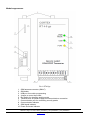
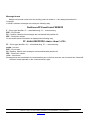
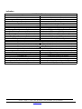
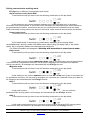
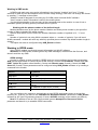
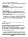
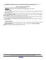
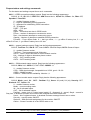
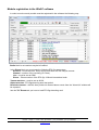
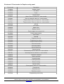
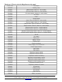
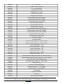
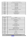
RT4-5gc object module V.3.0 User manual 2013 1 ©Korteks Liksnas 7, Riga, LV-1003, Latvia, phone/fax: (+371)-67505604, (+371)-67505603 E-mail: [email protected], http://www.cortex.lv Table of contents General information............................................................................................................. 3 Device preferences............................................................................................................. 3 Technical information.......................................................................................................... 3 Module appearance............................................................................................................. 4 User configuration............................................................................................................... 5 Device inputs and outputs...................................................................................................5 First start and general programming....................................................................................5 Message format................................................................................................................... 6 Indication............................................................................................................................. 7 Setting communicator working mode...................................................................................8 Working in SMS mode.........................................................................................................9 Working in GPRS mode......................................................................................................9 Working in Control panel mode.........................................................................................10 Device programming................................................................................................................... 11 Module zone configuration.......................................................................................................... 12 Dallas mode................................................................................................................................ 13 Key-switch mode......................................................................................................................... 14 Remote arming and disarming....................................................................................................15 Request status and settings commands............................................................................16 Module registration in the WinSC software........................................................................17 Connecting external devices.............................................................................................18 Enclosure 1. Terminal block pins.......................................................................................22 Enclosure 2. Module control commands............................................................................22 Enclosure 3. Module service commands..........................................................................23 Enclosure 4. Module events..............................................................................................25 Note! Module events are transmitted with partition 99......................................................25 Enclosure 5. Event codes for Esprit security panel............................................................26 Enclosure 6. Event codes for Magellan security panel .....................................................27 Enclosure 7: Key-BUS event codes...................................................................................29 2 ©Korteks Liksnas 7, Riga, LV-1003, Latvia, phone/fax: (+371)-67505604, (+371)-67505603 E-mail: [email protected], http://www.cortex.lv General information RT4-5gc object device is designed for collecting information from control panel, it's processing and transmitting it to the Central Unit and/or 3 registered mobile phones. Device has 5 general purpose inputs, power supply control input, 2 outputs that can be used either as PGM or as manually activated outputs and communication port that is used for connecting various security panels. Since version 3.0 RT4-5gc has 7* switchable working modes: 1 – working with Serial BUS (same as RT4-5se v.2.0), 2 – control panel mode, 3 - working with Esprit control panels, 4 - working with Magellan control panels, 5 - working with one- or two-partitioned DSC control panels, using Key-BUS protocol, 5 working with multipartitioned (more than two partitions) DSC control panels, using Key-BUS protocol, 7 working with Digiplex control panels. * Number of working modes may be enhanced in the future. Device preferences - Ability to transmit information via SMS and GPRS; 63 event log; USB port for module settings programming; GSM-modem state, signal strengths and data transmitting indication; 5 general purpose inputs; power supply control input; 2 manually activated/PGM outputs; Communication port for connecting to various security pannels; Ability to work in control panel mode; Supports up to 3 users + installer; Two switchable message modes: "User" and "Modem"; Periodic channel test; Technical information GSM-protocol GSM-modem SIM interface Number of users Output capacity Maximum voltage on closed output Maximum voltage on closed inputs Supply voltage Input current (at 12V supply) Input current in GPRS mode Overall dimensions, mm 3 E-GSM 900/1800/GPRS Quectel M12 3 and 1,8 V 3 + installer 1A 30V 30V 11 – 30V 15mA 150mA 160х70х25 ©Korteks Liksnas 7, Riga, LV-1003, Latvia, phone/fax: (+371)-67505604, (+371)-67505603 E-mail: [email protected], http://www.cortex.lv Module appearance Pic.1. RT4-5gc 1. GSM antenna connector (SMA-F) 2. SIM holder 3. USB-port for module programming 4. Jumper to control input load 5. Dip-Switch for changing working mode 6. Terminal block for power supply and external device connection 7. Communication port for connecting security panels 8. Communication indicator 9. GSM signal indicator 10. Power and mode indicator 4 ©Korteks Liksnas 7, Riga, LV-1003, Latvia, phone/fax: (+371)-67505604, (+371)-67505603 E-mail: [email protected], http://www.cortex.lv User configuration You can program four phone numbers into the device. The first three numbers are user numbers, and the fourth is the installer’s number. Installer doesn’t receive any SMS-messages (excluding replies on some commands) and has full rights to control and program the module. Installer’s rights are hardcoded and cannot be changed. In order for module to function correctly numbers of the first user and installer must be programmed. Other two numbers can be added if needed. First users and installer’s numbers can be the same. Device inputs and outputs. Device inputs can be loaded to «0» or to «+». Choice is made using the jumper. If jumper is removed, inputs are loaded to «+» (reacts to «0»/«break» signals), if set – loaded to «0» (reacts to «+»/«break» signals). Maximum voltage on the input - +30V. By default all general purpose inputs (IN1-5) are programmed as NO and power supply control input (I6) as NC. Attention! When jumper is set all the inputs change their status to opposite. If you need to change input type, you have to connect all external devices, make sure they are in the normal state and send the following command to the module: 00.хххх where хххх – module security code. After receiving this command, module will set all input state as normal. Device outputs can work either as manually activated outputs or PGM outputs. Manually activated output is activated and deactivated using SMS-message. You can also activate it on time. PGM-output can react to the following troubles: GSM-signal lost, cannot connect to server or cannot establish GPRS connection. Outputs are configured using USB_Reader software. By default – manually activated. First start and general programming. Make sure that no phone numbers are saved in the SIM memory and the SIM card is activated. If PIN request is activated, make sure it is set as „0000”. After that you can insert the SIM into module. After that you can start module programming. Module is programmed using USB_Reader software. To turn on programming mode, just connect the USB cable and power the module. When POWER/MODE indicator will turn red you can start programming. First you must program installer’s and the first user’s numbers, module account and, if you are going to use module in GPRS mode, server IP-address, TCP-port, APN and module Online ID. In order for the module to work correctly with TLF_Server and WinSC software, OnlineID must be set the same as the module telephone number (without international code). In case if it is not possible to use USB_Reader software, you can program the module using SMS messages. To do so, power the module and, after successful initialization (green ST indicator is on), send to the module the following message: 94.хх...хх where хх...хх – installer’s phone number (if the phone is registered with the international code, you must use + before it). After that, installer will receive “Reply SECURITY CODE” message. Installer must reply to that message with the module security code (default – 1234). It must be done within 10 minutes after receiving the message. Otherwise phone number will be deleted from the device memory and you will have to start all over. If the number is successfully programmed, installer will receive „OK” message. Note! If the installer’s phone is not programmed, module will ignore all SMS-messages except for 94.хх...хх. After programming installer’s number, you have to program first user’s (Central Unit) number. To do so, send from installer’s phone the following message 91.хх...хх where хх...хх – first user’s phone number (if the phone is registered with the international code, you must use + before it). Then you have to change device account. To do so, send from installer’s phone the following message 95.xxxxyyyy where xxxx – module security code (default – 1234) and yyyy – new account. After that you can program the module to connect to the TLF_Server software. Full command list is set in the “Working in GPRS mode” paragraph. 5 ©Korteks Liksnas 7, Riga, LV-1003, Latvia, phone/fax: (+371)-67505604, (+371)-67505603 E-mail: [email protected], http://www.cortex.lv Message format Module events and events from the security panels in modes 3 - 6 are always transmitted in ContactID. In WinSC software messages are looking the following way: Partitions=PP EventCode=FEEEZZZ F – Event type identifier: E — alarm/disarming, R — restore/arming. EEE – Event code. PP – Partition. Module own messages are transmitted with partition 99. ZZZ – Zone/User number. On the mobile phone information is displayed the following way: FF, AAAA,EEEPPZZZ:<date>-<time>*<CS> FF – Event type identifier: 06 — alarm/disarming, 07 — restore/arming. AAAA - Account EEE – Event code. PP –Partition. Module own messages are transmitted with partition 99. ZZZ – Zone/User number. <CS> - Check sum. Messages that are transmitted via communication port in the first mode are not converted into ContactID and their format depends on the connected device type. 6 ©Korteks Liksnas 7, Riga, LV-1003, Latvia, phone/fax: (+371)-67505604, (+371)-67505603 E-mail: [email protected], http://www.cortex.lv Indication POWER/MODE indicator Off Green Blinks green fast Flashes green once per second Red Flashes red Module not ready to work Module is ready to work Message is transmitted Low voltage Module in programming mode SIM-card is not registered in the module GSM indicator Green. Flashing once every 2-3 seconds Module in GPRS mode. GSM signal at high level Orange. Flashing once every 2-3 seconds Module in GPRS mode. GSM signal at medium level Red. Flashing once every 2-3 seconds Module in GPRS mode. GSM signal at low level Flashing green once every 2-3 seconds Module in SMS mode. GSM signal at high level Flashing orange once every 2-3 seconds Module in SMS mode. GSM signal at medium level Flashing red once every 2-3 seconds Module in SMS mode. GSM signal at low level Flashing red once per second Out of GSM coverage PORT indicator Indication in Serial BUS mode Flashes yellow Transmitting information via communication port Indication in Esprit and Magellan modes Flashes yellow Transmitting information via communication port Indication in DSC 1 and DSC 2 modes Flashes yellow Transmitting information via communication port Blinks yellow fast for 2 seconds Wrong working mode is selected Key reader or key switch LED Constantly on Disarmed. Ready to be armed Off Disarmed. Not ready to be armed Double flashing once every 2 seconds Armed Flashes constantly User key programming mode ON Triple flashing once every 2 seconds Guard key programming mode ON 7 ©Korteks Liksnas 7, Riga, LV-1003, Latvia, phone/fax: (+371)-67505604, (+371)-67505603 E-mail: [email protected], http://www.cortex.lv Setting communicator working mode RT4-5gc has six different communication port modes: Serial interface mode (Serial BUS). To activate this mode you have to set the following combination on the dip-switch: In this mode you can connect interface modules to the communication port, for acquiring information from control panels. In this mode all the messages are transmitted in the same format they are generated by the device, connected to the port (no conversion into ContactID format are made). When connecting security panel to the device in this mode, make sure that their accounts are identical. Control panel mode To activate this mode you have to set the following combination on the dip-switch: In this mode device is monitoring it's inputs status, depending on the arming status (armed/disarmed). Arming is made using Dallas touch memory keys, proximity chips or key-switch option. Key or proximity readers are connected to the serial port. For further information see paragraph «Working with transmitter in control panel mode». Esprit mode To activate this mode you have to set the following combination on the dip-switch: In this mode you can connect PARADOX ESPRIT 7x8 (V 3.00 and higher) security panel. Panel is connected via it’s specialized serial port. All the panel’s messages are converted into ContactID format (see table 6). All messages are transmitted with the RT4-5gc account. Magellan mode To activate this mode you have to set the following combination on the dip-switch: In this mode you can connect PARADOX panels of the E, SP and MG series. Panel is connected via it’s specialized serial port. All the panel’s messages are converted into ContactID format (see table 6). All messages are transmitted with the RT4-5gc account. DCS 1 To activate this mode you have to set the following combination on the dip-switch: In this mode communication port is connected to the Key-BUS line of the one- and twopartitioned DSC security panels. All messages are transmitted with the RT4-5gc account. DSC 2 To activate this mode you have to set the following combination on the dip-switch: In this mode communication port is connected to the Key-BUS line of the DSC security panels that has more than two partitions. All messages are transmitted with the RT4-5gc account. 8 ©Korteks Liksnas 7, Riga, LV-1003, Latvia, phone/fax: (+371)-67505604, (+371)-67505603 E-mail: [email protected], http://www.cortex.lv Working in SMS mode. In SMS mode each user can receive information in two formats: "modem" and "user". Format selection is made by user and depends on the module usage strategy. Each user can change the format by sending "*" message to the module. "Modem" format is designed for receiving by CU-GSM central unit and WinSC software. "User" format is used if information is send to the mobile phone. You should pay attention to the accuracy of the commands sent to the module. In case of lost or redundant symbol (including spaces) command will be ignored. Working with the phone numbers of the defined length. Module identifies users by the phone number. Module can define phone number by the specified number of digits, instead of the whole number. Symbol count starts from the end of the number. Maximum number of symbols is 16, "+" is not counted. Number of symbols is set using 99.Nx command, where х – number of symbols. If you will send 99.N0 command – module will work only with fully specified phone numbers. By default number length is set as 8. This option can also be configured using USB_Reader software. Working in GPRS mode. Using GPRS, module can directly transmit information into WinSC software. Attention! In GPRS mode, module ignores any SMS messages, received from the first user, and doesn't send him any SMS. GPRS-settings In order for module to work correctly in GPRS mode you must configure the following parameters: APN (Access point name to connect to the GPRS service), Central Unit IP-address, Central Unit TCP PORT, Online ID (module online identifier), Central unit Domain name (if used), Central Unit DNS Server IP (if used). These parameters can be configured using USB_Reader software or by sending a command to the module: 99.I<IP> 99.A <access point> 99.P<port> 99.R<attempts> 99.W<ID> 99.M<min> 99.DI<IP> 99.DD<domain name> IP-address APN TCP-port Number of attempts to connect to server Online identifier Time between attempts to connect to server IP-address of DNS server (if used) Domain name (if used) You can configure the module to automatically go into GPRS mode and connect to server after powering on. To do so, you have to set “Attempts For Reconnect Online” parameter in USB_Reader software as 255 (see Programming manual) or send a 99.R255 message to the module (see table 4). Note! If IP-address is set as 0.0.0.0 than module ignores Attempts For Reconnect Online parameter and doens't try to establish GPRS connection. 9 ©Korteks Liksnas 7, Riga, LV-1003, Latvia, phone/fax: (+371)-67505604, (+371)-67505603 E-mail: [email protected], http://www.cortex.lv Forced exit from GPRS mode For power saving purposes module can exit GPRS mode if there are troubles with power supply. You can specify conditions on which module will exit GPRS. Those can be specified either by USB_Reader software, or by the following SMS commands: 99.F0 – Don't exit GPRS unless command 86.<security code> is received 99.F1 – Exit GPRS if power low. 99.F2 – Exit GPRS if 220V lost. 99.F3 – Exit GPRS if power low or 220V lost. If this option is enabled and the battery is low and/or power is lost (depends on the settings), the module will send E804000 (in ”modem” mode) or Check bat or power (in ”User” mode) message when an attempt to turn GPRS mode on is made. Mobile operator authorization for GPRS activation. In case if for GPRS activation you need to authorize with the mobile operator, you have to specify login and password. Those can be specified either by USB_Reader software, or by the following SMS commands: Login is set by the 99.Y1хххх command, where хххх – login. Password is set by the 99.Y2хххх command, where хххх – password. Number of symbols in login and password must not exceed 8. If you have to delete login or password send the following commands to the module: 99.Y1(delete login) and 99.Y2 (delete password). Online identifier In order to send a message to the module from the WinSC software, you have to assign a unique ID for it. In order for module to work correctly with the TLF_Server and WinSC software, ID would be the same as module phone number (without international code). Attention! ID must only contain digits and be maximum 15 symbols long. You can set online ID either by using USB_Reader software, or by sending 99.Wxxxx message, where хххх – identifier. By default online ID is set as 11111111. By sending 99.Wi command, you can set GSM-modem IMEI as module Online ID. Possible errors If failed to establish GPRS connection: GPRS error (in „User” mode) or E854001 (in „Modem” mode). Possible causes: wrong APN setting or unavailability of this service at the current mobile operator. If failed to connect to software or Central unit: Online error (in „User” mode) or E854002 (in „Modem” mode). Possible causes: wrong IP, TCP PORT settings. Firewall restrictions on the Central Unit. Working in Control panel mode In this mode device is monitoring it's inputs status, depending on the arming status (armed/disarmed). Arming is made using Dallas touch memory keys or key-switch option. Key reader or key-switch is connected to the serial port. In „Disarmed” mode any zone violation is monitored, but transmitted only violation of 24H zone and PWR zone. Other zone status is ignored. In ”Armed” mode any zone violation leads to device activation (depending on the input configuration and sequence of zone violation), siren activation and further message transmission to the Central Station. Zone restores are also transmitted to the Central Station 10 ©Korteks Liksnas 7, Riga, LV-1003, Latvia, phone/fax: (+371)-67505604, (+371)-67505603 E-mail: [email protected], http://www.cortex.lv Device programming Device programming is made using USB_Reader software via computer USB-port. To turn on programming mode, just connect the USB cable and power the module. When POWER/MODE indicator will turn red you can start programming. In order to program control panel parameters you have to open programming window through the main menu File/Read or by pressing icon and than select Panel mode tab. You can configure the following parameters: EntryDelay – entry delay EntryDelayForStay – entry delay for the STAY ARM mode Exit Delay – exit delay BellCutOff – siren working time when alarm is activated Z1 Type – type of the first zone. Three options available: 24h. Always activated and causes the alarm regardless of the system status (armed/disarmed) Interior. After the delayed zone has been activated, interior zone works same as delayed. If delayed zone wasn’t activated, it works as instant zone. Instant. Zone with this parameter has an exit delay, but will immediately activate the alarm when triggered after the exit delay is over. Z1 StayAway checkbox – first zone parameter that determines if zone will be ignored when system is armed in STAY ARM mode (Stay/Arm) or not (Normal). If zone type is 24h, than this parameter is ignored. Z3 Type – type of the third zone. Options are the same as for the first zone. Z3 StayAway checkbox – third zone parameter that determines if zone will be ignored when system is armed in STAY ARM mode (Stay/Arm) or not (Normal). If zone type is 24h, than this parameter is ignored. Z4 Type – type of the fourth zone. Options are the same as for the first zone. Z4 StayAway checkbox – fourth zone parameter that determines if zone will be ignored when system is armed in STAY ARM mode (Stay/Arm) or not (Normal). If zone type is 24h, than this parameter is ignored. Z5 Type - type of the fifth zone. Options are the same as for the first zone. Z5 StayAway checkbox – fifth zone parameter that determines if zone will be ignored when system is armed in STAY ARM mode (Stay/Arm) or not (Normal). If zone type is 24h, than this parameter is ignored. KeySwitch checkbox – determines whether arming will be made using electronic keys (deactivated), or key-switch (activated). PwrZone(Input6)RandomDelay checkbox – not used in current version. LinesWithSingleEOLResistor checkbox – determines type of the security loops. With EOL resistor (activated) or NC (deactivated). Settings are saved by pressing “OK” key. 11 ©Korteks Liksnas 7, Riga, LV-1003, Latvia, phone/fax: (+371)-67505604, (+371)-67505603 E-mail: [email protected], http://www.cortex.lv Module zone configuration Some module zones functions are strictly programmed and cannot be changed. Zone functions are following (see Pic.2): 1-st input: Programmable zone. 2-nd input: Entry/Exit. Delayed zone. Has entry and exit delays and usually is used for the front door. Entry and exit delays can be programmed for the duration you need. 3-rd input: Programmable zone. 4-th input: Programmable zone. 5-th input: Programmable zone. 6-th input: PWR. Input is designed for power supply monitoring and must be connected to the «ACF» output of the VSCS-1,5/VSC-3,0-12 devices or to the «OUT» output of the AC_detector device. 1-st output: Siren. In the control panel mode the first output is strictly programmed to work as a Bell PGM. Pic.2. 12 ©Korteks Liksnas 7, Riga, LV-1003, Latvia, phone/fax: (+371)-67505604, (+371)-67505603 E-mail: [email protected], http://www.cortex.lv Dallas mode In this mode arming and disarming is made using Dallas touch memory keys or proximity chips. Zone wiring in EOL mode Loop resistance in the normal state must be 6,8кΩ Arming Before arming close all secured doors and windows and stop moving within the sensor range. If at least one zone is triggered (opened) than object is not ready for arming and LED on the key reader won’t be lightened. System can be armed only if LED constantly lightened, i.e. all zones are in normal state and system is ready for arming. To arm the system you have to touch key reader with registered touch memory key. If you will touch the key reader while LED is turned off (not ready to arm), arming operation will be ignored and you will hear long sound signal. Additionally you will be shown the number of the violated zones by the LED blinking (number of blinks – number of the first violated zone). To arm the system, remove all causes that prevent arming and once again touch the key reader with the key. After the system is armed exit delay will be started. During this you can leave the secured space without triggering the alarm. Delay is indicated by sound signal that will beep once every two seconds and once a second during the last ten seconds of delay. After exit delay expires the system will be armed (LED will double-blink once every two seconds) and a message will be sent to the Central Station. If during exit delay you will touch the key reader with the registered key, the system will return to the disarm state without sending any message to the Central Station. Arming in STAY ARM mode To arm in STAY ARM mode at least one zone must have Stay/Away parameter enabled. If so, during the exit delay Entry/Exit zone (IN2) activation is monitored. If zone didn’t activate (door wasn’t open) STAY ARM mode is activated. In this mode, activation of the zone with enabled Stay/Away parameter is ignored. You can also set separate entry delay for this mode. If during the exit delay Entry/Exit zone was activated (door was opened) than arming is made in the standard mode. Disarming When entering secured space, delayed zone triggers. At that moment entry delay is started. Delay is indicated by constant sound signal. You have to disarm the system (touch the key reader with registered touch memory key) before delay hasn’t expired. In that case “Disarmed” message will be sent to the Central Station. Otherwise an alarm message will be sent. Touch memory/proximity key registration You can program three key types in the device: “Master”-key – the first key that was put to the key reader. Using this you can turn on key programming modes. 13 ©Korteks Liksnas 7, Riga, LV-1003, Latvia, phone/fax: (+371)-67505604, (+371)-67505603 E-mail: [email protected], http://www.cortex.lv User keys – keys that are used to arm and disarm the system. Guard keys – keys that are used to confirm that security crew arrived to the object after alarm receiving. You can’t arm or disarm the system or deactivate the siren using these keys. When this key is put to the key reader, transmitter forms and sends a special message to the Central Station. Registering the “Master”-key is made the following way: Touch the key reader with the “master”-key and wait for the triple beep. Registering the user keys is made the following way: Touch the key reader with the “master”-key (for approximately 1 second) – the device will turn on user key registration mode (indication LED blinks fast). Touch the key reader with the user keys, one after another. After touching the key reader with the key, you should either hear triple beep (if registration is successful) or one long beep (if the key is already registered). Maximum number of user keys is 16. To exit user key programming mode you have to wait 1 minute without touching the key reader (device will return to it’s normal mode) or touch the key reader with the “master”-key (device will switch to guard key registration mode). Registering the guard keys is made the following way: Touch the key reader with the “master”-key two times (for approximately 1 second each) – the device will turn on guard key registration mode (indication LED blinks three times once every 2 seconds). Touch the key reader with the guard keys, one after another. After touching the key reader with the key, you should either hear triple beep (if registration is successful) or one long beep (if the key is already registered). Maximum number of guard keys is 16. To exit user key programming mode you have to wait 1 minute without touching the key reader or touch the key reader with the “master”-key. To delete all registered keys, including the „master”-key you have to connect input 2 and the first contact on the interface port and power up the transmitter. To delete all registered user keys, you have to connect input 3 and the first contact on the interface port and power up the transmitter. To delete all registered guard keys you have to connect input 4 and the first contact on the interface port and power up the transmitter. Attention! When deleting master-key, module status is always changed to “Disarmed. Key-switch mode In this mode you can arm and disarm the system by connecting the 1-st and the 2-nd contacts on the interface port. Arming Before arming close all secured doors and windows and stop moving within the sensor range. If at least one zone is triggered (opened) than object is not ready for arming and LED on the key reader won’t be lightened. System can be armed only if LED constantly lightened, i.e. all zones are in normal state and system is ready for arming. To arm the system you have connect the 1-st and the 2-nd contacts on the interface port. If you will connect them while LED is turned off (not ready to arm), arming operation will be ignored and you will hear long sound signal. Additionally you will be shown the number of the violated zones by the LED blinking (number of blinks – number of the first violated zone). To arm the system, remove all causes that prevent arming, disconnect the contacts and then connect them again. After the system is armed exit delay will be started. During this you can leave the secured space without triggering the alarm. Delay is indicated by sound signal that will beep once every two seconds and once a second during the last ten seconds of delay. After exit delay expires the system will be armed (LED will double-blink once every two seconds) and a message will be sent to the Central Station. If during exit delay you will disconnect the contacts, the system will return to the disarm state without sending any message to the Central Station. Disarming When entering secured space, delayed zone triggers. At that moment entry delay is started. Delay is indicated by constant sound signal. You have to disarm the system (disconnect the contacts) before delay hasn’t expired. In that case “Disarmed” message will be sent to the Central Station. Otherwise an alarm message will be sent. ©Korteks 14 Liksnas 7, Riga, LV-1003, Latvia, phone/fax: (+371)-67505604, (+371)-67505603 E-mail: [email protected], http://www.cortex.lv Attention! To deactivate the siren that has activated during the disarmed state (24H zone) you have to connect and then disconnect the 1-st and the 2-nd contacts on the interface port. Remote arming and disarming Module can be armed and disarmed using SMS message. Attention! Valid remote arming and disarming is possible only in Dallas mode. Remote arming In order to remote arm the module you have to send it the following message 11.хххх where хххх — module security code. When message is received, module analyses all it’s input status and, depending on the result, performs one of the two actions: 1) If all zones are in the normal state than module changes it’s status to “armed” and Remote ARM (R840016 in “modem” mode) message is sent to the users. 2) If one or more zones are in the alarm state, than the module sends back the status message, where all of the alarmed zones are listed. Module stays in “Disarmed” state. This function is only available to the first three registered users. Installer doesn’t have the rights to send this message. Remote disarming In order to remote arm the module you have to send it the following message 12.хххх where хххх — module security code. When message is received, module changes it’s status to “Disarmed” and Remote DISARM (E840016 in “modem” mode) message is sent to the users. 15 ©Korteks Liksnas 7, Riga, LV-1003, Latvia, phone/fax: (+371)-67505604, (+371)-67505603 E-mail: [email protected], http://www.cortex.lv Request status and settings commands For the status and settings request there are 4 commands: 99.С1 —GPRS connection settings request. Reply has the following appearance: V:3210, L:, P:, IP:0.0.0.0, PORT:923, APN:internet.lmt.lv, QTime:30s, RTime: 3m, RAtt: 255, GprsAtt:2, ForceOff:1 V: - module firmware version. L: - login for establishing GPRS connection. P: - password for establishing GPRS connection. IP: - IP-address. PORT: - TCP port. APN: - APN. Qtime: - connection test time in GPRS mode. RTime: - number of attempts to reconnect to server. Ratt: - time between attempts to reconnect to server. GprsAtt: - Number of attempts to establish GPRS connection. ForceOff: - Force offline mode. 0 — don’t go offline, 1 — go offline if battery low, 2 — go offline if AC lost, 3 - go offline if battery low or AC lost. 99.С2 — general settings request. Reply has the following appearance: V:3210, TestTime:144, SIA IP: OFF, Lnr:8, OUT1: General Output, OUT2: General Output V: - module firmware version. TestTime: - Test message period*10minutes. SIA IP: - SIA IP mode. Not used in current module version. LNr: - Number of digits to determine phone number. OUT1: - OUT1 working mode. OUT2: - OUT2 working mode. 99.С3 — GSM network status request. Reply has the following appearance:: V:3210, CSQ: 24,0; COPS: 0,0,”LMT GSM”; CGREG: 1,1 V: - module firmware version. CSQ: - GSM signal strength. Acceptable level 15-20, good – 20–30. COPS: - Mobile operator. CGREG: - GPRS service availability. Must be 1,1. 99.С4 — Current module status request. Reply has the following appearance: V:3210, Mode: panel, IN: , OUT: , PanStat: D(1), Users: U1(code) U4 (txt), Security: OFF, SimLock: OFF, Online: ON V: - module firmware version. Mode: - current working mode. IN: - list of activated inputs. OUT: - list of activated outputs. PanStat: - status (only in Control panel mode). D - disarmed, A - armed, StayA – armed in Stay Arm. In brackets is shown user number that changed the module status last. Users: - list of registered users. In brackets is shown message format: text or codes. Security: - security mode. ON/OFF. SimLock: - SIM-card strict assignment for the module. ON/OFF Online: - Shows if module is in the GPRS node or not. 16 ©Korteks Liksnas 7, Riga, LV-1003, Latvia, phone/fax: (+371)-67505604, (+371)-67505603 E-mail: [email protected], http://www.cortex.lv Module registration in the WinSC software In order to work correctly module must be registered in the software the following way: Radio block is not used an may be left unfilled. In the Phone block you must enter the following RT4-5gc parameters. Account – Device account. Every device must have it’s own unique account. Channel – number of the receiving (IP Client). Line – must be set as GSM Phone – Phone number of the RT4-5gc. Without international code. Transm.test time – must be set as 00:00. Object test time –RT4-5gp/security panel test period Reminder timeout – with this time period not restored alarm events from the “Alarm list” window will be repeated. Into the TLF Events tab you have to load RT4-5gs decoding card. 17 ©Korteks Liksnas 7, Riga, LV-1003, Latvia, phone/fax: (+371)-67505604, (+371)-67505603 E-mail: [email protected], http://www.cortex.lv Connecting external devices Connecting interface modules with Serial BUS support (1-st mode) Connecting security panel of the MAS800 system(1-st mode) Connecting the key reader in control panel mode (2-nd mode) Attention! Depending on reader model, wire colors may vary Connecting proximity reader in control panel mode (2-nd mode) 18 ©Korteks Liksnas 7, Riga, LV-1003, Latvia, phone/fax: (+371)-67505604, (+371)-67505603 E-mail: [email protected], http://www.cortex.lv Connecting Esprit and Magellan control panels (3-rd and 4-th modes) Connecting to the Key-BUS of the DSC control panel (6-th and 7-th modes) Zone wiring in EOL loop mode 19 ©Korteks Liksnas 7, Riga, LV-1003, Latvia, phone/fax: (+371)-67505604, (+371)-67505603 E-mail: [email protected], http://www.cortex.lv Connecting external devices in control panel mode (2-nd mode) Attention! Piezoelectric beeper must be connected to the reader. 20 ©Korteks Liksnas 7, Riga, LV-1003, Latvia, phone/fax: (+371)-67505604, (+371)-67505603 E-mail: [email protected], http://www.cortex.lv Connecting external devices in control panel mode (2-nd mode) Attention! Piezoelectric beeper must be connected to the reader. 21 ©Korteks Liksnas 7, Riga, LV-1003, Latvia, phone/fax: (+371)-67505604, (+371)-67505603 E-mail: [email protected], http://www.cortex.lv Enclosure 1. Terminal block pins Table 1. Pin Name I/O Description 1 12V- I 2 12V+ I 3 ┴ 4 IN1 I Alarm input 1 5 IN2 I Alarm input 2 6 IN3 I Alarm input 3 7 IN4 I Alarm input 4 8 IN5 I Alarm input 5 9 ACF I AC lost input 10 OUT1 О Output 1 11 OUT2 О Output 2 Module power supply Ground Enclosure 2. Module control commands. Table 2. Command * Description Change message format Reply /Status/1 By default allowed to: Everyone 0 Request status /Status/ Everyone 1 Activate Out 1 E802001 U1, U2, U42 2 1.ххх 3 Deactivate Out 1 Activate Out 1 on time (ххх – minutes) Activate Out 2 R802001 E802001 E802002 U1, U2, U4 U1, U2, U4 U1, U2, U4 4 3.xxx Deactivate Out 2 Activate Out 2 on time (ххх – minutes) Restart module (хххх – security code) Restart GPRS mode to apply new settings (only in GPRS mode) R802002 E802002 U1, U2, U4 U1, U2, U4 R308000 U1, U4 --- Server 081.хххх 85 11.хххх Remote arming (in control panel mode) Depending on the result3 U1 12.xxxx Remote disarming (in control panel mode) E840016 U1 Notes: 1) Status is a list of all active modes and alarms. 2) U1, U2, U3, U4 – User numbers; U1 – Master, U4 - Installer 2) See paragraph «Remote arming and disarming». 22 ©Korteks Liksnas 7, Riga, LV-1003, Latvia, phone/fax: (+371)-67505604, (+371)-67505603 E-mail: [email protected], http://www.cortex.lv Enclosure 3. Module service commands. Table 3. Command Description Reply By default allowed to: 00.хххх Set current state as normal (хххх – module security code) /Status/ U1, U4 U1, U4 81 Request master phone number /TLF number/ 82 Request 2-nd user phone number /TLF number/ 83 Request 3-rd phone number /TLF number/ 84 Request installer’s phone number /TLF number/ 92 Delete 2-nd user phone number E801000 U1, U4 93 Delete 3-rd phone number E801000 U1, U4 94 Delete installer’s phone number E801000 U1, U4 91.xx...xx1 Change master phone number E801000 U1, U4 92.xx…xx 93.xx…xx Change 2-nd user phone number Change 3-rd phone number E801000 E801000 U1; U2 U1; U3 94.xx…xx Change installer’s phone number2 E801000 U1; U4 E803000 U1, U4 E803000 U1, U4 95.xxxxyyyy 96.xxxxyyyy 87.xxxx 99.CddMMyyhhmms s3 99.Wxxxx 99.Тххх 99.I<IP> 99.DI<IP> 99.DD<domain name> 99.A<access point> 99.P<port> 23 Change module account хххх – security code, уууу – new account Change security code хххх – old code, уууу – new code Turn on GPRS-mode (xxxx - module security code) Set time and date (dd – day, MM – month, yy – year, hh – hours, mm – minutes, ss seconds) Set module online ID. хххх – identifier (15 digits max.) Set test period (ххх – time *10 minutes. Max. - 255) Depending on the result4 U1, U4 U1, U4 E801000 U1, U4 E801000 U1, U4 E801000 U1, U4 Set server IP-address E801000 U1, U4 Set DNS-server IP-address (if used) E801000 U1, U4 Set domain name (if used)4 E801000 U1, U4 Set APN E801000 U1, U4 Set TCP-port E801000 U1, U4 ©Korteks Liksnas 7, Riga, LV-1003, Latvia, phone/fax: (+371)-67505604, (+371)-67505603 E-mail: [email protected], http://www.cortex.lv Command Description Reply By default allowed to: 99.R<attempts> Number of attempts to connect to server. Max. - 255 E801000 U1, U4 99.O<sec> GPRS channel test period Min - 15. Max - 255 E801000 U1, U4 99.M<min> Time between attempts to reconnect to server Max - 255 E801000 U1, U4 Set login for GPRS service Max – 8 symbols E801000 U1, U4 Set password for GPRS service Max – 8 symbols E801000 U1, U4 99.Nx Set number of symbols for number recognition. Max - 16 E801000 U1, U4 99.С1 Show module online configuration /Configuration/ U1, U4 99.С2 Show module general configuration /Configuration/ U1, U4 99.С3 Show operator and GSM-signal strength5 /Configuration/ U1, U4 99.C4 Show user configuration, current working mode, input and output status and configuration /Configuration/ U1, U4 99.Y1<login> 99.Y2<password> Notes: 1. Phone numbers can be registered either with international code or without it. Inf international code is used than it must contain «+» before it (for example, Latvia: +371ххххххх, Estonia: +372ххххххх, Russia: +7хххххххххх). Maximum phone length – 15 digits. 2. When changing installer, new installer will receive Reply SECURITY CODE message. New installer must reply with a security code within 10 minutes. Otherwise old phone number will remain registered. 3. Date and time are added to every message. To receive the correct time you either have to activate GPRS mode or send this SMS-message. Attention! After restarting module time and date will be lost and you will have to set them again. 4. See paragraph «Working in GPRS mode». 5. If you need to stop using domain name and start using IP-address again, just delete DNS-server IP-address. You can do so by sending 99.DI message. 6. Normal signal strength - 15-20 points, good – 20-30. 24 ©Korteks Liksnas 7, Riga, LV-1003, Latvia, phone/fax: (+371)-67505604, (+371)-67505603 E-mail: [email protected], http://www.cortex.lv Enclosure 4. Module events. Event code in SMS-message on mobile WinSC software phone (by default) E802001 OUT 1 activated E802002 OUT 2 activated R802001 OUT 1 deactivated R802002 OUT 2 deactivated E803000 Code changed E830001 Alarm zone 1 E830002 Alarm zone 2 E830003 Alarm zone 3 E830004 Alarm zone 4 E830005 Alarm zone 5 E830006 AC lost E822000 Battery low E804000 Check bat or power E801000 Configuration changed E854001 GPRS error E854002 Online error R830001 Restore zone 1 R830002 Restore zone 2 R830003 Restore zone 3 R830004 Restore zone 4 R830005 Restore zone 5 R830006 AC restored R822000 Battery restored E823000 Test R808000 Ready E829000 Key program mode ON R829000 Key program mode OFF R8400xx Armed by user xx E8400xx Disarmed by user xx R840016 Remote ARM E840016 Remote DISARM R8410xx Stay Armed. User xx E8410xx Stay Disarmed. User xx E8580xx Guard key xx E833020 Port failure R833020 Port OK Description By default sent to: Out 1 activated Out 2 activated Out 1 deactivated Out 2 deactivated Account/Security code changed Alarm zone 1 Alarm zone 2 Alarm zone 3 Alarm zone 4 Alarm zone 5 AC lost Battery low Forced exit from GPRS mode Module configuration changed Error establishing GPRS connection Error connecting to server Restore zone 1 Restore zone 2 Restore zone 3 Restore zone 4 Restore zone 5 AC restored Battery restored Test message Module is ready to work Key registration mode entry Key registration mode exit Armed by user хх Disarmed by user xx Module is remotely armed Module is remotely disarmed User хх armed module in Stay Arm mode User хх disarmed module in Stay Arm mode Guard xx touched the reader with his key Communication port failure Communication port restored Command sender Command sender Command sender Command sender Command sender U1, U2 U1, U2 U1, U2 U1, U2 U1, U2 U1 U1 U1 Command sender Note! Module events are transmitted with partition 99 25 ©Korteks Liksnas 7, Riga, LV-1003, Latvia, phone/fax: (+371)-67505604, (+371)-67505603 E-mail: [email protected], http://www.cortex.lv U1 U1 U1, U2 U1, U2 U1, U2 U1, U2 U1, U2 U1 U1 U1 U1 U1 U1 U1 U1 U1 U1 U1 U1 U1 U1 U1 Enclosure 5. Event codes for Esprit security panel Event code Description E100000 Auxiliary alarm E115000 Fire alarm E120000 Panic E121000 Duress alarm E1300xx Alarm! Zone xx, where xx - zone number R1300хх Zone хх restored, where xx - zone number E1370хх Tamper alarm! Zone хх, where xx - zone number R1370хх Tamper restore. Zone хх, where xx - zone number E301000 AC fail R301000 AC restore E302000 Battery low R302000 Battery restore E312000 Power supply over current limit R312000 Power supply restore E321000 Bell trouble R321000 Bell OK E351000 Telephone line fail R351000 Telephone line restore R354000 Communication restore E373000 Fire zone trouble R373000 Fire zone restore E401000 Special disarming R401000 Special arming E4010хх Disarmed by user хх, where xx - user number R4010хх Armed by user хх, where xx - user number E405000 Auto-arm canceled E406000 Alarm canceled E421000 Keypad lockout E452000 Late open/close E459000 Recent closing E456000 Partial arming E5700хх Zone bypass, where xx - zone number E602000 Periodic test E626000 Date/time loss E625000 Date/time restore E627000 Programming mode entry 26 ©Korteks Liksnas 7, Riga, LV-1003, Latvia, phone/fax: (+371)-67505604, (+371)-67505603 E-mail: [email protected], http://www.cortex.lv Enclosure 6. Event codes for Magellan security panel Event code Description E100000 Auxiliary alarm E1000xx Medical alarm, where xx - user number E1100хх Fire zone alarm, where xx - zone number R1100хх Fire zone restore, where xx - zone number E115000 Fire alarm E120000 Panic E121000 Duress alarm E1300xx Alarm! Zone xx, where xx - zone number R1300хх Zone хх restore, where xx - zone number E1370хх Tamper alarm. Zone хх, where xx - zone number R1370хх Tamper restore. Zone хх, where xx - zone number E1430хх Module trouble, where xx - module address R1430хх Module restore, where xx - module address E1450хх Wireless module tamper alarm, where xx - module address R1450хх Wireless module tamper restore, where xx - module address E301000 AC fail R301000 AC restore E302000 Battery low R302000 Battery restore E305000 System reset E308000 System shutdown E312000 Power supply over current limit R312000 Power supply restore E321000 Bell trouble R321000 Bell restore E333000 Expansion module trouble R333000 Expansion module restore E338000 Expansion module low battery R338000 Expansion module battery restore E341000 Expansion module tamper alarm R341000 Expansion module tamper restore E342000 Expansion module AC lost R342000 Expansion module AC restore E344001 RF jamming E344002 GSM jamming R344001 RF restored R344002 GSM restored E350000 GSM – no service 27 ©Korteks Liksnas 7, Riga, LV-1003, Latvia, phone/fax: (+371)-67505604, (+371)-67505603 E-mail: [email protected], http://www.cortex.lv E350001 IP – no service R350000 GSM - service restored R350001 IP - service restored E351000 Telephone line 1 fail R351000 Telephone line 1 restore E352000 Telephone line 2 fail R352000 Telephone line 2 restore E354001 Communication fault (voice report) E354002 Communication fault IP1 (GPRS) E354003 Communication fault IP2 (GPRS) E354004 Communication fault IP1 E354005 Communication fault IP2 R354000 Communication restored R354001 Communication restored (voice report) R354002 Communication restored IP1 (GPRS) R354003 Communication restored IP2 (GPRS) R354004 Communication restored IP1 R354005 Communication restored IP2 E373000 Fire zone trouble R373000 Fire zone restore E3800xx Sensor trouble, where xx - sensor number R3800xx Sensor restore, where xx - sensor number E381000 Loss of supervision — RF E381001 Loss of supervision — GSM E381002 Loss of supervision — IP R381000 Supervision restore — RF R381001 Supervision restore - GSM R381002 Supervision restore – IP E3840хх Wireless sensor battery low, where xx - sensor number R3840хх Wireless sensor battery restore, where xx - sensor number E400000 Open after alarm (Winload/keyswitch) E4000хх Open after alarm, where xx - user number R400000 Special closing E401000 Disarmed (Winload/keyswitch) E4010хх Disarmed, where xx - user number R4010хх Armed, where xx - user number R403000 Auto-arming E405000 Auto-arm canceled R408000 Quick arm R409000 Arming using Keyswitch 28 ©Korteks Liksnas 7, Riga, LV-1003, Latvia, phone/fax: (+371)-67505604, (+371)-67505603 E-mail: [email protected], http://www.cortex.lv E406000 Alarm canceled (Winload/keyswitch) R4060хх Alarm canceled by user, where xx - user number E421000 Keypad lockout E452000 Late open/close E456000 Partial arming E4580хх Disarmed using StayD, where xx - zone number E459000 Recent closing E531000 Module added E532000 Module deleted E5700хх Zone bypass, where xx - zone number E602000 Periodic test E625000 Date/time restore E626000 Date/time lost E627000 Programming mode entry E628000 Programming mode exit E654000 System inactivity Enclosure 7: Key-BUS event codes Event code Description E1300xx Alarm! Zone xx, where xx - zone number R1300хх Zone хх restored, where xx - zone number E100000 Auxiliary alarm R100000 Auxiliary alarm restored E115000 Fire alarm R115000 Fire alarm restored E120000 Panic R120000 Panic restored E111000 2-wire smoke detector alarm R111000 2-wire smoke detector restore E121000 Duress alarm E139000 Intrusion verify E143000 Expansion module trouble R143000 Expansion module restore E1450хх Expansion module tamper alarm, where хх — module address R1450хх Expansion module tamper restore, where хх — module address E301000 AC lost R301000 AC restore E302000 Battery low R302000 Battery restore 29 ©Korteks Liksnas 7, Riga, LV-1003, Latvia, phone/fax: (+371)-67505604, (+371)-67505603 E-mail: [email protected], http://www.cortex.lv R305000 System reset (Cold start) E321000 Bell trouble R321000 Bell restore E3330хх Module fail, where xx - module address R3330хх Module restore, where xx - module address E351000 Telephone line fail R351000 Telephone line restore R354000 Communication restore E373000 Fire zone trouble R373000 Fire zone restore E3830хх Zone хх tamper alarm, where xx - zone number R3830хх Zone хх tamper restore, where xx - zone number E384000 Wireless key battery low R384000 Wireless key battery restore E3840хх Wireless sensor battery low, where xx - sensor number R3840хх Wireless sensor battery restore, where xx - sensor number E400000 Special opening R400000 Special closing E4010хх Disarmed by user хх, where xx - user number R4010хх Armed by user хх, where xx - user number E402040 Disarmed with master code R402040 Armed with master code E405000 Auto-arm canceled E406000 Open after alarm E421000 Keypad lockout E459000 Recent closing E470000 Partial arming E601000 System test E602000 Periodic test E627000 Programming mode entry E628000 Programming mode exit 30 ©Korteks Liksnas 7, Riga, LV-1003, Latvia, phone/fax: (+371)-67505604, (+371)-67505603 E-mail: [email protected], http://www.cortex.lv