1
Radio communication and control is supported through
the USB port. An on-board single chip; FTDI FT232R,
provides a USB to asynchronous serial data and control
interface to the radio. The entire USB bus protocol is
handled on the chip.
FTDI’s royalty-free Virtual Com Port (VCP) and D2XX
drivers eliminate the requirement for USB driver
development.
Virtual COM port (VCP) drivers cause the USB device to
appear as an additional COM port available to the PC.
Application software can access the USB device in the
same way as it would access a standard COM port.
D2XX drivers allow direct access to the USB device
through a DLL. Application software can access the USB
device through a series of DLL function calls. The
functions available are listed in the D2XX Programmer's
Guide.
The radio interface requires one cmos-level asynchronous serial port and two hardware flow
control bits. The additional two flow control bits are used to provide the maximum RF Data rates
between the radio and the USB interface, 250 kbs.
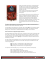
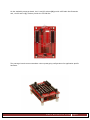
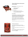
Two LED USB bus traffic indicators are provided; TXD and RXD (Ref. C). The indicators indicate
the communication status between the USB port and the FT232R. These indicators should be
blinking when communication is established between the USB port and the FT232R.
Radio Connection and Signal Strength Indicators
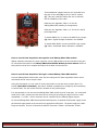
The LED associated status indicator (ASC, Green), indicates the radio’s status of association with
other radio’s on the network. When the radio is first powered-on, this LED will blink on-off at a
very low frequency, once connected to another radio, this indicator will stay on as long as the
association between radios remains (Ref. D). If the association is nulled, the LED will return to
the blinking on-off state.
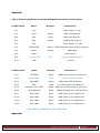
The radio interface has an additional feature; three LED radio signal strength indicators (Ref. E).
The LED radio signal strength indicators are three LED’s which provide an indication of the RF
received signal strength.
HSS (Green LED), is an abbreviation for High-Signal-Strength.
MSS (Yellow LED), is an abbreviation for Mid-Signal-Strength.
LSS (Red LED), is an abbreviation for Low-Signal-Strength.
An output from the radio (RSSI, pin 6), is converted to this visual three-level bargraph.
With
With
With
With
no signal, all LED’s will be off.
Low-Signal-Strength, the Red LED will be on.
Mid-Signal-Strength, the Red and Yellow LED’s will be on.
High-Signal-Strength, the Red, Yellow, and Green LED’s will be on.
©RnD Warehouse 2010 Page 2