1
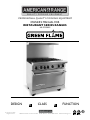
PROFESSIONAL QUALITY COOKING EQUIPMENT
OWNER’S MANUAL FOR
RESTAURANT SERIES RANGES
AR-GF SERIES
DESIGN
© 2012 American Range
All Rights Reserved
CLASS
FUNCTION
13592 Desmond St., Pacoima, CA 91331 818.897.0808 tel 888.753.9898 toll free www.americanrange.com
AR-GF Series Ranges
Owner’s Manual
Installation, Operation and
Maintenance Instructions
FOR YOUR SAFETY!
Do not store or use gasoline or
other flammable vapors or liquids
in the vicinity of this or any other appliance.
FOR
YOUR
SAFETY
WARNING
IMPROPER
INSTALLATION
WARNING!
Improper installation, adjustment, alteration, service
or maintenance can cause property damage, injury
or death and will void warranty. Read the
installation, operating and maintenance instructions
thoroughly before installing or servicing this equipment.
FOR
YOUR
SAFETY
WARNING
IMPROPER
INSTALLATION
IMPORTANT SERVICE NOTICE!
Using any part other than genuine American Range factory supplied
parts relieves the manufacturer of all liability.
American Range reserves the right to change specifications and
product design without notice. Such revisons do not entitle the buyer
to corresponding changes, improvements, additions or replacements
for the previously purchased equipment.
Instruction to be followed in the event the user smells gas should be posted
in a prominent location. This information should be obtained by
consulting the local gas supplier.
RETAIN THIS MANUAL FOR FUTURE REFERENCE.
This equipment is design engineered for commercial use only.
Model Number: __________________________________________
Serial Number: ___________________________________________
Purchase Date: ___________________________________________
Installed By: __________________________ Install Date:__________
Gas Type: _______________________________________________
Electrical Information: ______________________________________
13592 Desmond St., Pacoima, CA 91331 818.897.0808 tel 888.753.9898 toll free www.americanrange.com
PROFESSIONAL QUALITY COOKING EQUIPMENT
To Our Most Valued Customer:
Congratulations on your purchase of an American Range product. We hope you will enjoy the
design, manufactured quality, innovative features and cooking performance of this product – it
represents our continuing dedication to satisfying the most demanding needs of customers
like you.
Please read this manual and become familiar with important safety information about how
to install and set-up the unit, basic operating instructions, and how to maintain that just-likebrand-new appearance and performance - over years of day-to-day use.
If you should encounter any sort of problem, turn to the section of the manual entitled,
“Troubleshooting” – for a quick solution or guidance regarding the next step required to get
back to tip-top condition.
Thank you for choosing an American Range product for your kitchen. As you can expect,
this appliance is designed for years of reliable service. If you have any questions or comments,
please contact the dealer from whom you purchased the unit, or contact American Range
Customer Service via email: [email protected] at www.americanrange.com, or call
888.753.9898.
Sincerely,
Shane Demirjian
President, American Range Corporation
13592 Desmond St., Pacoima, CA 91331 818.897.0808 tel 888.753.9898 toll free www.americanrange.com
Owner’s Manual
AR-GF Series Ranges
Table of Contents
GENERAL................................................................................................................... 1
Important Safety Information...................................................................................... 1
Shipping Damage Claim Procedure......................................................................... 2
INSTALLATION.................................................................................................. 3-10
Installation, Operation & Service Personnel........................................................ 3
Ventillation Hoods............................................................................................................. 3
Gas Standards and Codes............................................................................................. 3
Manual Shut-Off Valve...................................................................................................... 4
Rating Plate............................................................................................................................. 4
Electric Standard & Codes............................................................................................ 5
Casters...................................................................................................................................... 6
Leveling..................................................................................................................................... 6
Electrical Connection........................................................................................................ 6
Gas Connection................................................................................................................... 7
Pressure Regulator............................................................................................................. 7
Gas Requirements.............................................................................................................. 7
Test Joints................................................................................................................................ 7
Couplings, Connectors, Casters................................................................................. 7
RANGE START UP PROCEDURE........................................................................ 8
TYPICAL MODELS AND PARTS IDENTIFICATION...................................... 9
INSTALLATION CHECKLIST..............................................................................10
Operating......................................................................................................11-12
Before Using Cook Top.................................................................................................11
Burner Operation.............................................................................................................11
Auto Re-ignition.................................................................................................................11
Radiant Broiler....................................................................................................................11
Grill...........................................................................................................................................12
Griddle....................................................................................................................................12
Hi-Shelf Installation...................................................................................13
Maintenance....................................................................................................14
Surface Broiler....................................................................................................................14
Griddle / Raised Griddle Broiler...............................................................................14
Oven........................................................................................................................................14
Summary................................................................................................................................14
Exploded View Drawing & PARTS LIST................................................15
CLEANING RECOMMENDATIONS.................................................................16
Troubleshooting..........................................................................................16
13592 Desmond St., Pacoima, CA 91331 818.897.0808 tel 888.753.9898 toll free www.americanrange.com
Owner’s Manual
AR-GF Series Ranges
WARNING
If the information in this manual is not followed exactly, a fire or
explosion may result causing damage, personal injury or death.
• INSTALLATION AND SERVICE MUST BE PERFORMED BY A
CERTIFIED / LICENSED INSTALLER, SERVICE AGENCY OR THE GAS SUPPLIER
• Do not store or use gasoline or other flammable vapors or liquids in the vicinity of this or any other appliance.
• WHAT TO DO IF YOU SMELL GAS
º Do not try to light any appliance.
º Do not touch any electrical switch, do not use any phone in your building.
º Immediately call your gas company. Follow the gas supplier instructions.
º If you cannot reach your gas supplier, call the Fire Department.
WARRANTY REQUIREMENT
For reliable operation and for your own safety, this professional cooking equipment
must be installed by a certified/licensed contractor.
Failure to comply will void any written or implied warranty.
Should the equipment require service during the standard warranty period, the
receipt proving certified installation must be made available to American Range for
verification.
If installation was not performed by a certified/licensed contractor be prepared to
submit a major credit card for payment for proper installation.
• Please observe all local and national codes and ordinances.
• Do not remove any permanent warning labels or plates from this product.
• Please ensure that this product is electrically grounded.
• Consumers should retain these instructions for local inspectors and for
future use.
• The included Anti-Tip Device must be installed prior to operation
1
13592 Desmond St., Pacoima, CA 91331 818.897.0808 tel 888.753.9898 toll free www.americanrange.com
Owner’s Manual
AR-GF Series Ranges
IMPORTANT - PLEASE READ AND FOLLOW!
•
•
•
•
•
•
Before beginning, please read all the instructions carefully.
DO NOT remove permanently affixed labels, warnings, or plates from product. This will void the warranty.
All local and national codes and ordinances must be observed; installation must conform with local codes.
The Installer must leave these instructions with the consumer who should retain for local inspector’s use and for future reference.
Installation and service must be performed by a qualified installer, service agency or gas supplier.
Please ensure that the product is properly grounded.
Your safety and the safety of others is very important. We have provided many important safety messages in this manual and on
your appliance. Always read and obey all safety messages.
!
!
!
!
This is the SAFETY ALERT SYMBOL.
This symbol alerts you to hazards.
DANGER
Hazards or unsafe practices which may result in severe
personal injury or death.
WARNING
Hazards or unsafe practices which may result in severe
personal injury or death.
CAUTION
Hazards or unsafe practices which may result in minor
personal injury or property damage.
Shipping Damage Claim Procedure
The equipment is crafted and inspected carefully by skilled personnel before leaving the factory. The transportation company
assumes full responsibility for the safe delivery upon acceptance of the equipment.
If you receive a damaged product, immediately contact your delivery company, your dealer, your builder or installer. Do not
install or attempt to operate a damaged appliance.
1. Note any visible loss or damage on the freight bill or express delivery and have the note signed by the person making
the delivery.
2. File claim for damages immediately regardless of the extent of damages.
3. For damage noticed after unpacking (concealed loss or damage), notify the transportation company immediately and file a “Concealed Damage” claim with them. This should be done within fifteen (15) days from the date that delivery is made to you. Retain the shipping container for inspection.
CALIFORNIA PROPOSITION 65 WARNING
The burning of gas cooking fuel generates some by-products which are on the list of substances known by the State of
California to cause cancer or reproductive harm. California law requires businesses to warn customers of potential exposure
to such substances. To minimize exposure to these substances, always operate this unit according to the Owners Manual,
ensuring you provide proper ventilation when cooking with gas.
2
13592 Desmond St., Pacoima, CA 91331 818.897.0808 tel 888.753.9898 toll free www.americanrange.com
Owner’s Manual
AR-GF Series Ranges
INSTALLATION
Installation, Operation and Service Personnel
Installation of the equipment should be performed by qualified, certified, licensed and/or authorized personnel who are experienced
in state/local installation codes.
Operation of the equipment should be performed by qualified or authorized personnel who have read this manual and understand
and are familiar with the functions of the equipment.
Service of the equipment should be performed by qualified personnel who are knowledgeable with American Range products.
VENTILATION HOODS
Means must be provided for any commercial, heavy-duty cooking appliance to exhaust combustion waste products to the outside
of the building. Usual practice is to place the unit under an exhaust hood. Filters and drip troughs should be part of any industrial
hood. Consult local codes before constructing and installing a hood.
Room air movement should be monitored during installation. Strong exhaust fans in the hood or in the overall air conditioning
system can produce a slight vacuum in the room and/or cause air drafts – either may interfere with the pilot or main burner
performance and can also be hard to diagnose. If pilot burner or main burner outage problems persist – make up air openings or
baffles may have to be provided in the room.
Installation - Gas Standards and Codes
Important - The installation of this appliance must conform to local codes or, in the absence of local codes, with the National Fuel
Gas Code ANSI Z223.1 Natural Gas Installation Code, CAN/CGA-B149-1 or the Propane Installation Code, CAN/CGA-B149-2
as applicable, including:
1. The appliance and its individual shut off valve must be disconnected from the gas supply piping system during any
pressure testing of that system at test pressure in excess of 1/2 psi (3.45 kPa).
2. The appliance must be isolated from the gas supply piping system by closing the individual manual shut-off
valve during any pressure testing of the gas supply piping system.
The appliance, when installed, must be wired and electrically grounded in accordance with local codes, or in the absence of local
codes, with the National Electric Code, ANSI/NFPA 70, or the Canadian Electrical Code, CSA C22.2 as applicable.
!
1.
2.
3.
DANGER
A manual gas shut-off valve must be installed in the gas supply (service) line ahead of the appliance and gas pressure
regulator in the gas stream for safety and ease of future maintenance/service.
The gas pressure regulator supplied with the appliance must be installed prior to connecting the equipment to the gas
supply line. Failure to install a regulator will void the equipment warranty and result in a potentially hazardous condition.
Please contact the factory, a factory representative, or local service company to perform maintenance and repairs.
3
13592 Desmond St., Pacoima, CA 91331 818.897.0808 tel 888.753.9898 toll free www.americanrange.com
Owner’s Manual
AR-GF Series Ranges
Gas Connection - The single deck oven requires one gas connection; the double deck oven requires two gas connections.
The gas inlet line size of this appliance is 3/4" NPT. For proper operation, the gas supply service line must be the same size or
greater than the inlet line size of the appliance.
Manual Shut-Off Valve - A gas pressure regulator and a contractor-supplied shut-off valve must be plumbed in the gas
service line ahead of the appliance – in a physical location where it can be reached quickly in the event of an emergency.
A
A
B
B
C
NATURAL GAS
A. Gas pressure regulator
B. 90º Street elbow
C. Adapter (must be 3/4" male pipe thread)
D. Flexible connector
E. Manual gas shut-off valve
F. 3/4" gas supply
G. Use pipe-joint compound
D
C
LP GAS
C
E
F
A. Gas pressure regulator
B. 90º Street elbow
C. Adapter (must be 3/4" I.O. male pipe thread)
D. Flexible connector
E. Manual gas shut-off valve
F. 3/4" gas supply
G. Use pipe-joint compound
H. Step down regulator
D
G
C
E
H
F
G
The gas pressure regulator must be installed in the gas line – failure to install a pressure regulator will void the equipment warranty. The
regulators supplied with ranges have 3/4" NPT connections; the regulator is adjusted at the factory for 5" W.C (water column) manifold
gas pressure (natural gas) or 10" W.C. manifold gas pressure for propane gas operation.
Before connecting the regulator, check the incoming line pressure – as these regulators can only withstand a maximum inlet pressure
of 14" W.C. (1/2 PSI); exceeding this pressure will damage them. Visually double check any installer-supplied intake pipes and/or blow
them out using compressed air to clear any dirt or debris, threading chips, or other foreign matter – before installing a service line.
Those particles will clog gas orifices when gas pressure is applied. Compounds used on threaded joints of this appliance piping must be
resistant to the action of NG and LP gas and provide a gas tight seal to prevent leaks. If the gas supply line pressure is greater than this
amount, a step-down regulator will be required. A gas flow direction arrow is cast into the body of the regulator to minimize installation
error – it should point downstream to the appliance. The blue air vent cap on the top of the regulator is part of the regulator and
should not be removed.
Any adjustment to the regulator must be
made only by qualified and licensed service
personnel with the proper calibrated test
equipment. Gas connections should be
performed by a qualified licensed contractor.
Intertek
Intertek
3013256
SERIAL NO. XXXXXX-XXX
MODEL: AR-GF-36
GAS TYPE: NAT
MAN. PRESS: 5.0
NOMINAL:
VAC 120
PHASE 1
INNOVECTION: VAC 120
CONVECTION: VAC 120
RATING PLATE - The information on the rating plate defines the model,
serial number, gas type (natural or liquid propane), operating pressures and burner
BTU ratings. Keep this information for future reference. It is essential for proper
identification of the unit when requesting additional information or factory support.
!
WARNING
IN. W.C.
ELECTRICAL RATINGS
AMP 15
PHASE 1
PHASE 1
AMP 3
AMP 5
HZ 60
HZ 60
HZ 60
INPUT-BTU/HOUR/BURNER
CLEARANCES
NON-COMB. COMB.
OPEN TOP 25,000 SM. OVEN 27,000
BACK
0"
4"
GRIDDLE 20,000 STD. OVEN 35,000
SIDES
0"
12"
HOT TOP
CONV/NV
*
30,000
OVEN
FOR USE ONLY ON NONCOMBUSTIBLE NONCOMBUSTIBLE FLOORS
CURB MUST HAVE 2" OVERHANG
INTENDED FOR OTHER THAN HOUSEHOLD USE.
ANSI Z83.11a/CSA 1.8a-2007 Food Service Equipment
Rating Plate
Appliances must be connected only to the type of gas identified on the rating plate.
4
13592 Desmond St., Pacoima, CA 91331 818.897.0808 tel 888.753.9898 toll free www.americanrange.com
Owner’s Manual
AR-GF Series Ranges
Installation - Electric Utility Connections - Standards and Codes
!
WARNING
The installation instructions contained here are for the use of qualified
installation and service personnel only. Installation or service by other than
qualified personnel will void the warranty and may result in damage to the
oven and/or injury to the operator.
Qualified installation personnel are individuals, a firm or a company which either in person or through a representative are engaged
in and responsible for the installation of electrical wiring from the electric meter, main control box or service outlet to the electric
appliance.
Qualified installation personnel, licensed and bonded, must be experienced in such work, familiar with all precautions required and
have complied with all requirements of state or local authorities having jurisdiction.
U.S. and Canadian Installations - All ovens, when installed, must be electrically grounded in accordance with local codes,
or in the absence of codes, with the National Electrical Code ANSI/NFPA 70 - Latest Edition and/or Canadian National Electrical
Code C22.2 as applicable.
The ventilation of these ranges should be in accordance with local codes. In absence of local codes, refer to the national ventilation
code titled, Standard for the Installation of Equipment for the Removal of Smoke and Grease Laden Vapors from Commercial
Cooking Equipment, NFPA-96-Latest Edition.
General Export Installations - Installation must conform to Local and National Standards. Local installation codes
and/or requirements may vary. If you have any questions regarding the proper installation or operation of your American Range
Convection Oven, please contact your local distributor. If you do not have a local distributor, contact American Range
Corporation at 1.888.753.9898 or visit us at www.americanrange.com
Electrical Connection - The standard gas operated convection ovens require a 120 VAC, 60 Hz, 15 AMP electrical service
for operation. The supply cord provided on the appliance is equipped with a three-prong (grounding) plug for protection against
electrical shock hazard. The electrical service in the building must be equipped with a properly grounded three-prong receptacle, in
accordance with local codes, or in the absence of local codes, with the National Electrical Code, ANSI/NFPA 70, or in Canada – to
Canadian electrical codes, CSA C22.2. Do not cut or remove the grounding prong from this plug.
!
WARNING
Electrical Grounding Instructions
The appliance is equipped with a three-prong (grounding) plug for your
protection against electrical shock hazard and should be plugged directly
into a properly grounded three-prong receptacle.
Do not cut or remove the grounding prong from the plug.
CAUTION
For gas fired 120 VAC units and any NEC compliant receptacle, proper ground and correct
polarity are required.
N
L
L
N
G
G
GOOD
NO GOOD
120 VAC POLARITY SPECS
NOTE
A39074
No attempt should be made to operate this appliance during an electrical
service failure. The appliance is not capable of operation without specified gas
and electric requirements.
5
13592 Desmond St., Pacoima, CA 91331 818.897.0808 tel 888.753.9898 toll free www.americanrange.com
Owner’s Manual
AR-GF Series Ranges
Caster Installation
When installing provided casters, match holes on the caster with holes on the oven bottom base and fasten with the
hardware provided. Locking-type casters must be installed in the front.
Ovens with casters must be installed with the locking front casters supplied, a flexible connector complying with ANSI Z21.69.
CGA6.16 and a quick-disconnect device complying with ANSI Z21.41CGA 6.9. Adequate means must be provided to limit the
movement of the appliance without depending on the connector and the quick-disconnect device or its associated piping to limit the
appliance movement.
Leveling
A carpenter’s spirit level should be placed on the oven floor, and the unit leveled both front-to-back and side-to-side. If the unit is
not level, cakes, casseroles and any other liquid or semi-liquid batter will not bake evenly, burner combustion may become erratic, and
the unit will not function properly.
If the kitchen floor is relatively smooth and level, the unit may be leveled by turning the "foot" section of the leg, since casters are not
adjustable. Identify the high corner and level the unit if the adjustment required exceeds the 1-1/4" limit use metal shims.
!
CAUTION
When lighting the gas oven, DO NOT stand with your face close
to the combustion chamber.
CHECK OPERATION
All American Range Corporation appliances are adjusted and tested before leaving the factory, effectively matching them to
appropriate atmospheric conditions. We recommend that adjustments and calibrations are performed upon installation to assure
proper operation of the unit and avoid possible problems caused by rough handling or vibration during shipment. This work must
be performed only by qualified service personnel. These adjustments are the responsibility of the customer and/or dealer and are
not covered by warranty.
Check all gas connections for leaks with a soapy water solution before lighting the oven. DO NOT USE AN OPEN FLAME TO
CHECK FOR LEAKS! Putting an open flame beside a new gas connection is extremely dangerous and may result in serious injury
or death.
ELECTRICAL CONNECTION
0 The Range must be electrically grounded in compliance with local codes or, in the absence of local codes, with the
National Electrical Code, ANSI/NFPA70.
a three-prong (grounding) plug for protection against electrical shock.
0 This range requires a 120 volt supply to operate the ignition system. The supply cord provided on the range is equipped with 0 The electrical service in the building must be equipped with a properly grounded three-prong receptacle.
0 Do not cut or remove grounding prong from this plug.
POWER REQUIREMENTS FOR THIS RANGE
0 120 VAC, 60 Hz, single phase, 15 AMP Max
6
13592 Desmond St., Pacoima, CA 91331 818.897.0808 tel 888.753.9898 toll free www.americanrange.com
Owner’s Manual
AR-GF Series Ranges
INSTALLATION INSTRUCTIONS
GAS CONNECTION
Be certain the appliance being installed is correct for the gas service being provided. Refer to the appliance data plate for the gas
supply requirements.
A manual gas shut-off valve must be remotely installed and easily accessible in the adjacent cabinet. The regulator inlet is for a 3/4
inch gas line.
0 Use at least a 3/4" commercial flex hose to connect range to the gas supply (service line).
0 A manual gas shut-off valve must be installed, in easy access in front of the gas supply (service line) and ahead of the range for safety and ease of maintenance.
0 All valves must be in the OFF position before connecting to the gas supply line.
PRESSURE REGULATOR
0
The regulator installed in the range is adjusted at the factory for 5" WC (natural gas) or 10” WC (L.P.) depending on the
customer’s request. Regulators must not be removed.
regulator will be required.
0 The regulator can withstand a maximum pressure of 1/2 PSIG (14" WC). If the line pressure is beyond this limit, a step-down
0 Any adjustment to regulators must be made ONLY BY QUALIFIED service personnel with proper test equipment.
GAS REQUIREMENTS
0 Ensure supplied gas matches the range’s gas type.
0 Natural gas connection is 3/4" N.P.T. minimum 3/4" diameter flex line.
0 Natural gas inlet pressure to measure 7" to 10" W.C.
0 Propane gas connection is 3/4" N.P.T. minimum 3/4" diameter flex line.
0 LP gas inlet pressure to measure 11" to 14" W.C.
0 A step-down regulator is required at the LP (Propane) source to limit a pressure maximum of 14" W.C. to work with the
regulator provided with the LP range.
Check that all gas connections are properly sealed with a suitable gas joint compound.
TEST ALL JOINTS WITH A SOAPY WATER SOLUTION BEFORE LIGHTING THE BURNERS.
1.
2.
3.
4.
5.
Turn ON the manual gas valve at the inlet side of the gas supply line.
Remove the kick plate by lifting and pulling away from the unit.
Check for gas leaks at the flexible coupling or gas connector fitting using a solution of one part soap and three parts water.
Sparingly spray or brush the soapy solution at the gas fittings; active bubbling indicates location of gas leak.
If a gas leak is detected turn off the manual gas valve at the inlet side of the gas line. Call your certified service technician.
FLEXIBLE COUPLINGS, CONNECTORS AND CASTERS
0 Flexible couplings and/or quick-disconnect fittings must be heavy duty, CSA/UL design certified of at least 3/4" NPT with
suitable strain reliefs.
and any Quick-Disconnect Devices For Use With Gas Fuel Appliances should comply with ANSI Z21.41CSA 6.9.
soapy water solution before using.
original position.
0 The flexible connector must comply with the standard for Connectors for Movable Gas Appliances, ANSI Z21.69-CSA 6.16 0 All connections must be sealed with joint compound specified for LP or Natural gas; and all connections must be tested with a 0 When disconnection of the restraint is necessary, make sure to reconnect restraint after the range has been returned to its
7
13592 Desmond St., Pacoima, CA 91331 818.897.0808 tel 888.753.9898 toll free www.americanrange.com
Owner’s Manual
AR-GF Series Ranges
RANGE START-UP PROCEDURE
Before cooking in your oven for the first time remove oven racks and wash them with hot soapy water. Thoroughly rise, dry and
replace them in the oven.
During initial start-up of the oven, after all performance checks and adjustments have been made, the oven should be allowed to
burn off any oils or solvents left from the manufacturing process. In any case, these materials are safe for the environment – but it is
best they not contribute to the taste or odor of your first oven cooking experience.
OVEN BURN-OFF PROCEDURE
•
•
•
•
•
•
•
•
Turn on the kitchen ventilating hood.
Light the oven according to the instructions in the manual.
Set the oven thermostat temperature to 350ºF.
Let the oven run for one hour.
Turn on the convection fan.
Set the oven thermostat to 450ºF.
Leave the oven operational for an additional hour.
Shut off the oven by turning the thermostat to the OFF position.
During the oven burn-off process, some strong odors or minor smoke may be experienced as remaining oils or solvents on internal
parts are oxidized. This is the primary reason for the burn-off process and should dissipate by the completion of the time period.
8
13592 Desmond St., Pacoima, CA 91331 818.897.0808 tel 888.753.9898 toll free www.americanrange.com
Owner’s Manual
AR-GF Series Ranges
TYPICAL MODEL & PARTS IDENTIFICATION
OVEN
BURNER ON
LIGHT
LEFT
REAR
LEFT
FRONT
CENTER
REAR
CENTER
FRONT
RIGHT
REAR
BURNER
ON
OFF
ON
COOL
DOWN
CONVECTION / INNOVECTION
FAN SWITCH (IF SO EQUIPPED)
OVEN THERMOSTAT
2
1
3
6
4
5
1.Burner
2.High Shelf
3.Grates
4.Green Flame Series Spark Ignition Electrode
5.Door
6.Door Handle
9
13592 Desmond St., Pacoima, CA 91331 818.897.0808 tel 888.753.9898 toll free www.americanrange.com
RIGHT
FRONT
Owner’s Manual
AR-GF Series Ranges
INSTALLATION CHECKLIST
This checklist has been developed to assure proper installation of your oven.
To validate warranty, you must mail, e-mail or fax this form and a copy of your receipt to:
American Range Customer Service, 13592 Desmond Street, Pacoima, CA 91331
[email protected]
818.897.8839 FAX
Street:___________________________________________
Purchase Date:___________________________________
City, State, Zip Code:_______________________________
Installation Date:__________________________________
E-mail:__________________________________________
Installer’s Name:__________________________________
Telephone:______________________________________
Company:______________________________________
Dealer:________________________________________
Telephone:______________________________________
CHECK ALL THAT APPLY
Appearance and Aesthetics
0 Exterior
0 Top section
0 Oven interior
Installation
0 Read User Manual
0 Review Safety Instructions
0 Proximity to cabinets
0Backguard in place
0 Level
0 Ventilation system
Ignition
0 Top Burners
0 Griddle
0 Char Broiler
0 Oven Burner
Controls
0 Burner Knobs
0 Thermostats
0 Char Broiler
0 Convection Oven Switch
Electrical Connection
0 Correct voltage
0 Grounded outlet
0 Polarized outlet
0 No GFCI
Gas Connection
0 Verify fuel: 0 Natural -or- 0 LP
0 Gas shut-off present and accessible
0 Gas Supply line properly sized
0 Gas Supply pressure checked
0 Operating pressure checked
0 All connections checked for leaks
Air/Gas Mixture
0 Top Burners
0 Griddle
0 Char Broiler
0 Oven Burner
Flame Adjustment
0 Top Burners
0 Griddle
0 Char Broiler
0 Oven Burner
Valve Operation
0 Top Burners
0 Griddle
0 Char Broiler
0 Oven Burner
Oven Door
0 Alignment
0 Hinges
Customer Copy
10
13592 Desmond St., Pacoima, CA 91331 818.897.0808 tel 888.753.9898 toll free www.americanrange.com
Owner’s Manual
AR-GF Series Ranges
OPERATING INSTRUCTIONS
Before Using the New Cook Top
• Before using the cook top for the first time, wash the outside area with soap and water to remove any shipping & factory residue.
• The burner grates are designed in sections and are easy to remove and clean. They are made of cast iron with a porcelain coating and will remain hot after the burner is turned off creating a residual heat for continued cooking. Use caution when handling.
• The burner heads are large and designed to ensure even heat distribution for better cooking. They must be in place and properly seated before lighting.
• The Range must not be operated without the burner heads.
• There are no continuously burning pilot lights. An electronic spark ignition system is used to light the burner. If the flame should go out from a boil-over or a strong draft, the burner will automatically reignite.
OPERATION OF THE BURNERS
1.
2.
3.
4.
Press in and turn the knob that corresponds to the burner that you would like to light. Use the front panel graphic to
confirm your selection until you become familiar with the range.
The igniter for all the surface burners will begin sparking – however, gas will flow to only the selected burner.
After the burner lights, the igniter clicking will stop – indicating that the flame sensing and re-ignition system is active on the
selected burner.
Rotate the knob to any flame setting that you desire between MAX and SIMMER.
A normal flame is blue in color and steady. Foreign materials in the kitchen air or the gas line, especially in new construction
installations, may cause some orange color bursts during initial operation. This will disappear with continued use. Small yellow tips on
the ends of the flames are normal.
If the flames look odd, (too small, too large, lazy or drifting, uneven around the burner circle, etc.), check to see that the burner head
is seated correctly on the burner base. Do this when the burner is cold by gently rocking the burner head or rotating the head from
side to side. If it is correctly seated, it will nest in a corresponding pin/hole found on the open burner base. If this does not correct
the problem, turn to the Troubleshooting section of this manual.
AUTO RE-IGNITION
The surface burners are equipped with a special ignition and re-ignition system that senses the presence of flame and re-ignites the
burner should the flame disappear while gas is still flowing to the burner.
Strong drafts, spills and general grime influence the operation of the automatic re-ignition system – a clean system will generally
function better than a dirty system. Periodically, remove any materials or grime that might build up on the high voltage spark
electrode – using a toothbrush or other non-metallic cleaning utensil.
RADIANT BROILER OPERATION
To turn on the radiant broiler, make sure there is nothing on the top grate. Push in and turn the control knob counter clockwise to
the HIGH position. The radiant broiler is equipped with a flame-sensing ignition system – that automatically detects the presence of
flame on the grill burner – and relights it in the event it should go out. Adjust the flame to the desired height.
After cooking, allow to cool completely and remove the drip tray slowly, discarding grease and other food particles. The top grates
may be removed - exposing the radiants - which may be lifted out for cleaning. The grate is porcelain coated and may be washed
with hot soapy water and a soft brush.
11
13592 Desmond St., Pacoima, CA 91331 818.897.0808 tel 888.753.9898 toll free www.americanrange.com
Owner’s Manual
AR-GF Series Ranges
HI-SHELF INSTALLATION
CLEARANCES
NON-COMBUSTIBLE WALLS
COMBUSTIBLE WALLS
Rear
Sides
Rear
Sides
0”
0”
4”
12”
For installation on a non-combustible floor only.
HI-SHELF ASSY
MOUNTING CHANNEL
MOUNTING CHANNEL
RANGE BODY BACK
REAR VIEW SHOWN
1. Slide hi-shelf assembly from top with mounting channels going inside the body sides.
2. Set on top of support brackets and screw to body sides at rear.
13
13592 Desmond St., Pacoima, CA 91331 818.897.0808 tel 888.753.9898 toll free www.americanrange.com
Owner’s Manual
FOOD ITEM
Hamburgers 1/2" to 3/4"
Steaks 1" to 1-1/2"
Steaks 1" to 1-1/2"
Pork chops 3/4" to 1"
Lamb chops
Poultry pieces
Fish 1" thick
AR-GF Series Ranges
GRILL CHART
INTERNAL TEMPERATURE
HEAT SETTING
160º
Medium
Rare 140º
Medium - High
Medium 160º
Medium - High
145º & 3 minutes rest time
Medium
160º
High
170º
Low - Medium
145º Minimum
Medium
TIME
8 to 10 minutes
10 to 20 minutes
12 to 25 minutes
15 to 25 minutes
12 to 15 minutes
25 to 35 minutes
8 to 10 minutes
Allow grill to cool completely before cleaning. Remove the grates, and radiants and place in hot soapy water. Clean the grill with
hot soapy water and a soft grill brush. Do not apply water or cleaner directly on the burner.
GRIDDLE OPERATION
The built-in griddle is made of polished steel to provide a smooth cooking surface. A griddle grease can is included.
Always pre-heat the griddle on the low setting, at least ten minutes before cooking. The griddle burner is equipped with a spark
ignitor system and gas safety re-ignition system.
When you are done "griddling" and while the griddle surface is still warm, remove any left-on food particles. Allow the griddle to
cool and scrape off any excess grease from the surface with a flexible nylon spatula. Pull the spatula forward toward the front and
push any material into the front grease receiver.
To clean the griddle, moisten a soft scrub cloth, adding a drop of mild degreaser dish soap to create a soapy lather - and wipe the
griddle from left to right. Clean in rows from the top to the bottom, taking time to wash the entire griddle surface, including the
sides. When you are done, rinse away all the soap from the cloth and wipe any suds from the griddle surface. Remove all remaining
moisture from the griddle with the second, clean soft cloth. Wipe the area in rows again as well as the sides and front. You may have
to repeat action to ensure the griddle plate is dry and sparkling.
Cleaning the Griddle:
The griddle is not to be removed for cleaning.
0
Clean the griddle thoroughly with hot soapy water and a rough towel.
0
The griddle grease can and griddle trough should be cleaned after each use with hot soapy water and a sponge.
0
0
It is normal for the griddle to darken with age and use.
Season the Griddle:
1. The griddle has a factory applied coating that must be washed off prior to use. (See Cleaning the Griddle)
2. Pour 1 tablespoon of vegetable oil (not corn or olive oil) and rub on the entire surface of the griddle using a rough towel.
3. Push the griddle control knob in and turn to a medium setting (350°F).
4. Heat until griddle begins to smoke. Turn off griddle and allow it to cool.
5. Returning to step 2, repeat the process.
To Start Cooking:
0 Push knob in and turn the knob clockwise to the low position. Preheat griddle for two to three minutes and turn knob to your desired setting.
0 For best results, add a small amount of butter, oil, or a cooking spray to the griddle surface. Fatty meats like bacon and sausage do not need extra fat.
12
13592 Desmond St., Pacoima, CA 91331 818.897.0808 tel 888.753.9898 toll free www.americanrange.com
Owner’s Manual
AR-GF Series Ranges
MAINTENANCE
SURFACE BURNERS
1. Remove surface burners and clean with warm water and wire brush. Make sure the tiny burner ports are not clogged.
2. Check valves for operation and clean if necessary. Consult your service agency or local gas company.
Raised Griddle - Broiler
Daily:
1. Season prior to use. To season, pour a small amount of cooking oil (about 1 ounce [28 grams] per square foot [.09 square meters] of surface) over the top. With a cloth, spread oil over the entire surface to create a thin film. Wipe off any excess oil with a cloth. Turn burner on very low and allow oil burn off. Repeat the procedure three times before regular use.
2. Remove and empty grease pan. Clean thoroughly and replace.
3. Remove rack and grease pans. Clean with soap and water.
4. Wipe the inside clean.
5. Clean griddle plate with warm, soapy water. Rinse with warm water.
6. Turn griddle on and rinse again with warm water to boil-out any soap left at the edges of the griddle plate.
7. Repeat step one after cleaning process..
Periodic:
1. Remove burner assembly and clean with warm water and wire brush. Make sure the tiny burner ports are not clogged.
2. Remove griddle plate assembly and thoroughly scrape and clean the underside.
Oven
Daily:
1.
2.
3.
4.
Wipe clean the inside of the oven.
Remove oven racks and clean with soap and water.
Reassemble after cleaning.
Remove racks and rack guides (convection oven) and clean.
Stainless Steel Parts - Do not use steel wool, abrasive cloths, cleansers or powders to clean Stainless Steel surfaces. All
Stainless Steel parts should be wiped regularly with hot soapy water during the day and a Stainless Steel liquid cleaner at the end
of the day. To remove encrusted materials, soak in hot water to loosen the material, then use a wood or nylon scraper. Contact
the factory, factory representative or a local service company to perform maintenance and repairs.
Maintenance Summary
1.
2.
3.
4.
5.
Cool down after cooking is finished.
Periodically lubricate the pivot pins of the oven door hinge. Use a multi-purpose lubricating oil sparingly.
Clean the burner air shutter and burner chamber. Remove any accumulation of debris by hand.
Check blower wheel (if equipped) for any accumulation of debris. Remove by hand, do not use any tools.
Excessive use will result in excessive wear and tear.
14
13592 Desmond St., Pacoima, CA 91331 818.897.0808 tel 888.753.9898 toll free www.americanrange.com
Owner’s Manual
AR-GF Series Ranges
AR-GF
15
4
10
8
14
9
1
16
5
17
7
6
3
11
12
13
2
ITEM NO.
PART NO.
DESCRIPTION
ITEM NO.
PART NO.
DESCRIPTION
1
1015A
Flue Box Assy
14
GF-CT ASSY
2
1019-36
Plate, Kick, AR6
15
HR- ASSY
High Riser Assy, AR-61
3
1023-36
Panel, Filler
16
R32016
Knob, Valve Assembly
4
1024LP
Panel, Side, Left
17
R32018
Knob, Griddle
5
1024RP
Panel, Side, Right
6
1025-36
Trim, Front, AR-6
X
-
Surface Burner Ignition
System
7
1092-36
Tray, Grease Collector
X
-
Oven Ignition System
8
1194
X
-
Oven Electrode
9
71475A
Valve Cover Assy
X
-
Surface Burner Electrode
10
A17036
Grate, Top Singles
X
-
Surface Burner Wiring
Harness
11
A31025
Rack, AR-6
X
-
Oven Wiring Harness
12
A99500
Door Assy, AR-6
X
-
Valve Switch
13
BASE-CELL ASSY
Assy, Lending Ledge
Countertop Assy
Base and Cell Assembly
15
13592 Desmond St., Pacoima, CA 91331 818.897.0808 tel 888.753.9898 toll free www.americanrange.com
Owner’s Manual
AR-GF Series Ranges
CLEANING RECOMMENDATIONS
PART / MATERIAL
CLEANING SUGGESTIONS
BEING CAREFUL
Grates/Porcelain
Enamel on
Cast Iron
Hot water & detergent with scrubbie, or soap filled steel
wool pad for really tough stains will work.
Remove sugar or acid based spills, they tend to attack the
enamel. Remember the grates are heavy, use care when
lifting and replacing.
Open Burners
The cast iron burner heads are heavy and porcelain
coated. If they are dirty, remove any large debris and
gently scrub under hot, soapy water. You may also
remove head and place on top of lit burner to burn
off stubborn deposits.
Do not pick up a hot burner head. Remember to dry out
the ports. Water clogged ports burn with erratic flames
and could be dangerous.
Control Knobs/
Powder Paint
Use dry hands to pull off the knobs; hot sudsy water
works best here…
…with a sponge to avoid scratching
Chrome Knob Bezels
Hot soapy water works well here, with a sponge or soft
cloth.
As with any round feature that meets the stainless steel
grain, be careful to clean the bezels in a circular motion –
and not contact the S/Steel control panel.
Exterior Finish
Island Trim
Use hot soapy water, rinse and dry immediately. For
hard water spots, try household vinegar or CLR. If there
is any heat discoloration, consider using Zud, Wright’s All
Purpose Polish or Blue Away.
Rub lightly in the direction of the grain of the Stainless Steel.
Salt (sodium chloride), chlorine or chlorine compounds in
some cleaners are corrosive to Stainless Steel.
Griddle
Clean griddle plate with half and half mixture of soda
water and vinegar. Rinse with warm water.
Use plastic spatulas and spoons when working the griddle.
See more tips in the discussion on griddle operation above.
TROUBLESHOOTING
PROBLEM
POSSIBLE CAUSE
WHAT TO DO
Oven will not heat
• No electrical power to the range
• Gas service is turned off
• Gas supply has been interrupted
• Check circuit breakers in house
• Try to light a surface burner
• Contact the gas company
Oven does not reach
selected temperature.
• May not have been on long enough
• Thermostat may be defective
• Too little gas pressure, dirty gas line
• Unit preheats to 350º in less than ten minutes
• Call for service
• Call for service
• Mis-wired high voltage connections
• See that the burners are correctly matched
to the high voltage connections
• Switch the fan on
• Bad switch
• Bad fan
• Unit is not connected to electrical service
• Circuit breaker is tripped
• Use the control panel switch
• Call for service
• Call for service
• Visually check unit is wired to electrical service
• Reset the breaker, observe operation
• Reversed polarity of the electrical supply line
• Poor electrical ground
• Check the polarity with hand held tester
• Be sure range power cord has three prongs
and plugs directly (no adapter) into the power
receptacle
• Defective thermostat
• Watch that thermostat indicator light cycles
on and off every five or ten minutes at
temperature
• Reduce cooking time or temperature
Burner lights, but clicking won’t stop
Convection fan does
not turn
Igniters keep clicking
Foods over-cook
!
• Incorrect temperature or cooking time
WARNING
Always disconnect the electrical power service before cleaning or
servicing the range.
16
13592 Desmond St., Pacoima, CA 91331 818.897.0808 tel 888.753.9898 toll free www.americanrange.com
Notes
13592 Desmond St., Pacoima, CA 91331 818.897.0808 tel 888.753.9898 toll free www.americanrange.com
Notes
13592 Desmond St., Pacoima, CA 91331 818.897.0808 tel 888.753.9898 toll free www.americanrange.com
Notes
13592 Desmond St., Pacoima, CA 91331 818.897.0808 tel 888.753.9898 toll free www.americanrange.com
WARRANTY REQUIREMENT
For reliable operation and for your own safety, this professional cooking equipment must
be installed by a certified/licensed contractor.
Failure to comply will void any written or implied warranty.
Should the equipment require service during the standard warranty period, the receipt
proving certified installation must be made available to American Range for verification.
If installation was not performed by a certified/licensed contractor be prepared to submit
a major credit card for payment for proper installation prior to service.
13592 Desmond Street, Pacoima, CA 91331
818.897.0808 tel 888.753.9898 toll free
818.897.1670 fax
www.americanrange.com
R70218 030912