1
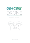
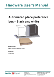
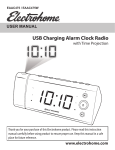
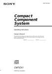
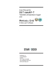
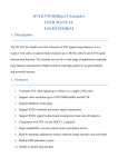
AVG-HDWP70RX
Features
AVG-AVG-HDWP100RX Wall Plate Receiver is
a Decora style HDBaseT receiver that installs in
a double-gang wall plate to provide a
convenient interface for HDMI / DVI output.
High bandwidth: 10.2Gbps
Wide resolution range (from 480p to
4Kx2K)
Compliant with HDMI 1.4, supports
1080p 3D
HDCP compliant, equipped with
HDCP auto-tracking
Bi-directional IR& RS232 control
Powered by local power pack or
power sourcing equipment via PoC/
PoE solution
Aluminum design for efficient cooling
AVG-HDWP70RX
PLEASE READ THIS PRODUCT MANUAL CAREFULLY
BEFORE USING THIS PRODUCT.
This manual is only for operation instruction only, and
not to be used in a maintenance capacity. The
functions described in this version are current as at
March 2015. Any changes of functions and
operational parameters will be updated in future
manual versions. Please refer to your dealer for the
latest product details.
Version 1.0 1/3/15
AVG-HDWP70RX
SAFETY OPERATION GUIDE
In order to guarantee the reliable operation of the equipment and safety of the
user, please abide by the following procedures in installation, use and
maintenance:
1. The system must be earthed properly. Please do not use two blade plugs
and ensure the AC power supply ranges from 100v to 240v and from 50Hz
to 60Hz.
2. Do not install the switcher in an environment where it will be exposed to
extreme hot or cold temperatures.
3. This unit will generate heat during operation, please ensure that you allow
adequate ventilation to ensure reliable operation.
4. Please disconnect the unit from mains power if it will be left unused for a
long time.
5. Please DO NOT try to open the casing of the equipment, DO NOT attempt to
repair the unit. Opening the unit will void the warranty. There are high
voltage components in the unit and attempting to repair the unit could result
in serious injury.
6. Do not allow the unit to come into contact with any liquid as that could result
in personal injury and product failure.
AVG-HDWP70RX
TABLE OF CONTENTS
Introduction .............................................................................................................. 1
Introduction to the AVG-HDWP70RX ........................................................... 1.1
Features ....................................................................................................... 1.2
Package List ................ ……………………………………………………………………2
Product Appearance ................................................................................................ 3
Front Panel ................................................................................................... 3.1
Rear Panel.................................................................................................... 3.2
System Connection .................................................................................................. 4
System Application ....................................................................................... 4.1
Usage Precautions ....................................................................................... 4.2
Connection Diagram ..................................................................................... 4.3
Connection Procedure .................................................................................. 4.4
PoC/PoE Solution ......................................................................................... 4.5
Specification ............................................................................................................. 6
Panel Drawing .......................................................................................................... 7
Troubleshooting & Maintenance ............................................................................. 8
AVG-HDWP70RX
1. Introduction
1.1. Introduction to the AVG-HDWP70RX
AVG-HDWP70RX Wall Plate Receiver is a Decora style HDBaseT receiver that
installs in a double-gang wall plate to provide a convenient interface with HDMI / DVI
output. It has 1 HDMI OUT, 1 HDBT IN with PoC & PoE, 2 IR IN and 1 IR OUT. It
supports HDMI 1.4& HDCP for reliable transmission. HDBT IN is capable of
receiving the AV& control signal from up to 70min distance, of which the IR & RS232
control signals can travel bi-directionally.
With its PoC/ PoE solution, HDBaseT Wall Plate Receiver can be powered by a farend device which supports PoC/ PoE.
1.2. Features
High bandwidth: 10.2Gbps
Wide resolution range (from 480p to 4Kx2K)
Compliant with HDMI 1.4, supports 1080p 3D
HDCP compliance, equipped with HDCP auto-tracking
Bi-directional IR& RS232 control
Powered by local power pack or power sourcing equipment via PoC/ PoE
solution
Aluminum design for efficient cooling
AVG-HDWP70RX
2. Package List
1 x AVG-HDWP70RX Wall Plate Receiver
2 x Screws (for AVG-HDWP70RX Wall Plate Receiver)
1 x Face Plate (2 gang)
2 x Screws (for face plate)
4 x Pluggable Terminal Blocks (2 2-pin block, 2 3-pin block)
1 x Power Adapter (DC 12V 1A, selectable)
1 x User Manual
Note: Please confirm if the product and the accessories are all included, if not,
please contact your dealer.
AVG-HDWP70RX
3. Product Appearance
3.1. Front Panel
No.
①
②
Name
Power
indicator
HDMI OUT
③
LINK &HDCP
④
IR
Description
Illuminates red when powered on
Connect with HDMI display
LINK: Twisted Pair Link status indicator, illuminates
green when successfully connected.
HDCP: HDCP compliance indicator, illuminates
green when the source signals contains HDCP;
blinks when HDCP not present. Turns off when there
is no source signal.
In-built IR sensor
Note: Pictures shown in this manual are for reference only.
AVG-HDWP70RX
3.2. Rear Panel
No.
Name
Description
①
PoC IN&
HDBT IN
RJ45 port, connect with transmitter via a CAT5e/6 cable to
deliver AV& control signals, supports PoC.
②
IR IN
Connect with IR receiver, receives IR signals sent from the IR
Emitter connected to the far-end receiver
③
IR OUT
Connect with IR Emitter, IR signals emitted from the IR emitter
are received by the IR receiver connected to the far-end
receiver.
④
RS232
Serial port, connects with a far-end receiver, supports bidirectional RS232 control (send control signal from local or
receive control signal sent from far-end devices).
⑤
Power
Connect with DC 12V power adapter
Note: Pictures shown in this manual are for reference only.
Note:
1. AVG-HDWP70RX Wall Plate Receiver can be powered via standard PoC &
PoE, i.e. it can be powered by a far-end device.
2. When connecting an IR Receiver to the IR IN socket, both the in-built IR
sensor and the extended IR Receiver is capable to receive IR signal.
3. Pictures shown in this manual are for reference only, different models and
specifications are subject change.
AVG-HDWP70RX
4. System Connection
4.1. System Applications
Reliable performance for control and transmission makes the AVG-HDWP70RX ideal
in the IT computer space, signal monitoring, big screen displays, conference
systems, television broadcast, education, banking and security institutions etc.
4.2. Usage Precautions
1. System should be installed in a clean environment with temperature and humidity
maintained to within equipment specification.
2. All of the power switches, plugs, sockets and power cords should be insulated
and safe.
3. All devices should be connected before power is turned on.
4.3. Connection Diagram
Note: Pictures shown in this manual are for reference only.
AVG-HDWP70RX
4.4. Connection Procedure
Step 1. Connect HDMI source device (e.g. Blu-ray DVD) to HDMI IN socket of
the HDBaseT Twisted Pair PoC Transmitter with HDMI cable.
Step 2. Connect the HDBT ports of HDBaseT Twisted Pair PoC Transmitter
and HDBaseT Wall Plate Receiver.
Step 3. Connect a HDMI display to the HDMI OUT port of HDBaseT Wall Plate
Receiver.
Step 4. Connect a control device (e.g. a PC) to the RS232 port of either
HDBaseT Twisted Pair PoC Transmitter or HDBaseT Wall Plate
Receiver.
Step 5. Both HDBaseT Twisted Pair PoC Transmitter and HDBaseT Wall Plate
Receiver have IR IN and IR OUT sockets. When one model is used as
the IR signal receiver, the IR signal must be sent out by the other
model.
For example: When “IR IN” of HDBaseT Wall Plate Receiver connects with an
IR receiver, the IR emitter must connect to IR OUT of HDBaseT
Twisted Pair PoC Transmitter.
Step 6. Connect a DC 24V power adaptor to the power port of HDBaseT
Twisted Pair PoC Transmitter.
Note: IR& RS232 signal can be transmitted bi-directionally between HDBaseT Wall
Plate Receiver and HDBaseT Twisted Pair PoC Transmitter.
AVG-HDWP70RX
4.5. PoC/ PoE Solution
Apart from power supply, AVG-HDWP70RX Wall Plate Receiver can be energized
by far-end devices that support PoC/ PoE, which increases the system flexibility.
Connect the receiver and far-end device (exampled by HDBaseT Twisted Pair PoC
Transmitter) via a CAT5e/6 cable as below:
Note: Pictures shown in this manual are for reference only.
AV, IR& RS232 control signals can also be transmitted via the cable.
Note: AVG-HDWP70RX Wall Plate Receiver supports unidirectional PoC/ PoE, i.e,
AVG-HDWP70RX Wall Plate Receiver can get power from a far-end PoC/ PoE
device.
AVG-HDWP70RX
6. Specification
Input
Input
Connector
Transmission
Distance
1 HDBT
1 RJ45
Video
Output
1 HDMI
Output
1 19-pin Type A HDMI female
Connector
1080P≤20M
4Kx2K≤15M
Control Parts
1 RS232
2 IR IN (1 in-built IR sensor on front panel, 1 3.5mm IR IN on rear
Control Ports
panel
1 IR OUT
General
HDMI:4Kx2K, 1080P 3D, 1080P, 1080i, 720P, 576P, 576i, 480P,
480i
DVI:1920x1200@60Hz, 1920x1080@60Hz, 1600x1200@60Hz,
Resolution
1280x1024@75Hz, 1280x1024@60Hz, 1024x768@75Hz,
1024x768@70Hz, 1024x768@60Hz, 800x600@75Hz,
800x600@72Hz, 800x600@60Hz, 640x480@75Hz,
640x480@72Hz, 640x480@60Hz
Transmission 1080P≤70M (PoC)
Distance
4Kx2K≤40M (PoC)
Bandwidth
10.2Gbps
HDMI
Supports HDMI1.4 and HDCP
Standard
Chassis
Decora style two gang
Dimension
Power
Power
7w (Max)
DC 12V 1A
Consumption
Supply
Reference
Temperature 0 ~ 55℃
10% ~ 90%
Humidity
Dimension
89x 104 x 35
Weight
0.24Kg
(W*H*D)
mm
AVG-HDWP70RX
7. Panel Drawing
Note: Pictures shown in this manual are for reference only.
AVG-HDWP70RX
8. Troubleshooting & Maintenance
Problems
Color loss or no
video signal output
in the HDMI display
No HDMI signal
output in the device
while local HDMI
input is in normal
working state
Causes
Solutions
The cables may be
incorrectly
connected or faulty
Check whether the cables are
connected correctly and in good
working condition.
Loose or failed
power cord
connection
Ensure the power cord connection is
good
Wrong RS232
communication
parameters
Make sure the RS232
communication parameters are
correct.
The unit is faulty
Send it to authorized dealer for
repairing.
Poor grounding
Check the grounding and make sure
it is connected well.
Output image is
noisy
POWER indicator
doesn’t work or
respond to any
operation
Cannot control the
device by control
device (e.g. a PC)
through RS232 port
Static becomes
stronger when
connecting the
video connectors
If your problem persists after following the above troubleshooting steps, seek
further help from authorized dealer.