1
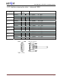
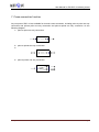
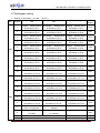
User Manual for PW-DXC-16 tributary board
Appendix
Please read this instruction manual carefully
before using the devices.
Instruction Manual
PW-DXC-16 Tributary Board
User Manual for PW-DXC-16 tributary board
Contents
1. System Introduction ................................................................................................................................. 3
1.1. Summary: ...................................................................................................................................... 3
1.2. Functions and features .................................................................................................................. 3
1.3. Technology Parameter: ................................................................................................................. 3
2. Front view of DXC-16 tributary board ...................................................................................................... 4
3. Meaning of LED signal light on panel of DXC-16 .................................................................................... 4
4. Structure of DXC-16 Tributary board ....................................................................................................... 5
5. E1 interface line outgoing chart (unbalanced 75Ω) ................................................................................. 5
6. E1 interface outgoing line chart:(balanced 120Ω) ............................................................................... 6
7. Cross-connection function ....................................................................................................................... 7
8. Switchgear setting ................................................................................................................................... 8
9. Clock setting ............................................................................................................................................ 9
10. Solutions and Service Center ................................................................................................................ 9
www.pacificwave-wireless.com
Page 2
User Manual for PW-DXC-16 tributary board
1. System Introduction
1.1. Summary:
DXC-16 Digit-cross connection equipment is featured with high density, easy operation, perfect
management and maintenance function, realizing effective management of transmission network. It
provides flexible exchange network and supports 64K signal channel’s non-blocking cross connection
of any E1.This equipment possesses processing capacity of channel associated signaling.
User can deploy capacity of equipment flexibly, eight E1 or sixteen E1 are available. Synchronous
clock can be extracted through circuit or by the equipment.
1.2. Functions and features
The minimum resolution of cross-connection is 64Kbit/s;
Provides 16 basic group interface which confirms to the suggestion of ITU-T G.703;
The impedance is 120Ω or 75Ω;
Provides local monitoring interface(RS232, RS485);
Provides internal channel, realizing remote operation and control;
Arbitrary broadcasting capacity of internal time slots;
Cross-connection of channel associated signaling;
DC-48V or AC 220V is optional;
With processing capacity of digit signal process, signaling process, and so on.
1.3. Technology Parameter:
Interface Signaling Rate Level: E1(2048Kbps)
Working Temperature: 0℃~40℃
Relative Humidity: less than 85%(+25℃),with no condensation
Power Supply: DC-48V or AC220V
Power: ﹤20W
Ventilation Condition: natural ventilation
Cross BAR: 512 bidirectional
Signal transmission time skew:﹤600us
CAS signal delay:﹤7ms
Basic group interface number:16
Interface impedance: 75Ω/120Ω
Physical electrical property: confirms to G.730 standard
Framing structure: Confirms to G.704 and G.706 standard
Precision of internal clock: ±50ppm
www.pacificwave‐wireless.com Page 3 User Manual for PW-DXC-16 tributary board
2. Front view of DXC-16 tributary board
RUN
NET
LOF
LOS
AIS
DA
MDA
MLOF
E1/2
E1/1
E1/4
E1/6
E1/4
E1/5
E1/8
E1/7
E1/10
E1/9
E1/12
E1/14
E1/11
E1/13
E1/16
E1/15
3. Meaning of LED signal light on panel of DXC-16
Each tributary board is designed with perfect alarm and indication function. Refer to the following chart
for its function and indication meaning.
LED title
Meaning of signal light
Color
RUN
Power is normal: twinkling
Green
NET
Invalid
Green
LOF
When receiving signal is out of step: lighted
Red
LOS
When inputting signal is lost: lighted
Red
AIS
When receiving signal are all “1”: lighted
Yellow
DA
When remote device alarms: lighted
Yellow
MDA
When opposite device framing alarming: lighted
Yellow
MLOF
When occurs Multi-frame out-of-sync: lighted
Red
E1/1-E1/16
When channel is occupied: it is lighted and then
goes out.
Red
www.pacificwave‐wireless.com Remarks
Detailed
alarm
indication:
( detailed alarm of a E1
is set through 1 to 6 of
SW1
and
SW2.For
example, if the 3rd seat
of SW1 is ON, then the
detailed
information
comes from E1/3 )
Indication
when
sub-channel is occupied.
Page 4 User Manual for PW-DXC-16 tributary board
4. Structure of DXC-16 Tributary board
E1/13-E1/16
DB37-CC4/16 converter
E1/9-E1/12
(E1/9~E1/16
interface)
E1/5-E1/8
DB37-CC4/16 converter
SW1
E1/1-E1/4
(E1/1~E1/8
interface)
SW2
5. E1 interface line outgoing chart (unbalanced 75Ω)
1)With DB37-CC4-16 converter,
ports of E1/9~E1/16 are as the following diagram:
th
The 16 E1 interface
The 12th E1 interface
th
The 15 E1 interface
The 11th E1 interface
th
The 14 E1 interface
The 10th E1 interface
th
The 13 E1 interface
The 9th E1 interface
8
7
6
5
4
3
2
1
Out In
2)With DB37-CC4-16 converter, ports of E1/1~E1/8 are as the following diagram:
th
The 8 E1 interface
The 4th E1 interface
th
The 7 E1 interface
The 3rd E1 interface
th
The 6 E1 interface
The 2en E1 interface
th
The 5 E1 interface
The 1st E1 interface
8
7
6
5
4
3
2
1
Out In
www.pacificwave‐wireless.com Page 5 User Manual for PW-DXC-16 tributary board
6. E1 interface outgoing line chart:(balanced 120Ω)
E1 interface
E1-1
E1-2
E1-3
E1-4
E1-5
E1-6
E1-7
E1-8
Definition
DB37
needle
number
Remarks
Receive
3
21
3:RRING
21:RTIP
transmit
22
4
22:TRING
4:TTIP
Receive
7
25
7:RRING
25:RTIP
transmit
26
8
26:TRING
8:TTIP
Receive
11
29
11:RRING
29:RTIP
transmit
30
12
30:TRING
12:TTIP
Receive
15
33
15:RRING
33:RTIP
transmit
34
16
34:TRING
16:TTIP
Receive
5
23
5:RRING
23:RTIP
transmit
24
6
24:TRING
6:TTIP
Receive
9
27
9:RRING
27:RTIP
transmit
28
10
28:TRING
10:TTIP
Receive
13
31
13:RRING
31:RTIP
transmit
32
14
32:TRING
14:TTIP
Receive
17
35
17:RRING
35:RTIP
transmit
36
18
36:TRING
18:TTIP
母头 连接器
DB37-F Connecter
www.pacificwave‐wireless.com Page 6 User Manual for PW-DXC-16 tributary board
7. Cross-connection function
Any two ports of DXC-16 are available for time slot cross-connection, including point-to-point one way
connection and point-to-point two-way connection and point-to-points one way connection. As the
following diagram:
1) point-to-point one way connection:
2) point-to-points two-way connection:
3)
4) point-to-points one way connection
www.pacificwave‐wireless.com Page 7 User Manual for PW-DXC-16 tributary board
8. Switchgear setting
1)Settings of switchgear(0 is ON,1 is OFF)
SW.
Default
setting
ON
OFF
1
Display detailed alarm
information of E1/1
Not display detailed alarm
information of E1/1
Display detailed alarm
information of E1/1
OFF
2
Display detailed alarm
information of E1/2
Not display detailed alarm
information of E1/2
Display detailed alarm
information of E1/2
OFF
3
Display detailed alarm
information of E1/3
Not display detailed alarm
information of E1/3
Display detailed alarm
information of E1/3
OFF
4
Display detailed alarm
information of E1/4
Not display detailed alarm
information of E1/4
Display detailed alarm
information of E1/4
OFF
5
Display detailed alarm
information of E1/5
Not display detailed alarm
information of E1/5
Display detailed alarm
information of E1/5
OFF
6
Display detailed alarm
information of E1/6
Not display detailed alarm
information of E1/6
Display detailed alarm
information of E1/6
OFF
7
Display detailed alarm
information of E1/7
Not display detailed alarm
information of E1/7
Display detailed alarm
information of E1/7
OFF
8
Display detailed alarm
information of E1/8
Not display detailed alarm
information of E1/8
Display detailed alarm
information of E1/8
OFF
9
Display detailed alarm
information of E1/9
Not display detailed alarm
information of E1/9
Display detailed alarm
information of E1/9
OFF
10
Display detailed alarm
information of E1/10
Not display detailed alarm
information of E1/10
Display detailed alarm
information of E1/10
OFF
1
Display detailed alarm
information of E1/11
Not display detailed alarm
information of E1/11
Display detailed alarm
information of E1/11
OFF
2
Display detailed alarm
information of E1/12
Not display detailed alarm
information of E1/12
Display detailed alarm
information of E1/12
OFF
3
Display detailed alarm
information of E1/13
Not display detailed alarm
information of E1/13
Display detailed alarm
information of E1/13
OFF
4
Display detailed alarm
information of E1/14
Not display detailed alarm
information of E1/14
Display detailed alarm
information of E1/14
OFF
5
Display detailed alarm
information of E1/15
Not display detailed alarm
information of E1/15
Display detailed alarm
information of E1/15
OFF
6
Display detailed alarm
information of E1/16
Not display detailed alarm
information of E1/16
Display detailed alarm
information of E1/16
OFF
7
System uses internal
clock of equipment
System clock is selected by
software
OFF
8
Framing mode of device
is PCM31
Framing mode is selected
by software
OFF
SW1
SW2
Priority rating
Number
9
Invalid
OFF
10
Invalid
OFF
www.pacificwave‐wireless.com Page 8 User Manual for PW-DXC-16 tributary board
Any detailed alarm information of E1/1~E1/16 can be displayed through switchgear SW1 AND SW2.
Each time display one E1 alarm information; If there are many E1 require to display, E1 with higher
level prevails.
9. Clock setting
The equipment is furnished with internal clock or link clock. When choosing internal clock, the
precision is ±50PPM. When choosing link clock, DXC-16 can be synchronous with any E1 clock of E1
interface from 1 to 16.
1) Set the 7th seat of SW2 to ON, the system uses the internal clock provided by equipment;
2) Set the 7th seat of SW2 to OFF, the system clock is determined by software, any E1 clock of E1
interface from 1 to 16.
www.pacificwave‐wireless.com Page 9