1
38687
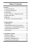
VOICE/DATA CSU
38687
POWER
LOOPBACK
SIG
SYNC
XMT
RCV
BUSY BUSY
USER'S MANUAL
VOICE/DATA CSU
TxD
RxD
RTS CTS
TECHNICAL PUBLICATION A98-110000
REVISION C
October 2001
WARNING
This equipment generates, uses, and can radiate radio frequency energy, and if not installed and used in
accordance with the instruction manual, may cause interference to radio communications. It has been tested
and found to comply with the limits for a Class A computing device pursuant to Subpart J of Part 15 of FCC
Rules, which are designed to provide reasonable protection against such interference when operated in a
commercial environment. Operation of this equipment in a residential area may cause interference, in which
case the user, at his own expense, will be required to take whatever measures may be necessary to correct
the interference, including possible disconnection of the equipment.
All rights reserved. Printed in USA.
TABLE OF CONTENTS
1.
2.
3.
4.
5.
6.
7.
8.
9.
10.
11.
12.
13.
GENERAL
FEATURES AND BENEFITS
APPLICATIONS
INSPECTION AND INITIAL SELF TEST
INSTALLATION
DIP SWITCH SETTINGS
FRONT PANEL INDICATORS AND CONTROL
VOICE OPERATION
DATA OPERATION
TEST MODES AND MAINTENANCE
WARRANTY
REPAIR AND RETURN PROCEDURES
SPECIFICATIONS
1
1
4
5
6
8
13
14
16
19
21
21
22
1. GENERAL
The 38687 is a Voice and Data CSU designed to operate over dedicated (leased) 56 Kbps
or 64 Kbps digital telephone lines. The 38687 provides two user interfaces (one voice, one data),
which can be used simultaneously and continually over a single digital leased line. These two inputs are
derived from a multiplexed signal transmitted and received over a standard 56 Kbps or 64 Kbps digital data
telephone line. Such 56 or 64 Kbps lines are standard types throughout North America, and are provided by
local telephone companies or long distance carriers, under services known as Dataphone Digital Service
(DDS), Basic Digital Service (BDS), Accunet Spectrum of Digital Services, Sprint Clearline, and equivalents.
The 38687 Voice/Data CSU can be used with telco provided lines, or in private networks for high
speed, point-to-point applications requiring both voice and data connectivity.
The 38687 advanced design, compact size, and reliability make it an ideal product for most
applications requiring the transmission of simultaneous voice and data over a single dedicated digital facility.
2. FEATURES AND BENEFITS
* SIMULTANEOUS VOICE AND DATA OPERATION
The unit operates continually over a single standard 56 or 64 Kbps digital telephone line on the
network side, and provides one sync or async data connection and one voice telephone type connection on
the customer (user) side. The two user interfaces (one voice, one data) are independent of each other, and
may be operated simultaneously over the single digital telephone line. No blocking or slowdown of data or
throughput will occur.
1
* AUTOMATIC BANDWIDTH OPTIMUMIZATION FOR DATA
The 38687 can be user configured for "MAXimum bandwidth utilization" so as to utilize as
much of the 56 Kbps or 64 Kbps digital line for data as possible, when the voice channel is not in use. This
user selection option provides nearly the entire digital bandwidth for the data whenever the voice channel is
in the idle, or "on hook", condition.
* STANDARD INTERFACE CONNECTORS
The unit contains an RJ-48S type modular telco connector for the line interface, and a standard DB25 connector for the data interfaces on the customer side. The voice interfaces are of two types, two-wire
loop signaling, or two-wire/four-wire E&M. The two-wire loop signaling user port is terminated through a
standard RJ-11C type modular jack, while the two-wire/four-wire E&M voice channel is terminated through
an eight wire RJ-45X type modular jack. Only one of the two voice channel connections is active at any one
time. All the customer connections to the 38687 are made through easily accessible connectors on
the rear panel of the unit.
* FLEXIBLE RANGE OF VOICE INTERFACES
The 38687 provides several varieties of interfaces for its single voice circuit. The unit may be
provisioned to provide a standard telephone interface for dial-up access (Foreign Exchange- Subscriber,
FXS mode), direct connection to a PBX line port or outside telco provided line (Foreign Exchange - Office,
FXO mode), automatic ringdown from telephone to telephone (Private Line Automatic Ringdown, PLAR
mode), or the unit may be configured to provide an analog voice tie trunk between two Private Branch
Automatic Exchanges (PABX, 2W/4W E&M interface). Each mode is selected by a single switch setting
located conveniently on the rear panel of the unit. The 38687 is compatible with virtually all telephone sets,
private automatic branch exchanges (PBX), and telco provided standard telephone lines.
* FLEXIBLE CHOICE OF DATA INTERFACES
The 38687 offers a wide range of choices for the data interface on the customer side. The
data channel may operate at speeds of 9.6, 14.4, 19.2, 28.8, or 38.4 Kbps either synchronously or
asynchronously. Additionally, lower asynchronous speeds are supported by digital over-sampling, and
higher synchronous rates can be supported when the voice channel is idle, to maximize throughput for LANto-LAN traffic. The physical interface is through a DB-25 type connector, which can be user configured to
provide either an RS-232, RS-530/RS-422, or V.35 type of interface electrically. Additionally, the data
channel may be optioned for either sync or async operation, and the user may select either DTE or DCE
transmit clock when in synchronous mode. When in synchronous mode, the 38687 is independent of
both data protocol and format. In all cases, the data circuit is independent of traffic type and protocol.
* AUTOMATIC ADAPTIVE EQUALIZATION FOR TELCO SIDE
The adaptive equalization circuitry automatically compensates for distance and line quality of the 56
or 64 Kbps digital line, which allows the unit to work error-free in normal environments without adjustments.
Generally, the unit need only be plugged into the telco provided modular service jack to begin to transmit
and receive information properly.
* INTEGRAL CLOCK GENERATOR
The 38687 Voice/Data CSU offers two timing modes for synchronization; DDS (Looped)
timing from the network, derived from the received signal on the 4-wire loop, or Internal (Int) timing via an
internal crystal oscillator. This offers flexibility by allowing the unit to work in public network applications, as
well as for use in point-to-point private applications.
2
* EXTENSIVE DIAGNOSTIC CAPABILITIES
The 38687 offers several test modes for diagnostic purposes. It can perform several types of
loopbacks, designed to isolate and identify faults within the entire network. The unit can be placed in a Local
Loopback mode, which removes it from the external telephone network, and causes the data and voice
channels to be looped back upon themselves. This provides a simple means for testing the 38687 for
proper operation. The Remote Loopback mode sends a unique signal to the far end 38687, causing it
to present a loopback towards the network and back to the near end. This enables the user to test the
telephone circuit all the way to the far end multiplexer. Simple status lamps on the front of the unit indicate
proper operation. Also, the 38687 responds to all standard network generated loopback patterns and signals,
at both 56 and 64 Kbps line rates, so that the telephone company can initiate diagnostic tests and assist in
the resolution of problems with the circuits when necessary. All tests are simple to operate and easy to
interpret.
* USE OF VLSI TECHNOLOGY
The 38687 utilizes Very Large Scale Integration (VLSI) technology in the form of state of the
art microprocessors and Field Programmable Gate Arrays (FPGAs) to insure high reliability, maximum
performance, low power consumption, and compact size. This maximizes reliability and minimizes the need
for spares.
* FRONT PANEL LED'S/CONTROL
The front panel holds 10 LED'S and one LOOPBACK switch for quick identification of all status
conditions, and convenient selection of test modes.
* COMPACT SIZE
The unit is physically compact, light, and is contained in a housing made of durable plastic,
designed to sit on a desktop or in an equipment room. The 38687 will operate in a broad range of
environmental conditions, and requires minimal space and no special power or cooling. Power for the 38687
is derived from a standard AC wall outlet.
* EASY INSTALLATION
The 38687 is designed for easy installation and operation. No trained personnel are needed
to install or activate the unit. All connections are of a plug-in, connectorized type, and are made on the rear
of the unit. The unit is optioned via two "DIP" switches located on the rear panel. No alignments or
adjustments are required.
* LOW POWER CONSUMPTION
The unit has a low power consumption and uses an external wallmount power supply (supplied with
unit) which plugs into a standard 120 V, 60 HZ or 220 V, 50 Hz grounded outlet. Due to the low power
consumption of the 38687, the unit has no cooling fans or moving parts, further enhancing reliability.
* TWO-YEAR STANDARD WARRANTY
The 38687 Voice/Data CSU has a standard two-year or optional five year limited warranty,
which covers parts and labor under normal operating conditions. Should service or repair be necessary,
contact:
Black Box
(724) 746-5500
3
3. APPLICATIONS
56/64 Kbps Digital Line
38687
POWER
LOOPBACK
SIG
SYNC
XMT
RCV
BUSY BUSY
VOICE/DATA CSU
TxD
RxD
RTS CTS
38687
POWER
38687
Voice/Data CSU
LOOPBACK
SIG
SYNC
XMT
RCV
BUSY BUSY
VOICE/DATA CSU
TxD
RxD
RTS CTS
38687
Voice/Data CSU
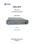
Remote Site
Main Site
Typical Installation
Figure 1
The 38687 Voice/Data CSU provides end-to-end connectivity for one voice circuit and one data circuit
over a standard 56 Kbps or 64 Kbps digital telephone line, such as provided by local telephone companies
(Basic Digital Services), and long distance carriers (Digital Data Service, Accunet Spectrum of Digital
Services, etc). In these applications, the 38687 operates in "looped" timing mode, deriving its timing
from the network for purposes of synchronization. Connection to the network is via a standard RJ-48S
type modular jack.
The 38687 connects to DTE (Data Terminal Equipment) via the DB-25 interface connector mounted
on the rear panel of the unit. The DTE can be one of many devices, such as computer mainframes, minicomputers, workstations, CAD/CAM equipment, multiplexers, LAN bridges, video display terminals, video
conferencing equipment, high speed printers, etc. Typical applications include connection of terminals at a
remote location to a mainframe at a central location, or connections of a remote PC to a LAN. See
4
accompanying diagrams. The 38687 is a time division unit, whose operation is independent of traffic density
or data usage. The 38687 provides a data connectivity "pipeline" for the data channel, extended over the 56
Kbps or 64 Kbps facility.
The 38687 connects to voice telephone equipment through either an RJ-11C type (six pin) modular
jack, or an RJ-45X type (eight pin) modular jack, located on the rear panel of the unit. The single voice circuit
of the 38687 can provide end-to-end connectivity a single standard telephone circuit with loop signaling
(ringing and dialing) control, or a PBX-to-PBX tie trunk with E&M signaling control. Typical applications are
for remote connection of a telephone to a PBX station circuit (off-premise station), or remote connection to
an outside telephone line (off-premise extension). The 38687 can also be used to support FAX or analog data
transmission between two facilities, or can support a point-to-point voice ringdown circuit ("hot line"). When
used to connect a phone at a remote location to the PBX at the central location, the 38687 provides a means
for the remote user to have an extension of the PBX, equivalent to those on-site. The use of Adaptive
Differential Pulse Code Modulation (ADPCM) in the 38687, allows the 38687 to provide the
unique feature of user selectable voice quality, based upon the user's needs for both voice quality and for
data speed and throughput. The voice circuit can be provisioned to use 16 Kbps (good), 24 Kbps (better), or
32 Kbps (best) voice coding. The more bandwidth selected for the voice coding, the better the voice quality
for the voice channel, but less bandwidth remains to be used by the data channel. The user has the option
of deciding which combination of voice coding and data speeds best fits his application needs. The use of
ADPCM voice coding provides for a high quality voice connection with minimum transmission delay. The
38687 contains all the equipment necessary for all voice and signaling applications, including the generators
of the ringing and talk battery signals.
The 38687 can also be used in private, point-to point network applications (see figures), providing
access over any four-wire (two twisted pairs) facility. When used in a private, point-to-point application, the
unit provides its own clock synchronization via the integral clock generator (Internal timing mode).
4. INSPECTION AND INITIAL SELF TEST
Upon receipt of the equipment, visually inspect it for signs of damage. Immediately report any damage to the
transportation company and to the supplier. Then perform the following quick and simple self-tests:
1. Before connecting any of the telco or voice or data cables, plug the male connector at the small
end of the cord of the external wallmount power supply (supplied with the unit) into the
female receptacle marked POWER on the rear of the 38687. Then plug the
wallmount power supply line cord into any standard grounded 110/220 VAC outlet.
2. Observe the front panel LED's (light emitting diodes). The LED marked POWER should be
illuminated. All other LEDs should not be lit.
3. Next place the front panel switch marked LOOPBACK in the position marked LOC (left). The
LED next to the switch, and the LED marked SYNC should illuminate. This basically
indicates normal operation of the unit. Place the LOOPBACK switch back to its normal
(center) position.
4. Next connect the unit to the telephone line using the modular cord supplied with the unit. The unit
should be functional when plugged directly into the modular jack supplied from the
telephone company. If a valid signal is received by the 38687 from the digital
telephone line, the LED marked SIG will light. Having done this, the 38687 is ready for
connection to the customer side equipment, per the next section, INSTALLATION.
5
5. INSTALLATION
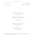
POWER NETWORK
RJ48S
VOICE S1
1 2 3 4 5 6 7 8 9 10
10
E&M
LOOP
RJ11
UNIVERSAL DATA PORT
DATA S2
1 2 3 4 5 6 77 88 99 10
FIGURE 3
Installation of the 38687 requires no special tools, adjustments, or measurements. Installation of the
38687 consists of properly setting the two ten position "DIP" switches (S1 and S2) located on the rear
panel of the unit, and connecting the voice and data equipment to the connectors on the unit's rear panel.
Connection to the telephone network is accomplished by connecting the unit to the modular jack supplied by
the telephone company, using the modular cord supplied with the unit. The Adaptive Distance Equalization
circuitry of the 38687 compensates for distance and line quality automatically, eliminating the need for
adjustments. Installation of the voice and data equipment is accomplished by first setting the two DIP
switches to their appropriate settings per Section 6 below, and then connecting the data equipment to the
38687 by connecting an appropriate data type cable, with a 25 pin DB-25 connector, to the DB-25
type connector, marked DATA, located on the rear of the unit. The voice equipment is connected by using a
standard six or eight wire modular cord to connect from the jacks marked LOOP or E&M on the rear of the
unit to the appropriate jacks of the telephone set, PBX, or outside line to which the 38687 is to be
connected. The wiring plan of the modular jacks and of the DB-25 connectors follows the standard
conventions. The telephone line jack is of the RJ-48S type and is wired as follows:
Transmit pair
Receive pair
Pins 1 & 2
Pins 7 & 8
The DB-25 connector for the data connections follows the convention for DCE equipment, and can be
configured by the user to provide the electrical characteristics of an RS-232, RS-530, or V.35 interface.
When configured as an RS-232 or an RS-530 interface, only a standard "straight through" cable is required
to connect the 38687 data channel to DTE equipment. When the data channel interface is configured
for V.35, or if the user wishes to connect the 38687 to an RS-422 DTE interface, an adapter cable is
required, which can be purchased separately from Black Box. In particular, the 25-pin DB-25 data connector
is wired as follows:
6
Transmit Data (TxD)
Transmit Clock (TC)
External Transmit Clk (ETC)
Data Terminal Ready (DTR)
Request to Send (RTS)
Receive Data (RxD)
Receive Clock (RC)
Clear to Send (CTS)
Data Set Ready (DSR)
Carrier Detect (CD)
Signal Ground (SG)
Protective Ground (PG)
Ring Indicator (RI)
RS-232
RS-530
V.35 (Via Adaptor Cable)
Pin 2
Pin 15
Pin 24
Pin 20
Pin 4
Pin 3
Pin 17
Pin 5
Pin 6
Pin 8
Pin 7
Pin 1
Pin 22
Pins 2 & 14
Pins 12 & 15
Pins 11 & 24
Pin 20
Pin 4 & 19
Pins 3 & 16
Pins 9 & 17
Pin 5 & 13
Pin 6
Pin 8 & 10
Pin 7 & 23
Pin 1
Pin 22
Pins P & S
Pins Y & AA
Pins U & W
Pin H
Pin C
Pins R & T
Pins V & X
Pin D
Pin E
Pin F
Pin B
Pin A
Pin J
The six-wire modular jack for the loop voice telephone connections are of the RJ-11C type, with the
following wiring:
Two-wire Pair (Tip & Ring)
Pins 3 & 4
The eight-wire modular jack for the E&M voice telephone connection is an eight-wire type with the following
wiring:
Two-wire Pair (2W) or Transmit Pair (4W)Pins 4 & 5
Receive Pair (4W only)
Pins 3 & 6
E-Lead
Pin 2
M-Lead
Pin 8
SG-Lead
Pin 7
MB-Lead
Pin 1
After you make the telco, voice, and data connections, the installation needs only the correct setting of the
DIP switches as described in the next section. The POWER LED should be on steady, and the SIG LED
should be lit, indicating a successful telephone line connection, and presence of the digital signal from the
network. If a 38687 is already connected to the telephone line at the far end, and is configured
properly, the SYNC LED should be lit, indicating the reception of a valid signal from the companion
38687 at the far end of the telephone digital line circuit.
After connection of the 38687 to the four-wire telephone line provided by the local carrier, the carrier
may request notification of the unit's registration for connection to the public network under the rules of the
Federal Communications Commission, Part 68. The registration number and other needed information for
the 38687 is as follows:
Registration Number: 5LYUSA-32793-DE-N
Type of Equipment: Equipment Providing CSU Functions Including Encoded Analog Content
7
6. DIP SWITCH SETTINGS
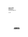
ON
1 2 3 4 5 6 7 8 9 10
Voice Switch 1
1 2 3 4 5 6 7 8 9 10
Data Switch 2
Figure 2
The 38687 comes from the factory with its DIP switches as shown in Figure 2. The two DIP switches,
S1 and S2, need to be properly set for each particular user's application. In general, the first DIP switch, S1,
controls the operation of the voice channel, and the second DIP switch, S2, controls the operation of the
data channel and the telephone line connection. Both DIP switches need to be set properly for the unit to
function correctly (see Figure 2).
The two DIP switches, S1 and S2, are located on the rear panel of the 38687. In general, the first DIP
switch, S1, controls the voice channel operation and levels, and the four-wire telco interface. Switch S1 is to
be set as follows:
8
S1-1, S1-2 These two switches control the operating mode of the voice channel of the 38687.
They are coded in such a way as to configure the 38687 for FXO, FXS,
PLAR, or E&M operation as follows:
S1-3
S1-1
S1-2
Voice Channel Mode
OFF
OFF
FXS
OFF
ON
FXO
ON
OFF
PLAR
ON
ON
E&M
When ON, S1-3 puts the voice channel in the 16 Kbps coding mode. This is the mode that
uses the least amount of bandwidth for the voice channel and allows for maximum speed of
the data channel. This voice coding selection will select GOOD voice quality.
When OFF, 16 Kbps voice coding (GOOD) is NOT selected.
S1-4
When ON, the voice channel is configured to operate in the 24 Kbps coding mode. This
choice of voice operation provides BETTER voice quality, while leaving less bandwidth
available for data speed. Choose this setting if you require improved voice quality, but
still wish to maintain a high data speed for your data channel.
When OFF, the 24 Kbps voice coding (BETTER) mode is NOT selected.
S1-5
When ON, the voice channel is configured to operate in the 32 Kbps coding mode. This
choice provides the BEST voice quality for the voice channel. This setting will provide "toll
quality" voice, and will allow for high-speed analog data and fax traffic over the voice
channel. However, this setting provides the least amount of bandwidth available to the data
channel, and limits the speed of the data circuit accordingly.
When OFF, the 32 Kbps voice coding (BEST) mode is NOT selected.
9
S1-6 & S1-7 These two switches configure the receive voice level of the voice channel when
the voice channel is operating in any two-wire mode. This includes FXO, FXS, PLAR,
and 2W E&M operation. When the 38687 is configured for 4W E&M operation,
these two switches are inactive. The two switches are coded to provide output receive
levels of 0 dBm, -3 dBm, -6 dBm, or - 9 dBm, as follows:
S1-8
S1-6
S1-7
Receive Output Level (2W)
OFF
OFF
0 dBm
OFF
ON
-3 dBm
ON
OFF
-6 dBm
ON
ON
-9 dBm
When ON, this switch selects 4W E&M operation of the voice channel.
When OFF, this switch selects 2W E&M operation of the voice channel. Switch S1-8 is
only active if E&M operation is chosen on S1-1 and S1-2.
S1-9
When ON, this switch selects 4W voice levels of -16 dBm transmit, and +7 dBm receive.
When OFF, this switch selects 4W voice levels of 0 dBm transmit, and -3 dBm receive.
This switch is only active when the voice channel of the 38687 has been
configured for 4W E&M operation.
S1-10 When ON, this switch selects Type II E&M signaling.
When OFF, this switch selects Type I E&M signaling. This switch is only active when the
38687 voice circuit has been configured for either 2W E&M or 4W E&M operation.
10
The second DIP switch, S2, controls the operation of the data channel and the digital line interface as
follows:
S2-1 & S2-2 These two switches control the data interface, and determine what electrical
interface is selected for the data channel. The two switches determine whether the data
channel interface is electrically RS-232, RS-530/RS-422, or V.35 as follows:
S2-1
S2-2
Data Channel Interface
OFF
OFF
RS-232
OFF
ON
RS-530/RS-422
ON
OFF
V.35
S2-3, S2-4, & S2-5 These three switches determine the selected data speed, and whether or
not the "MAXimum bandwidth allocation" feature is enabled. The correct setting of these
three switches selects the data channel operating speed to be 9.6, 14.4, 19.2, 28.8, or
38.4 Kbps, and whether or not the data speed is optimized when the voice channel is not
used. The switch operation is as follows:
S2-3
S2-4
S2-5
Data Speed
OFF
OFF
OFF
9.6 Kbps
OFF
OFF
ON
14.4 Kbps
OFF
ON
OFF
19.2 Kbps
OFF
ON
ON
28.8 Kbps
ON
OFF
OFF
38.4 Kbps
ON
OFF
ON
19.2, with MBA (Sync only)
ON
ON
OFF
28.8, with MBA (Sync only)
ON
ON
ON
38.4, with MBA (Sync only)
11
S2-6
When ON, selects External Transmit Clock to load the input buffer of the data circuit if in
synchronous data mode.
When OFF, selects the internal data clock (Transmit Clock) to load the input data buffer
of the data circuit when in synchronous data mode.
S2-7
When ON, selects ASYNCHRONOUS data operation for the Data Channel.
When OFF, selects SYNCHRONOUS data operation for the Data Channel.
S2-8
When ON, selects end-to-end flow control operation for the Data Channel.
When OFF, no end-to-end flow control is provided for the Data Channel.
S2-9
When ON, selects 56 Kbps line operation.
When OFF, selects 64 Kbps Clear Channel (72 Kbps line rate) line operation.
S2-10 When ON, Internal Line Timing is selected.
When OFF, Looped Line Timing is selected.
The following selections of voice and data are allowable combinations:
-------------------------------Valid Data Speeds--------------------------------------Voice Coding
56Kbps Line
64Kbps Line
16 Kbps (Good) 9.6, 14.4, 19.2, 28.8, 38.4 Kbps 9.6, 14.4, 19.2, 28.8, 38.4 Kbps
24 Kbps (Better) 9.6, 14.4, 19.2, 28.8 Kbps
32 Kbps (Best)
9.6, 14.4, 19.2 Kbps
9.6, 14.4, 19.2, 28.8, 38.4 Kbps
9.6, 14.4, 19.2, 28.8 Kbps
When an invalid combination of DIP switch settings is chosen, the LOOPBACK, SYNC, XMT BUSY, and
RCV BUSY front panel LEDs will FLASH continuously.
12
7. FRONT PANEL INDICATORS AND CONTROLS
38687
POWER
LOOPBACK
SIG
SYNC
XMT
RCV
BUSY BUSY
VOICE/DATA CSU
TxD
RxD
RTS CTS
Figure 4
The following describes the ten green LED indicators located on the front of the unit, and the operation of the
front panel rocker switch of the 38687.
Front Panel LEDs, as seen left to right:
POWER
When lit, this LED indicates that power is applied to the 38687 unit.
LOOPBACK
Located next to the LOOPBACK switch, this LED indicates that the 38687 is in
a loopback mode.
SIG
When lit, indicates a valid signal is being received by the 38687 at its receive
pair of the RJ-48S telephone line connection.
SYNC
When lit, indicates the 38687 receiver framing circuitry is receiving a valid
synchronizing signal from its companion 38687 unit at the far end, and is
properly aligned to the incoming multiplexed signal.
XMT BUSY
When lit, this LED indicates that a busy (off-hook) condition is being detected at
the local telephone voice interface. When this occurs, the 38687 sends an
off-hook indication to the far end unit, so that the proper signaling state can then
be provided to the voice equipment at that end of the circuit.
RCV BUSY
When lit, this LED indicates that the 38687 is receiving a busy (off-hook)
condition for the voice circuit from the 38687 unit at the far end of the
circuit. The 38687 then translates this indication of off-hook status into the
proper condition of the signaling circuits to the local telephone voice equipment.
TRANSMIT DATA (TxD) When lit, this LED indicates that the 38687 is receiving a SPACE
on its transmit data input (pin 2) from the DTE for its Data Channel, AND the Data
Terminal Ready lead (DTR, pin 20) for that channel is asserted.
When not lit, this LED indicates that the 38687 is receiving a MARK from the DTE on
its transmit data pin, OR the DTR lead from the DTE is not asserted.
13
RECEIVE DATA (RxD) When lit, this LED indicates the 38687 is sending a SPACE on
its receive data output (pin 3) to the DTE, AND Carrier Detect (CD, pin 8) is
asserted by the 38687 to the DTE.
When not lit, this LED indicates that the 38687 is sending a MARK to the DTE on the
receive data lead, OR Carrier Detect is low (not asserted), indicating a loss of valid
signal at the receiver of the 38687.
RTS
When lit, this LED indicates that the Request-to-Send (RTS) lead of the data
interface is asserted by the data terminal equipment.
CTS
When lit, this LED indicates that the Clear-to-Send (CTS) lead of the data interface
is being asserted towards the data terminal equipment by the 38687.
The front panel LOOPBACK switch is a rocker type with three positions. The center position is the NORMAL
position. When in this position, the 38687 operates normally, and will transmit and receive voice and
data information to and from the far end companion unit. When LOOPBACK is placed in the left position
(LOC), the 38687 is put into its local loopback condition. In this mode, the 38687s transmit 56 or 64 Kbps
information is looped back to its receiver, and an all-ones condition is transmitted to the far end unit. This
mode is used for troubleshooting and diagnostics, per Section 10 below. When LOOPBACK is placed in the
right (REM) position, the 38687 will send a unique loopback signal to the companion 38687 at the far end,
causing it to perform a network loopback back towards the local 38687 (see Section 10). Note that
when the LOOPBACK switch is either in the left (LOC) or right (REM) positions, the accompanying LED is lit,
indicating a loopback test condition. After 2 minutes, if the switch is left in these positions, the test is
terminated and the LED will go off, indicating the test has timed out.
8. VOICE OPERATION
The 38687 provides one voice channel (port) derived from the multiplexed 56 or 64 Kbps aggregate
line signal. The voice channel utilizes Adaptive Differential Pulse Code Modulation (ADPCM), a method of
voice compression approved by the major telephone companies as an acceptable means of reducing voice
bandwidth. The user has the choice of configuring the voice circuit so as to operate at 16 Kbps, 24 Kbps, or
32 Kbps. When choosing 16 Kbps operation, the voice quality derived from the voice circuit is good, and fax
or analog transmission data transmission may be slow or marginal. However, in this mode, maximum data
speed is obtainable. When the 38687 is configured for 16 Kbps voice on a 56 Kbps telephone line
circuit, the user may have up to 38.4 Kbps of data throughput. Similarly, when the 38687 is configured
for 24 Kbps voice, the voice quality is noticeably better, but less data speed is available. Lastly, when the
38687 is configured for 32 Kbps voice coding (best), the voice quality is full "toll quality", and fax and
analog data are regularly supported through the voice circuit. In this mode, data speed is limited to 19.2
Kbps maximum on a 56 Kbps digital line, or 28.8 Kbps (sync) maximum on a 64 Kbps telephone digital line.
On the transmit (input) side of the voice circuit, the voice signals are received through a balanced line
interface circuit which takes the two-wire bi-directional signal present on the telephone pair, and converts the
signal into separate transmit and receive audio signals, when in two-wire operation. In four-wire E&M
operation, the transmit and receive voice signals are already separated on two separate voice pairs to and
from the PBX. The transmit voice signal is then amplified to produce the correct level, and then passed
through a bandpass filter. The bandpass filter eliminates any high frequency components of the signal,
which cause interference with the analog-to-digital conversion process. The resulting voice signal is then
sampled at 8000 samples per second, and converted to an eight bit digital representation of the samples.
This method of voice digitization, called Pulse Code Modulation, conforms with Bell System standards for
14
the transmission of voice information throughout the network. The digitized voice signal, now represented in
64 Kbps digital form, is then presented to the ADPCM digital signal processor for compression of the signal.
The resulting output is a 16, 24, or 32 Kbps compressed voice digital signal which is then sent to the
multiplexing circuit of the 38687 for transmission over the aggregate to the companion 38687 at
the far end of the telephone line.
The receive portion of the 38687 voice circuit provides the inverse functions. The 16, 24, or 32 Kbps
compressed digital voice signal is presented to the ADPCM processor by the output of the multiplexer
circuit. The ADPCM processor then expands (de-compresses) the signal back to a full 64 Kbps voice signal
to be acted upon by the digital-to-analog converter. The D-to-A converter then converts the digital signal
back to analog, it is passed through a low pass filter to eliminate the effects of the sampling frequency, level
adjusted, and then passed through the line interface circuit to be presented to the two-wire telephone pair.
This completes the end-to-end process of two-wire to four-wire conversion, digitization, compression,
multiplexing and transmission at one end, then reception, demultiplexing, expansion, conversion back to
analog, and application to the two-wire telephone interface at the other end.
Signaling (on-hook/off-hook, dialing, ringing) is handled separately from the voice signals in the 38687.
Signaling information is transmitted from one 38687 to its companion unit at the far end by
means of a derived signaling channel which shares bandwidth with the framing (synchronizing) signal of the
38687, and contained within the 56 or 64 Kbps multiplexed aggregate signal. The signaling
information transmitted varies, depending on the operating mode selected for the voice channel. The four
operating modes are described below.
FXS - In this mode, the 38687 provides DC voltage and current ("talk battery") for a local
telephone instrument. By monitoring the presence or absence of current to the telephone
instrument, the 38687 detects whether the phone, or telephone equivalent, is idle ("on hook") or busy
("off hook"). This information is then transmitted to the far end 38687, which must be placed in
FXO mode. The on-hook or off-hook information is then relayed to the telephone switching
equipment by the far end FXO unit. Pulse dialing information is handled in the same way as onhook/off-hook, since pulse dialing consists of rapid changes in on-hook/off-hook states. Tone dialing
consists of audio frequency tones, and is therefore transmitted in digitized form through the voice
paths (see discussion above), rather than through the signaling circuits.
When a busy condition is received by a 38687 in FXS mode from the far end, this represents
an incoming call condition. This causes the 38687 FXS circuit to provide a ringing signal (86 Vrms, 20
Hz) to the telephone set, or PBX or KTS trunk circuit. This ringing signal will continue in accordance
to the information received from the far end unit, until the called party answers or the call is
abandoned by the calling party (See Figure 2). The 38687 can safely ring up to two standard
phones simultaneously.
CAUTION - Excessive ringing loads on the voice circuits can cause damage to the units!
Each voice channel should be connected to the equivalent of two standard ringers or less.
FXO - The FXO mode is the inverse of the FXS mode. Indeed, to operate properly a 38687
optioned for FXS mode must have a 38687 optioned for FXO mode at the other end, and
vice-versa. When in FXO mode, the 38687's signaling circuits are conditioned to detect an incoming
ringing signal, representing an incoming call, and to provide a DC path (loop closure) to the PBX or
central office switch to indicate on-hook/off-hook status. When ringing is detected, the FXO end will
send a busy indication to the FXS unit at the far end, thus instructing it to ring its phone. When the
far end FXS unit detects an off-hook condition, it sends a busy to the near end FXO which then
provides an off-hook (loop closure) state to the telephone switching system. In this manner, the
FXS/FXO pair together make the two 38687 units at the two ends of the 56 or 64 Kbps line
appear "transparent" to the operation of a normal telephone line. Thus the user may establish the
same type of telephone services over the circuit derived through the use of the 38687 multiplexers
15
that he or she could by direct connection over a normal telephone pair. In other words, the 38687
multiplexer will not interfere, and will pass essentially unchanged, the signaling normally
present in a standard telephone line connection (see Figure 2).
PLAR - In this mode, the 38687 and its far end companion provide a point-to-point "hot line"
connection. Both units, near and far, must be optioned as PLAR circuits. A telephone instrument is
connected at each end (Figure 4). When either phone is placed in the off-hook condition, a busy
condition is transmitted to the far end 38687. This will cause the far end phone to ring. The
ringing will continue, at a rate of 2 seconds of ringing, 4 seconds of silence, until the far end party
answers, or the near end (calling) party abandons the call attempt. A special feature of the 38687
prevents an inadvertent continuous ringing condition, by allowing the far end telephone to ring
only twenty times. After twenty ringing cycles the 38687 will cease to ring the phone until the
near end hangs up, then reinitiates the call (See Figure 3). The 38687 should be connected to no
more than two phones per voice channel (see FXS section).
E&M - In this mode, the 38687 interfaces to the tie trunk port of a PBX, and provides either a
Type I or a Type II E&M signaling interface. This is a logic level type interface, where typically the
PBX places battery voltage on the M-lead to indicate an off-hook condition to the 38687, and
the 38687 in return, places a ground on the E-lead to indicate a busy condition to the PBX.
The E&M interface of the 38687 is available on the eight wire modular jack marked "E&M",
and provides for either two-wire or four-wire voice operation, user selectable.
9. DATA OPERATION
The 38687 is designed to provide one data channel (port), in addition to the single voice port. The port
may be used to provide end-to-end connectivity for synchronous or asynchronous data. The 38687
data channel may be user configured for speeds of 9.6, 14.4, 19.2, 28.8, or 38.4 Kbps, in synchronous or
asynchronous mode. In addition, lower speeds can be accommodated for asynchronous data by utilizing the
digital over-sampling mode of operation, and addition speeds can be configured for synchronous operation
to maximize the data throughput once a particular voice-coding scheme has been chosen.
SYNC DATA - When configured for sync data, the 38687 data port acts as an end-to-end
"pipeline" for the data, independent of format or protocol. In synchronous data mode, data is
exchanged with the DTE in accordance with clocks, normally provided by the 38687, and
derived synchronously from the 56 or 64 Kbps aggregate line output. Specifically, RS-232C or RS530/RS-422 data is received by the 38687 on the appropriate transmit data pin of the DB-25
connector, and is sent to an elastic storage buffer, of 32 bits size. This data is loaded into the elastic
store buffer either in accordance with the Transmit Clock (TC) provided from the 38687 to the DTE,
or in accordance with External Transmit Clock (ETC) provided by the DTE to the 38687. This
selection is made with a DIP switch option, as discussed previously. When ETC is chosen for the
transmit data, it should be noted that the DTE clock must be synchronous with the clock provided by
the 38687 as Receive Clock (RC), to avoid clock slips. No clock slips can occur when TC is
used as the transmit data timing source. After the elastic store buffer, data is presented to the
multiplexer circuit of the 38687 for transmission over the 56 or 64 Kbps aggregate line output.
The bandwidth of the aggregate dedicated for the data channel is determined by the line speed
(either 56 or 64 Kbps), and by the user's choice of voice coding (voice quality). A table of the
allowable synchronous data speeds for each combination appeared in the previous section. For this
reason, selection of 38,400 bits per second data speed is available only with 16 Kbps voice coding
on a 56 Kbps line, or with 16 or 24 Kbps voice coding on a 64 Kbps line. The data received from the
16
56 or 64 Kbps aggregate at the far end is fed from the multiplexer circuit to a "First In, First Out"
(FIFO) buffer of 16 bits in the data channel receive circuit. The output of the FIFO is then sent to the
DTE in accordance with the Receive Clock (RC) through the data interface on the appropriate pin of
the DB-25 connector.
MAXIMUM BANDWIDTH CONTROL - A unique feature of the 38687 Voice/Data CSU/DSU
is the use of "MAXimum Bandwidth Control" to provide the fastest possible data throughput when
the voice channel is not in use. Typically used in applications for LAN-to-LAN connectivity between
the two end sites, MBC provides essentially all of the 56 or 64 Kbps bandwidth for the data circuit
when the voice channel is in an idle (on-hook) state. When this feature is enabled by the appropriate
setting of DIP switches S2-7 through S2-5, the 38687 will provide the chosen combination of
voice coding and data speed when the voice channel is in use, then automatically switch to a "data
only" mode allowing maximum data speed when the voice channel is idle. When a user originates a
call once again on the voice channel, the units at each end will then automatically switch back into
voice plus data mode. The "data only" mode of the 38687 provides a "gapped clock" at a 56
or 72 Kbps clocking rate to the DTE, and is useable only for SYNCHRONOUS data.
ASYNC DATA - Async data is handled in either of two ways by the 38687. At speeds of 9.6,
14.4, 19.2, 28.8, or 38.4 Kbps, the user must select the correct speed setting as in the sync data
mode, and must select ASYNC operation (S2-7). When operating at 9.6, 14.4, 19.2, 28.8, or 38.4
Kbps, async data is processed through the microprocessor of the 38687. In this mode, the
data undergoes an asynchronous-to-synchronous conversion by the use of a UART device on the
38687, which conforms to the specifications of CCITT recommendation V.14 for async to
sync conversion. The data is then reformatted in a synchronous form for transmission to the far end,
within the bandwidth assigned to the data by the multiplexing circuitry of the 38687. The
microprocessor receives and sends the data to and from a UART, which provides the timing
conversions necessary for the handling of asynchronous data, again in accordance with V.14
CCITT standard. To operate properly in this mode, the data must be formatted as either EIGHT BIT,
NO PARITY or SEVEN BIT WITH PARITY. The sense of the parity does not matter, since the
38687 will treat the parity bit as a data bit. There is no restriction on the number of stop bits.
When operating in this mode, the transmit and receive clocks at the data interface are not used.
Asynchronous data speeds below 9600 bits per second can be handled in any format and any
speed by placing the 38687 data channel in the maximum synchronous mode. The data will
be transmitted and received through the sync data circuits, and will provide acceptable performance
for any standard low speed asynchronous terminal or other device.
CONTROL LEADS - The 38687 supports several control leads for its data interface, in both
sync and async mode. The 38687 will accept as inputs, in addition to data and clock, Data Terminal
Ready (DTR), and Request to Send (RTS). The 38687 will provide, as outputs in addition to
data and clocks, Data Set Ready (DSR), Clear to Send (CTS), and Carrier Detect (CD). The 38687
responds to Request to Send with the assertion (positive voltage) of Clear to Send after a timed
delay, of 20 clock cycles. The RTS-CTS delays are as follows:
Data Speed
RTS-CTS Delay
9.6 Kbps
14.4 Kbps
19.2 Kbps
28.8 Kbps
2 milliseconds
1.4 milliseconds
1 milliseconds
700 microseconds
17
38.4 Kbps
500 microseconds
DTR received from the DTE has no effect on the 38687, other than the transmit data LEDs on
the unit's front panel will illuminate only when DTR is asserted. DSR asserted by the 38687 indicates
that a valid signal is being received at the 56 or 64 Kbps input port, and that the unit is not in a local
loopback condition. The Carrier Detect (CD) signal asserted by the 38687 means a valid
signal is received by the 38687 at its aggregate line receive port, and the unit may possible be in
loopback mode. The receive data LED on the front panel will light only when CD is asserted. DCD
can also be placed under control of the far end lead for end-to-end hardware flow control. Each of
the control leads to and from the DTE is a standard unbalanced RS-232C compatible signal.
END-TO-END HARDWARE FLOW CONTROL - The 38687 supports hardware flow control
from end-to-end. By placing S2-8 in the ON position, RTS-to-DCD flow control is supported in each
direction.
18
10. TEST MODES AND MAINTENANCE
The 38687 Voice/Data CSU provides a wide range of diagnostic capabilities for easing testing,
troubleshooting and maintenance. Testing and diagnostic troubleshooting for the 38687 consists of operation
of the various loopback capabilities of the unit, and observance of the LED indicators on the front of the unit
to verify correct operation. Additional, more comprehensive testing can be performed with the use of
transmission test sets for the voice channels, and/or BERT type data test sets for the data channels. For
most situations, however, the simple diagnostics resident within the 38687 should be adequate.
Testing for the 38687 is accomplished through the use of the three types of loopbacks available in the
unit. The three types of loopbacks used in the 38687 are LOCAL, REMOTE, and NETWORK. By utilizing
these various loopbacks, a user at one end of a telephone line connection can successfully test the near end
38687 unit, the far end unit, and the telephone circuit in between.
Voice
Channel
All Ones
MUX
CSU
Data
Channel
To
DDS
Network
38687
Local Loopback
Figure 5
The first diagnostic of use in the 38687 is the LOCAL LOOPBACK. The LOCAL LOOPBACK is used
to test the unit at the location where the test is being performed (near end). To perform the LOCAL
LOOPBACK test, place the LOOPBACK switch on the front of the unit in the LOC position. The LED next to
the switch should illuminate. This indicates that the 56 or 64 Kbps output of the 38687 is looped back
to its receiver input. During this test condition, an all ones pattern is transmitted to the network. When in
LOCAL LOOPBACK, observe the states of the SIG and SYNC LEDs. If these LEDs are both lit, proper
operation of the local 38687 is indicated. While in local loopback mode, the data channel can be
tested with a BERT test set if desired. The data transmitted on the two data port will be received back on the
same port. Testing of the voice channels in LOCAL LOOPBACK is not possible, since the channels are
looped back upon themselves. After completion of the LOCAL LOOPBACK test, place the LOOPBACK
switch back its normal (center) position. The LED next to the switch should turn off. Should the LOOPBACK
switch remain in the LOC position, the LOCAL LOOPBACK condition will be automatically terminated after
two minutes, and the LED will turn off, indicating the test has ended. To reestablish the loopback, put the
switch in the normal position, and then back to LOC (See Figure 5).
19
Voice
Channel
Voice
Channel
MUX
CSU
CSU
Data
Channel
MUX
Data
Channel
38687
38687
(Responding End)
(Originating End)
Remote Loopback
Figure 6
To test the 38687 at the far end, place the LOOPBACK switch in the REM position. Again, the LED
next to the switch should light. In this mode, the near end 38687 will transmit a special loopback code through
its 56 or 64 Kbps aggregate signal to the far end unit. Upon receipt of the special loopback by the far end
unit, the far end unit will provide a loopback towards the network, and hence towards the testing end. This
loopback signal from the far end includes a special pattern used to assist in determining proper transmission
through the system. When both units and the transmission line are operating properly, the near end unit will
have its SYNC and SIG lights on. This condition, during the REMOTE LOOPBACK test, indicates correct
operation of both 38687 units, and of the 56 or 64 Kbps telephone connection in between. Verification
tests can be run by sending BERT tests through the data channels. Again, this test will terminate
automatically after two minutes, if the LOOPBACK switch is left in the REM position (See Figure 6).
If the REMOTE LOOPBACK test described above is not successful, the problem is either in the remote
38687 unit, or in the transmission line in between. The LOCAL LOOBACK test can be performed on
the far end unit to determine if that unit is functioning properly. If the far end unit passes the LOCAL
LOOPBACK test, the problem is likely to be in the digital telephone line. If a problem is reported to the
telephone company, diagnostic tests can be run on the dedicated facility between the two locations. The
38687 will respond to the both the standard CSU and DSU loopback signals which are sent by the
telephone company's testing equipment. These two loopback signals from the telephone network will cause
the 38687 to provide a NETWORK LOOPBACK towards the telephone equipment. When operating on a 56
Kbps digital line, the 38687 supports the CSU Loopback, DSU Latching Loopback, and DSU NonLatching Loopback. When operating on a 64 Kbps digital line, the 38687 supports the CSU Loopback,
and the Latching DSU Loopback only. In this condition, the telephone company can check the local wiring
and transmission from the telephone company central office out to the location of the 38687
equipment. This capability aids in the rapid determination of the cause and location of a network
transmission problem.
By utilizing these three types of loopbacks, the cause of a problem should be easily identified. Should it be
determined that a fault exists in one of the 38687 units, it should be replaced. The units are not field
repairable, and should be returned to Black Box for repair, if necessary. If technical assistance is required,
contact the Black Box Customer Service Department by calling (724) 746-5500.
20
11. Black Box CORPORATION LIMITED WARRANTY
Black Box Incorporated warrants this product against defects in material or workmanship under normal
operating conditions for a period of 2 (two) years from the date of purchase. This warranty covers the
product during the warranty period when in the possession of the original purchaser only. In the event
service is required, the product must be delivered within the warranty period (prior authorization required),
transportation prepaid to Black Box together with evidence of date and place of original owner's
purchase. You will be responsible for removal and installation of the product. In all cases, the Black Box
warranty is limited to the repair or replacement of defective units.
LIMITATION OF WARRANTY: Black Box will repair or replace, at no charge, units found to be defective
during the two-year warranty period. Failures attributable to improper use, storage, or maintenance of the
product are not covered by this warranty. Black Box's liability is limited to the repair or replacement of
defective units. This warranty shall not apply to manuals or accessories.
BLACK BOX INCORPORATED AND ITS REPRESENTATIVES OR ITS AGENTS SHALL IN NO EVENT BE
LIABLE FOR ANY GENERAL, INDIRECT, OR CONSEQUENTIAL DAMAGES ARISING OUT OF OR
CAUSED BY THE USE OF OR THE INABILITY TO USE ANY BLACK BOX PRODUCT. THIS WARRANTY
IS MADE IN LIEU OF ALL OTHER WARRANTIES, EXPRESSED OR IMPLIED, AND OF ALL OTHER
LIABILITIES ON THE PART OF BLACK BOX. ALL OTHER WARRANTIES, INCLUDING THE WARRANTY
OF MERCHANTABILITY, AND FITNESS FOR A PARTICULAR PURPOSE, ARE HEREBY DISCLAIMED
BY BLAC BOX AND ITS REPRESENTATIVES.
12. REPAIR AND RETURN PROCEDURES
If a unit is in need of repair, call BLACK BOX for a Return Material Authorization (RMA) number and return
the defective unit, freight prepaid, along with a brief description of the problem to:
Black Box
1000 Park Dr
Lawrence,PA 15055
As specified in our warranty, Black Box will repair and return the unit at no charge to the customer,
providing that the warranty period has not expired, and that the unit has not been damaged through misuse.
If a critical out-of-service situation exists, a replacement unit can be obtained within 24 hours in most cases.
(A purchase order number will be required to insure return of the replacement unit.)
Out-of-warranty service or replacement is also available. Contact Black Box or its authorized
representative for more information.
21
13. SPECIFICATIONS
Data Interfaces
User Interface: RS-232C, RS-530/ RS-422, or V.35, supported through a DB-25 female
connector
Data Speeds: 9.6, 14.4, 19.2, 28.8, or 38.4 Kbps, for synchronous or asynchronous data, user
selectable. Asynchronous speeds below 9.6 Kbps can be accommodated by operating in
maximum synchronous mode. Additionally, synchronous data can be supported in the
“MAXimum Bandwidth Control" mode, allowing for nearly all of the 56 or 64 Kbps output
data rate for the data when the voice channel is not in use.
Supported Leads: Transmit Data, Receive Data, Transmit Clock (sync), External Transmit Clock
(sync), Receive Clock (sync), RTS, CTS, DTR, DSR, and CD.
Approximate RTS to CTS Delays:
500 microseconds at 38,400 bps.
700 microseconds at 28,800 bps.
1 millisecond at 19,200 bps.
1.4 milliseconds at 14,400 bps.
2 milliseconds at 9,600 bps.
Input Elastic Buffer: 32 bits
Transmit Data Timing (synchronous operation): Provided by DCE (TC), or DTE (ETC), user
selectable.
Synchronous Data Format: Any
Asynchronous Data Format: 8 Bit, no parity, or 7 Bit with parity (odd or even) for speeds of 9.6 Kbps
or greater. Speeds below 9.6 Kbps may be accommodated in any format by operating the
channel in maximum synchronous mode.
Hardware Flow Control: RTS-to-DCD, both directions
Voice Interfaces
User Interfaces: Two-wire (single pair, Tip and Ring), supported through RJ-11C (six-wire) type
modular jack, or two-wire/four-wire E&M, supported through eight wire RJ-45X type
modular jack
Signaling Types: Loop start FXS (interface to telephone set), loop start FXO (interface to station
line or telephone line originating from central office switch or PBX), or PLAR (hot line
between two phones), or E&M signaling, Types I or II
Ringing Signal: 86 Vrms, 20 Hz, two standard phones per channel maximum
Longitudinal Balance: Greater than 45 dB, 200 - 4000 Hz
22
Input (Transmit) Level: 0 dBm (600 ohms) at 1000 Hz produces a 0 dBm0 digital reference signal
(2W)
Output (Receive) Level:
(2W) A 0 dBm0 received digital reference signal (1000 Hz) produces a 0, -3, -6, or -9
dBm +/- 1 dB signal at receive port
(4W) 0 dBm transmit/-3 dBm receive, or -16 dBm transmit/+7 dBm receive
Signal to Noise Ratio: Greater than 20 dB at 0 dBm0 at 16 Kbps coding, greater than 30 dB at
24 or 32 Kbps coding
Idle Noise: Less than 20 dBrnCO
Frequency Response: Relative to 1000 Hz level, +/- 3 dB, 300 - 3000 Hz
Dialing: Supports tone (DTMF) and pulse dialing
Over-voltage Protection: Per FCC Part 68 requirements
Telco Interface
Line Interface: 4-Wire, non-loaded cable
Line Speed: 56 Kbps or 64 Kbps
Connector: RJ-48S
Equalization: Automatic Adaptive (no alignments or adjustments)
Modulation: Bipolar, Return to Zero
Transmit (Output) Impedance: 135 ohm +/- 10%
Receive (Input) Impedance: 135 ohm +/- 10%
Transmit (Output) Level: 1.4 V peak
Receive (Input) Sensitivity: -46 dBmO
Range: Approx. 3.0 to 9.5 miles depending on wire gauge
FCC Approval: Meets applicable requirements of FCC Part 68 and
FCC Part 15, Subpart J for a Class A computing device.
FCC Part 68 Registration Number: 5LYUSA-32793-DE-N
Compatibility: Meets requirements of AT&T PUB 62310 for standard DDS service
compatibility
23
General
Number of Voice Channels (Ports): 1
Voice Type: 16, 24, or 32 Kbps ADPCM (user selectable), derived from µ-law companded 8-bit
PCM, 8000 Hz sample rate
Number of Data Channels (Ports): 1
Data Type: Synchronous or Asynchronous, RS-232C, RS-530/ RS-422, or V.35 compatible
Aggregate: 56 or 64 Kbps (clear channel), four-wire bipolar, DDS compatible
Transmit Timing Source: Looped (from network), or internal (crystal timing source)
Diagnostics: Local Loopback, Remote Loopback, and Network Loopback (responds to network
generated DSU and CSU loopback commands)
Regulatory: Meets or exceeds applicable requirements of FCC Part 68, FCC Part 15 for Class A
computing devices, and UL requirements for AC powered equipment and equipment
connected to the telephone network.
FCC Registration Number: 5LYUSA-32793-DE-N
Physical
External Power Supply: 90 to 240 VAC, 50/60 Hz, UL/CSA/VDE listed source
Power Dissipation: Less than 4 watts (internal) idle, less than 10 watts when voice circuits busy
Environment: 0 to 50 degrees C, up to 95% RH non-condensing
Size: 2.1 x 10.2 x 9.7 in. (H x W x D)
Weight: 2.8 lbs
SPECIFICATIONS ARE SUBJECT TO CHANGE WITHOUT NOTICE
For further information, contact:
Black Box
1000 Park Dr
Lawrence, PA 15055
PHONE: (724) 746-5500
24
Notes
25